Liebert SSWITCH2-32A Installation guide
- Category
- Power distribution units (PDUs)
- Type
- Installation guide
This manual is also suitable for

For
Business-Critical Continuity
TM
AC Power
TM
L
i
eb
er
t
®
NETWORK POWER SWITCH 2
™
Installation Manual – 7,3 KVA – 230V –32A – 2 Pole


Dear Customer,
Please accept our thanks for giving us the privilege to serve you by choosing a Liebert make
product.
If this is your first Liebert product, we hope it is the beginning of a long relationship which
delivers value to your organisation. If you already own and use a Liebert product, we are
doubly honoured by your decision of continuing this relationship.
It is our constant endeavour to partner you for the growth and success of your business. This
philosophy is reflected in our Mission statement “To deliver value through Air & Power
Quality solutions to achieve customer delight”. Please do give us feedback to help us
realize our Mission.
Emerson Network Power

User Manual
N
N
e
e
t
t
w
w
o
o
r
r
k
k
P
P
o
o
w
w
e
e
r
r
S
S
w
w
i
i
t
t
c
c
h
h
2
2
(08/10)
Information for the protection of the environment
1.Unit servicing: this unit makes use of components dangerous for the environment (electronic cards, electronic
component). The components removed must be taken to specialized collection and disposal centers.
2.Unit dismantling: in case of unit dismantling, this operation shall be carried out by specialized personnel. The unit
must be taken to centers specialized in collection and disposal of dangerous substances.

User Manual
N
N
e
e
t
t
w
w
o
o
r
r
k
k
P
P
o
o
w
w
e
e
r
r
S
S
w
w
i
i
t
t
c
c
h
h
2
2
(08/10) Page i
ENGLISH
This manual describes installation and operation procedures for the Network Power Switch 2.
All relevant parts of the manual should be read prior to commencing installation.
If you encounter any problems with the procedures contained in this manual
you should seek immediate assistance from the Liebert Sales Office
from whom the equipment was purchased.
Alternatively, contact the Liebert's Customer Service & Support department
at the address shown below:
EMERSON NETWORK POWER S.r.l. (HQ)
Customer Service and Support Department
Via Leonardo da Vinci 16/18
35028 - Piove di Sacco (PD)
Italy
Help Desk Telephone +39 049 9719233
Fax +39 049 9719053
mailto:serviceUPS.LiebertEMEA@emerson.com
While every precaution has been taken to ensure accuracy and completeness in this manual, Liebert Corporation
assumes no responsibility and disclaims all liability for damages resulting from use of this information or for any
errors or omissions.
This document and the contents herein are confidential and the sole property of Emerson. Reproduction,
distribution or unathorized use of this document or any parts within this document are forbidden without the written
consent of Emerson.
Liebert Corporation pursues a policy of continual product development and reserves the right to change the
equipment design without notice.
Copyright 2010 by Liebert Corporation.
Unauthorized reproduction prohibited
All rights reserved.

User Manual
N
N
e
e
t
t
w
w
o
o
r
r
k
k
P
P
o
o
w
w
e
e
r
r
S
S
w
w
i
i
t
t
c
c
h
h
2
2
(08/10) Page i
Table of Contents
1
Chapter 1 – General description ................................................................................................................................1-1
1.1
Introduction...........................................................................................................................................................1-1
1.2
Design Concept.....................................................................................................................................................1-1
1.3
Mechanical Design Description ...........................................................................................................................1-2
1.4
Mimic Indications.................................................................................................................................................1-3
1.5
Manual Bypass Switch Operation........................................................................................................................1-4
1.6
Potential free contacts...........................................................................................................................................1-5
2
Chapter 2 – Operating Instructions............................................................................................................................2-1
2.1
Introduction...........................................................................................................................................................2-1
2.2
General Notes........................................................................................................................................................2-1
2.3
Procedure for Switching the Network Power Switch to power the load from a Power Off condition...............2-2
2.4
Switching the Load to Manual Bypass condition ................................................................................................2-2
2.5
Procedure for switching the Network Power Switch from Manual Bypass condition to Normal Operation ....2-3
3
Chapter 3 – Installation Procedure ............................................................................................................................3-3
3.1
Introduction...........................................................................................................................................................3-3
3.2
Equipment positioning and environmental considerations..................................................................................3-3
3.3
Connecting cables to Network Power Switch......................................................................................................3-4
3.3.1
Cable entry ........................................................................................................................................................3-4
3.3.2
Cable Rating......................................................................................................................................................3-1
3.3.3
Cable connections .............................................................................................................................................3-1
3.3.4
Safety earth........................................................................................................................................................3-2
3.3.5
Protective devices..............................................................................................................................................3-2
3.3.6
Cabling Procedure.............................................................................................................................................3-3
3.4
Removal and Fixing of Hotswap unit ..................................................................................................................3-3
3.4.1
Removal of Hotswap unit .................................................................................................................................3-3
3.4.2
Fixing of Hotswap unit .....................................................................................................................................3-4
4
Chapter 4 – Specifications .........................................................................................................................................4-1
4.1
Conformity and Standards....................................................................................................................................4-1
4.2
General Specifications ..........................................................................................................................................4-1
4.3
Environmental specifications ...............................................................................................................................4-1
4.4
Electrical Specifications .......................................................................................................................................4-2
4.5
Mechanical specifications.....................................................................................................................................4-2
5
Installation Drawings.................................................................................................................................................5-1
5.1.1
Power Circuit Diagram – Controller PCB........................................................................................................5-2
5.1.2
Power Circuit Diagram – RC Snubber PCB ....................................................................................................5-3
5.1.3
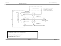
External power cable connections ....................................................................................................................5-4
5.1.4
Overall general arrangement.............................................................................................................................5-5
5.1.5
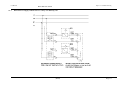
Connection of the external isolators utilizing users external power supply ....................................................5-6
5.1.6
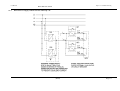
External Power Supply realization for 230VAC shunt trip coils....................................................................5-7
5.1.7
External Power Supply realization for low voltage AC shunt trip coils..........................................................5-8
5.1.8
External Power Supply realization for DC shunt trip coils..............................................................................5-9
5.1.9
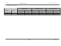
Circuit breaker selection chart ....................................................................................................................... 5-10
LIMITED WARRANTY ................................................................................................................................................ 5-11

User Manual
N
N
e
e
t
t
w
w
o
o
r
r
k
k
P
P
o
o
w
w
e
e
r
r
S
S
w
w
i
i
t
t
c
c
h
h
2
2
(08/10) Page ii
This manual describes the following equipment:
EQUIPMENT PART NUMBER
7,3kVA, 230V, 32A, 2 Pole Network Power Switch SSWITCH2-32A
Support Information:
If you require assistance for any reason, please have the following information available:
Model and size
Serial number
Date installed
Location
Voltage & Frequency

User Manual Chapter 1 - General Description
N
N
e
e
t
t
w
w
o
o
r
r
k
k
P
P
o
o
w
w
e
e
r
r
S
S
w
w
i
i
t
t
c
c
h
h
2
2
(08/10)
Page 1-1
1 Chapter 1 – General description
1.1 Introduction
The Network Power Switch (NPS) is an automatic static transfer switch designed to provide fast automatic transfers
between two independent, synchronous/asynchronous AC power sources to provide continuity of AC power to critical
equipment, such as information technology equipment.
One of the two AC inputs is designated as the “preferred” source to which the Network Power Switch will connect the
load as long as the designated input source is within the acceptable limits. The Network Power Switch is designed to
transfer the output load to the “alternate “input source, as long as the alternate source is within the acceptable voltage
limits and the preferred source is not.
The Network Power Switch provides fast, break-before-make transfers to prevent interconnection of the two sources,
even under faulted source conditions.
The maximum sense and transfer times are within the tolerance of IEEE Standard 446 susceptibility curve for
information technology equipment to allow uninterrupted load equipment operation.
In case of overload, Network Power Switch gives the alarm. Under Short-circuit condition a fast acting semi conductor
fuse protects condition of the load.
The Network Power Switch is 2 pole switch to prevent objectionable currents in the earth due to separate grounding
systems for the two sources.
Manual Bypass Switch
The entire power static switch module is hot swappable. Before removing this module the load is transferred, without
break to any one of the source directly by using the Manual bypass switch. After replacing the static switch module, the
load is restored on static switch module, using the Manual bypass switch.
Block Diagram
Fig 1.1 – Block Diagram of Network Power Switch

User Manual Chapter 1 - General Description
N
N
e
e
t
t
w
w
o
o
r
r
k
k
P
P
o
o
w
w
e
e
r
r
S
S
w
w
i
i
t
t
c
c
h
h
2
2
(08/10)
Page 1-1
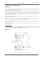
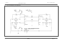
1.2 Design Concept
Fig 1.2 - Power Circuit Diagram for Network Power Switch
Figure 1.2 shows the Power circuit diagram for Network Power Switch. Source 1 & Source 2 are the two
synchronized/unsynchronized power sources with fuse switches FS1 & FS2 & pair of SCR’s TA1 & TB1 in series
with each path &TA2 and TB2 in the neutral path
Logic dictates that at any time only one pair of back-to-back connected SCR’s in the line and neutral should conduct.
This routes the input power to the output load. Should the load feeding source fail due to any reason; the other source
takes over automatically in less than 6 ms in case of synchronized sources and in less then 16 ms in case of
unsynchronized sources.
The change over is always with break, which ensures that in no case two sources get paralleled.
Priority source can be selected through front panel switch. The live mimic on front panel indicates which source is on
priority & which is feeding the load. Figure 1.4 shows the details of live mimic panel.

User Manual Chapter 1 - General Description
N
N
e
e
t
t
w
w
o
o
r
r
k
k
P
P
o
o
w
w
e
e
r
r
S
S
w
w
i
i
t
t
c
c
h
h
2
2
(08/10)
Page 1-2
1.3 Mechanical Design Description
Fig 1.3 – Hotswap and Fixed Unit
The Network Power Switch consists of two modules.
The fixed unit consists of the input and output connections and manual bypass transfer control switch.
The second module is hot swappable plug-in type with removable electronics & static switching module.
The Manual Bypass switch is located on the right side of the cabinet with a key lock to restrict access to qualified or
designated operators. The Hotswap contains locked latches to prevent unauthorized removal of the module. The
Network Power Switch is designed to allow replacement of the removable electronics /switching module without
having to de-energize the load equipment.
The Entire power static switch module is detachable. Before removing this module the load is transferred without break
to any one of the source directly. After replacing the static switch module, the load is again transferred back to Network
Power Switch without break. Refer to section 3.4 for safe removal and fixing of Hotswap unit on page 3-5.
Fixed unit
Telescopic Slides
Manual Bypass
Switch
Lock
Hotswap unit

User Manual Chapter 1 - General Description
N
N
e
e
t
t
w
w
o
o
r
r
k
k
P
P
o
o
w
w
e
e
r
r
S
S
w
w
i
i
t
t
c
c
h
h
2
2
(08/10)
Page 1-3
1.4 Mimic Indications
Fig 1.4 – Mimic and LED Indications
LED INDICATION
Mimic indications: Ten LED’s are mounted on the mimic plate;
Glowing LED’s indicate the status of the Network Power Switch.
S1 Healthy: Source –1 is a healthy source and is well above the 10% under voltage setting.
S2 Healthy: Source –2 is a healthy source and is well above the 10% under voltage setting.
S1 Priority: The priority selector switch is on S1 priority position.
S2 Priority: The priority selector switch is on S2 priority position.
S1 Feeding: The load is fed through source -1.
S2 Feeding: The load is fed through source -2.
Overload: Overload has occurred i.e. current level crossed 110% of full load.
Unsynchronized: The sources are out of phase-synchronized window.
Load on S1: Source –1 is feeding the load.
Load on S2: Source –2 is feeding the load.
S1 Healthy S1 Priority S1 Feeding
S2 Healthy S2 Priority S2 Feeding
Priority
Selection
Switch
Load on S1
Load on S2
Overload
Unsynchronised transfer

User Manual Chapter 1 - General Description
N
N
e
e
t
t
w
w
o
o
r
r
k
k
P
P
o
o
w
w
e
e
r
r
S
S
w
w
i
i
t
t
c
c
h
h
2
2
(08/10)
Page 1-4
1.5 Manual Bypass Switch Operation
Fig 1.5 – Manual Bypass Switch Operation
Manual Bypass switch is used only when a fault occurs in the Network Power Switch and the control circuitry of
the Network Power Switch is to be checked. To perform this operation the load is connected to the bypass. For
Normal Operation, the position of the switch should be at Network Power Switch output position (i.e. horizontal)
If the load is to be fed through the source 1 Bypass, first it is to be unlocked and the knob should be rotated
upwards. To feed through source 2 bypass the knob is to be rotated downward.
A mechanical interlocking arrangement is provided on this Bypass switch, by which the Hot swappable unit can be
removed only when load is connected to bypass. In normal operation when the load is connected to Network Power
Switch, the Hot swappable unit cannot be removed.
Operating Network Power Switch in Bypass mode
• Unlock the Manual Bypass Switch with the key provided.
• Depending upon the available healthy source (i.e. either Source-1 or Source-2 ) select it by changing the
Manual Bypass Switch position. Because of the make-before-break operations of the switch it is necessary
to select the bypass line on the source, which was feeding the output of the NPS previously, otherwise the
unsynchronized sources will be shorted resulting in fuse(s) blow.
• Unlock the sliding module
Load feed through source 1 BYPASS
Load feed through NPS OUTPUT
Load feed through source 2 BYPASS

User Manual Chapter 1 - General Description
N
N
e
e
t
t
w
w
o
o
r
r
k
k
P
P
o
o
w
w
e
e
r
r
S
S
w
w
i
i
t
t
c
c
h
h
2
2
(08/10)
Page 1-5
• Pull out the Hot swappable sliding module out of the Network Power Switch, which contains SCR
assembly and control circuitry.
Operating Network Power Switch in Normal Mode (load connected to Network Power Switch output)
• Insert the Hot swappable module into the Network Power Switch unit
• Lock the sliding module for preventing its accidental opening.
• Unlock the Manual Bypass Switch with the key provided
• Connect the Load output to Network Power Switch by changing the switch position to Network Power
Switch output.
• Depending on the priority switch, Load will get transferred to source-1, if the priority switch is on source1.
• The Static Switch output position LED will glow
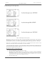
1.6 Potential free contacts
The Network Power Switch status can be checked on the connectors located on the rear end, as shown in figure 1.6.
Two potential free contacts indicating Source 1 and Source 2 Healthy conditions are taken from controller board and
terminated at rear terminal connectors, as shown in figure 1.6. These two voltage free contacts are Normally Open
(NO) and their rating is 1A / 2A @ 120Vac / 24Vdc.
Fig 1.6 – Potential free contacts Connectors
Way of using the Potential Free Contacts (PFC)
Source Healthy Signals
a) Independent b) Parallel c) Series
The potential free contacts can be used in the above drawn way
52
50
51
52
50
51
52
50
51

User Manual Chapter 1 - General Description
N
N
e
e
t
t
w
w
o
o
r
r
k
k
P
P
o
o
w
w
e
e
r
r
S
S
w
w
i
i
t
t
c
c
h
h
2
2
(08/10)
Page 2-1
Optional:
1NO + 1NC Auxiliary contact block stackable to siemens circuit breaker
Auxilliary Backfeed indication contact:
13
21
22
14
Note : a) The line shows PFC inside NPS
b) The numbers indicated in the boxes are wire numbers coming to PFC terminals
2 Chapter 2 – Operating Instructions
2.1 Introduction
The Network Power Switch can be considered to be in one of the three operating conditions:
• Normal Operation - All relevant power switches and fuses closed and the Load is connected to Network
Power Switch output
• Manual Bypass – The load is connected to the input supply directly.
• Shut down - All power switches are off and load is not operational.
• Blown Fuse – One or both of the input fuses are blown. Before replacing with the fuse(s) of the prescribed
type it is recommended to check if there is no short circuit present on the output. If the failure condition is
repeated even after verifying there is no short circuit present at the output it is necessary to contact the service.
• Backfeed failure : Faulty condition when the unit isolated the source connected to faulty internal switch – to
resolve the error it is necessary to contact the service. The controlled isolation of the source due this reason is
indicated also via the status of BF dry contacts (Optional for CB).
2.2 General Notes
NOTE: All users controls and indicators mentioned in these procedures are identified in chapter1
Fig 2.1 - Power Connection details for Network Power Switch

User Manual Chapter 1 - General Description
N
N
e
e
t
t
w
w
o
o
r
r
k
k
P
P
o
o
w
w
e
e
r
r
S
S
w
w
i
i
t
t
c
c
h
h
2
2
(08/10)
Page 2-2
2.3 Procedure for Switching the Network Power Switch to power the load from a Power Off
condition
This procedure should be followed when turning on the Network Power Switch from a fully powered down condition
-i.e. When the load is not being initially supplied at all. It is assumed that the installation is complete; the authorized
personnel have commissioned the system.
1. Select the priority to source1. Close the fuse FS1.
2. Check for the LED S1 healthy, S1 priority, S1 feed and LED load on source1 to glow.
3. Close the fuse FS2.
4. Check for the LED S2 healthy to glow.
5. Using priority switch transfer the load to source2, check this transfer does not affect the load.
6. Transfer the load to source 1 again and check this transfer does not affect the load.
2.4 Switching the Load to Manual Bypass condition
Fig 2.2 – Switching to Bypass
WARNING
This operation should be performed by Trained personnel only.
SWITCH TO YELLOW LED ‘ON’ POSITION ONLY.
1. By seeing the LED indication check which source is feeding.
2. Unlock the Bypass switch lock by the using the key provided.
3. Rotate the Manual Bypass switch in the direction of the source feeding the load as per the warning given on the
mimic.
4. Relock the Bypass switch, remove the key and keep it in original place.
Yellow LED (Load on S1)
Yellow LED (Load on S2)
‘ON’
Bypass on S2 SOURCE
Load connected to this bypass
Bypass on S1 SOURCE

User Manual Chapter 1 - General Description
N
N
e
e
t
t
w
w
o
o
r
r
k
k
P
P
o
o
w
w
e
e
r
r
S
S
w
w
i
i
t
t
c
c
h
h
2
2
(08/10)
Page 3-3
2.5 Procedure for switching the Network Power Switch from Manual Bypass condition to
Normal Operation
1. Unlock the Bypass switch using the key provided.
2. Rotate the bypass switch knob to the Static switch output position, i.e. horizontal position.
3. Lock the Bypass Switch, remove the key and keep it in original place.
3 Chapter 3 – Installation Procedure
3.1 Introduction
WARNING
Do not apply electrical power to the Network Power Switch equipment before the arrival of the
commissioning engineer.
See installation instructions before connecting to the supply.
WARNING
The Network Power Switch equipment should be installed by a qualified engineer in accordance with the
information contained in this chapter and the drawing package shipped inside UPS cabinet.
This chapter contains information regarding the positioning and cabling of the Network Power Switch.
Because every site has its peculiarities, it is not the aim of this chapter to provide step-by-step installation
instructions, but to act as a guide to the general procedures and practices that should be observed by the
installing engineer
.
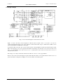
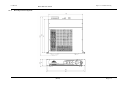
3.2 Equipment positioning and environmental considerations
The Network Power Switch cabinets are designed to fit in standard 19-inch rack. In case of non-availability, it can be
kept on floor or as a tabletop item, with sufficient ground clearance.
Network Power Switch should be located in a cool, dry, clean environment with adequate ventilation to keep the
ambient temperature within the specified operating range.
WARNING
The Network Power Switch cabinet is connected with live voltages,
hence it should be located at safe place.
To ensure efficient cooling 1U free space above the unit is necessary
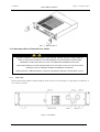
For installing the NPS in standard 19” Rack, remove the Nuts used for ‘Safety Clamps’ as shown in the figure 3.1.
After keeping the NPS cabinet inside the rack, fix the cabinet with Safety Clamps intact, using same screws.

User Manual Chapter 1 - General Description
N
N
e
e
t
t
w
w
o
o
r
r
k
k
P
P
o
o
w
w
e
e
r
r
S
S
w
w
i
i
t
t
c
c
h
h
2
2
(08/10)
Page 3-4
3.3 Connecting cables to Network Power Switch
WARNING
BEFORE CABLING-UP THE NETWORK POWER SWITCH, ENSURE THAT YOU ARE AWARE OF
THE LOCATION AND OPERATION OF THE EXTERNAL ISOLATORS THAT CONNECT THE
NETWORK POWER SWITCH INPUT SUPPLY TO THE MAINS DISTRIBUTION PANEL.
CHECK THAT THESE SUPPLIES ARE ELECTRICALLY ISOLATED, AND POST ANY NECESSARY
WARNING SIGNS TO PREVENT THEIR INADVERTENT OPERATION.
HIGH LEAKAGE CURRENT EARTH CONNECTION ESSENTIAL BEFORE CONNECTING SUPPLY.
3.3.1 Cable entry
Cables enter the Network Power Switch cabinet from the rear side as shown in figure 3.2. The cables are terminated on
the connectors and fuses.
Fig 3
.1
–
NPS Installation
Fig 3.2
–
Cable Entry

User Manual Chapter 1 - General Description
N
N
e
e
t
t
w
w
o
o
r
r
k
k
P
P
o
o
w
w
e
e
r
r
S
S
w
w
i
i
t
t
c
c
h
h
2
2
(08/10)
Page 3-1
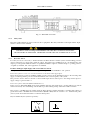
3.3.2 Cable Rating
Following are the recommended cable size for 7,3kVA Network Power Switch –
Table 3-1
Description Max. Current rating (Amp) PVC cable (mm
2
)* Max Cable (mm
2)
Input Cables 32 3G6 3G10
Output Cables 32 3G6 3G10
Signalization&coil drive 2 10 x 0,25 ** -
* Recommended cable size for Input & Output terminals (CTS10U) is 1.5 to 10 mm
2
.
** Higher dimension limited by cable gland capability
Note:
• It is recommended to use cables with suitable lugs to avoid any short circuit between terminals.
• These recommendations are for guideline purposes only and may be superseded by local regulations and
codes of practices.
Fig. 3.3 – External cable routing
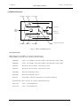
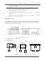
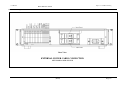
3.3.3 Cable connections
Following are the set of external power cables, which are connected to the Network Power Switch equipment –
• Input source 1 – Line 1
• Input source 2 – Line 2
• Input source 1 – Neutral 1
• Input source 2 – Neutral 2
• Output – Line
• Output – Neutral
• Earthing ( PE )
• External shunt trip coil drive contacts
• Source state signalization (Source Healthy)
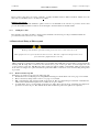
These cables are connected to the terminals on rear side of the equipment as shown in fig 3.4

User Manual Chapter 1 - General Description
N
N
e
e
t
t
w
w
o
o
r
r
k
k
P
P
o
o
w
w
e
e
r
r
S
S
w
w
i
i
t
t
c
c
h
h
2
2
(08/10)
Page 3-2
Fig 3.4 – External Power Cables
3.3.4 Safety earth
The safety earth terminal is provided on the rear side of equipment .The safety earth cable of the inputs and the output
must be connected to this terminal.
WARNING
FAILURE TO FOLLOW ADEQUATE EARTHING PROCEDURES CAN RESULT IN ELECTRIC
SHOCK HAZARD TO PERSONNEL, OR THE RISK OF FIRE, SHOULD AN EARTH FAULT OCCUR.
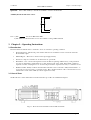
3.3.5 Protective devices
For safety reasons, it is necessary to install external to the Network Power Switch system, circuit breaking protective
devices in the input a.c. supply and towards the output. Given that every installation has its own characteristics, this
chapter provides general useful information for qualified installation engineers, with knowledge of operating practices,
of regulatory standards, and of the equipment to be installed.
Rectifier and Bypass input supply of the Network Power Switch:
The input to Network Power Switch should be given through a 32A, 2 Pole ELCB for safe operation.
Protection against excessive over currents and short-circuits in the mains supply input:
These inputs must be protected, installing suitable protective devices at the distribution panel of the incoming main
supply, considering that the protection should discriminate with overload capacity of the system.
The protective devices must be selected for the nominal input current, with respect to the rating and the input a.c.
supply voltage as given in table 3-1
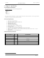
Protection against earth faults (RCD or RCCB devices):
In the event of a differential (RCD) device being installed upstream of the input supply, one must take into account the
transient and steady state earth leakage currents that are produced during start-up of the Network Power Switch.
The presence of an RFI suppression filter inside the Network Power Switch determines a residual earth current not
greater than 3.5mA. Residual current circuit breakers (RCCB / RCD) must be sensitive to d.c. unidirectional pulses
(class A) in the network and insensitive to transient current pulses.
Thy are identified by the symbols respectively:

User Manual Chapter 1 - General Description
N
N
e
e
t
t
w
w
o
o
r
r
k
k
P
P
o
o
w
w
e
e
r
r
S
S
w
w
i
i
t
t
c
c
h
h
2
2
(08/10)
Page 3-3
These isolators must have an average sensitivity, possibly adjustable between 10mA and 0.3A; further more the
intervention of the RCD’s have to be delayed of > 90 ms.
Output to the System:
In the event that an external distribution panel is used for load distribution, the selection of protective device must
provide discrimination with those that are used at the input to the Network Power Switch module.
3.3.6 Cabling Procedure
The external power cables should be connected to the terminals as shown in fig 3.2. Proper termination labels are
provided near each connector for ease of cabling.
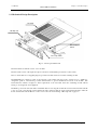
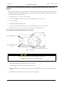
3.4 Removal and Fixing of Hotswap unit
WARNING
Hotswap unit should be opened by trained person only as it is connected to live load.
This equipment receives power from more than one source. Disconnect output and all input sourcesn of
power from this equipment before servicing.
NPS is designed for quick and easy maintenance / serviceability. The SCRs and control circuitry is located inside the
Hotswap unit. Hotswap unit is connected to the main body by a pair of telescopic slides on left and right side, and
power connector at rear end. This Hotswap unit is easily removable by pulling out the handle, which is located in the
front. Since it is dangerous to pull out the Hotswap unit when NPS is connected to load, an interlocking arrangement
is provided.
3.4.1 Removal of Hotswap unit
Following is procedure for safe removal of Hotswap unit:
1. Transfer the load to healthy Bypass by using Maintenance Bypass switch. Refer section 2.4, page 2-2 for details.
2. Remove the Safety clamps. Refer section 3.2 on page 3-1 for details.
3. Pull out the Hotswap unit using the handle located in front. The movement will get restricted at certain distance,
which ensures that the Hotswap unit does not fall down in open condition.
4. A small plastic lever is located inside both telescopic slides. Press the left lever downwards and right lever
upwards, as shown in fig 3-3. This will unlock the slide and Hotswap unit can be pulled out completely.
Page is loading ...
Page is loading ...
Page is loading ...
Page is loading ...
Page is loading ...
Page is loading ...
Page is loading ...
Page is loading ...
Page is loading ...
Page is loading ...
Page is loading ...
Page is loading ...
Page is loading ...
Page is loading ...
Page is loading ...
Page is loading ...
-
 1
1
-
 2
2
-
 3
3
-
 4
4
-
 5
5
-
 6
6
-
 7
7
-
 8
8
-
 9
9
-
 10
10
-
 11
11
-
 12
12
-
 13
13
-
 14
14
-
 15
15
-
 16
16
-
 17
17
-
 18
18
-
 19
19
-
 20
20
-
 21
21
-
 22
22
-
 23
23
-
 24
24
-
 25
25
-
 26
26
-
 27
27
-
 28
28
-
 29
29
-
 30
30
-
 31
31
-
 32
32
-
 33
33
-
 34
34
-
 35
35
-
 36
36


Liebert SSWITCH2-32A Installation guide
- Category
- Power distribution units (PDUs)
- Type
- Installation guide
- This manual is also suitable for
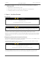
Ask a question and I''ll find the answer in the document
Finding information in a document is now easier with AI
Related papers
-
Liebert 110V User manual
-
Liebert Series 610 User manual
-
-
-
-
-
-
Emerson NXE0A0015F User manual
-
-
Other documents
-
-
-
-
Emerson GXT3 Warranties
-
-
-
-
-
Emerson GXT4-144VBATT Datasheet
-