
Operating instructions
K3G250-PR17-I5
Translation of the original operating instructions
ebm-papst Mulfingen GmbH & Co. KG
Bachmühle 2
D-74673 Mulfingen
Phone +49 (0) 7938 81-0
Fax +49 (0) 7938 81-110
www.ebmpapst.com
CONTENTS
1. SAFETY REGULATIONS AND NOTES
11. SAFETY REGULATIONS AND NOTES
Please read these operating instructions carefully before starting to work
with the device. Observe the following warnings to prevent malfunctions
or physical damage to both property and people.
These operating instructions are to be regarded as part of this device.
If the device is sold or transferred, the operating instructions must
accompany it.
These operating instructions may be duplicated and forwarded for
information about potential dangers and their prevention.
1.1 Levels of hazard warnings
11.1 Levels of hazard warnings
These operating instructions use the following hazard levels to indicate
potentially hazardous situations and important safety regulations:
DANGER
Indicates an imminently hazardous situation which, if not
avoided, will result in death or serious injury. Compliance with
the measures is mandatory.
WARNING
Indicates a potentially hazardous situation which, if not avoided,
could result in death or serious injury. Exercise extreme
caution while working.
CAUTION
Indicates a potentially hazardous situation which, if not avoided,
may result in minor or moderate injury or damage of property.
NOTE
A potentially harmful situation can occur and, if not avoided, can
lead to property damage.
1.2 Staff qualification
11.2 Staff qualification
The device may only be transported, unpacked, installed, operated,
maintained and otherwise used by qualified, trained and authorised
technical staff.
Only authorised specialists are permitted to install the device, to carry
out a test run and to perform work on the electrical installation.
1.3 Basic safety rules
11.3 Basic safety rules
Any safety hazards stemming from the device must be re-evaluated
once it is installed in the end device.
The local industrial safety regulations must always be observed when
working on the device.
Keep the workplace clean and tidy. Untidiness in the working area
increases the risk of injury.
Observe the following when working on the unit:
; Do not make any modifications, additions or conversions to the
device without the approval of ebm-papst.
1.4 Electrical voltage
11.4 Electrical voltage
; Check the electrical equipment of the device at regular intervals, refer
to chapter 6.3 Safety test.
; Replace loose connections and defective cables immediately.
DANGER
Electrical load on the device
Risk of electric shock
→ Stand on a rubber mat if you are working on an electrically
charged device.
21.5 Safety and protective functions
21.6 Electromagnetic radiation
21.7 Mechanical movement
21.8 Emission
21.9 Hot surface
21.10 Transport
21.11 Storage
32. PROPER USE
43. TECHNICAL DATA
43.1 Product drawing
53.2 Nominal data
53.3 Data in accordance with ecodesign regulation EU 327/2011
53.4 Technical features
63.5 Mounting data
63.6 Transport and storage conditions
64. CONNECTION AND START-UP
64.1 Connecting the mechanical system
64.2 Connecting the electrical system
74.3 Connection in terminal box
84.4 Factory settings
94.5 Connection screen
104.6 Checking the connections
104.7 Switch on device
104.8 Switching off the device
105. INTEGRATED PROTECTIVE FUNCTIONS
106. MAINTENANCE, MALFUNCTIONS, POSSIBLE
CAUSES AND REMEDIES
116.1 Vibration test
116.2 Cleaning
116.3 Safety test
126.4 Disposal
Item no. 54783-5-9970 · ENG · Revision 202174 · Release 2018-12-28 · Page 1 / 12
ebm-papst Mulfingen GmbH & Co. KG · Bachmühle 2 · D-74673 Mulfingen · Phone +49 (0) 7938 81-0 · Fax +49 (0) 7938 81-110 · [email protected] · www.ebmpapst.com

Operating instructions
K3G250-PR17-I5
Translation of the original operating instructions
WARNING
Terminals and connections have voltage even with a
unit that is shut off
Electric shock
→ Wait five minutes after disconnecting the voltage at all poles
before opening the device.
CAUTION
In the event of failure, there is electric voltage at the
rotor and impeller
The rotor and impeller are base insulated.
→ Do not touch the rotor and impeller once they are installed.
CAUTION
If control voltage is applied or a speed setpoint is stored,
the motor will restart automatically, e.g. after a mains
failure.
Risk of injury
→ Keep out of the device hazard zone.
→ When working on the device, switch off the mains power
and ensure that it cannot be switched back on.
→ Wait until the device stops.
→ After working on the device, remove any tools used or
other objects from the device.
1.5 Safety and protective functions
DANGER
Protective device missing and protective device not
functioning
Without a protective device there is a risk of serious injury, for
instance when reaching into the device during operation.
→ Operate the device only with a fixed protective device and
guard grille.
→ The fixed protective device must be able to withstand the
kinetic energy of a fan blade that becomes detached at
maximum speed. There must not be any gaps which it is
possible to reach into with the fingers, for example.
→ The device is a built-in component. As the operator, you
are responsible for ensuring that the device is secured
adequately.
→ Stop the device immediately if a protective device is
found to be missing or ineffective.
1.6 Electromagnetic radiation
Interference from electromagnetic radiation is possible, e.g. in conjunction
with open and closed-loop control devices.
If unacceptable emission intensities occur when the fan is installed,
appropriate shielding measures have to be taken by the user.
NOTE
Electrical or electromagnetic interferences after
integrating the device in installations on the customer's
side.
→ Verify that the entire setup is EMC compliant.
1.7 Mechanical movement
DANGER
Rotating device
Body parts that come into contact with the rotor and impeller
can be injured.
→ Secure the device against accidental contact.
→ Before working on the system/machine, wait until all
parts have come to a standstill.
WARNING
Rotating device
Long hair, dangling items of clothing, jewellery and similar items
can become entangled and be pulled into the device. Risk of
injury.
→ Do not wear any loose-fitting or dangling clothing or jewellery
while working on rotating parts.
→ Protect long hair with a cap.
1.8 Emission
WARNING
Depending on the installation and operating conditions,
a sound pressure level greater than 70 dB(A) may arise.
Danger of noise-induced hearing loss
→ Take appropriate technical safety measures.
→ Protect operating personnel with appropriate safety
equipment, e.g. hearing protection.
→ Also observe the requirements of local agencies.
1.9 Hot surface
CAUTION
High temperature at the electronics housing
Risk of burns
→ Ensure sufficient contact protection.
1.10 Transport
NOTE
Transporting the device
→ Transport the device in its original packaging only.
1.11 Storage
; Store the device, partially or fully assembled, in the original
packaging in a clean, dry and weatherproof place free of vibrations.
; Protect the device against environmental effects and dirt until final
installation.
; We recommend storing the device for no longer than one year in
order to guarantee trouble-free operation and longest possible service
life.
; Even devices explicitly intended for outdoor use are to be stored as
described prior to commissioning.
; Maintain the storage temperature, see
chapter 3.6 Transport and storage conditions.
; Please make sure that all screwed cable glands are fitted with
dummy plugs.
Item no. 54783-5-9970 · ENG · Revision 202174 · Release 2018-12-28 · Page 2 / 12
ebm-papst Mulfingen GmbH & Co. KG · Bachmühle 2 · D-74673 Mulfingen · Phone +49 (0) 7938 81-0 · Fax +49 (0) 7938 81-110 · [email protected] · www.ebmpapst.com

Operating instructions
K3G250-PR17-I5
Translation of the original operating instructions
2. PROPER USE
The device is exclusively designed as a built-in device for conveying
air according to its technical data.
Any other usage above and beyond this does not conform with the
intended purpose and constitutes misuse of the device.
Customer equipment must be capable of withstanding the mechanical
and thermal stresses that can arise from this product. This applies for the
entire service life of the equipment in which this product is installed.
Proper use also includes:
● The device is only to be used in systems with earthed neutral (TN/TT
systems), in phase-to-earth systems or in IT systems.
● Use of the device in stationary systems only.
● Conveying of air at an ambient air pressure of 800 mbar to 1050 mbar.
● Using the device in accordance with the permitted ambient
temperature, see chapter 3.6 Transport and storage conditions and
chapter 3.2 Nominal data.
● Operating the device with all protective features in place.
● Minding the operating instructions.
Improper use
Using the device in the following ways is particularly prohibited and
may cause hazards:
● Operating the device with an imbalance, e.g. caused by dirt deposits
or icing.
● Resonance mode, operation with heavy vibrations. These also
include vibrations that are transmitted from the customer system to the
fan.
● Operation in medical equipment with a life-sustaining or lifesaving
function.
● Moving solids content in flow medium.
● Painting the device
● Connections (e.g. screws) coming loose during operation.
● Opening the terminal box during operation.
● Moving air that contains abrasive particles.
● Moving highly corrosive air, e.g. salt spray mist. Exceptions are
devices that are intended for salt spray mist and protected accordingly.
● Moving air that contains dust pollution, e.g. suctioning off saw dust.
● Operating the device close to flammable materials or components.
● Operating the device in an explosive atmosphere.
● Using the device as a safety component or for taking on safety-
related functions.
● Operation with completely or partially disassembled or modified
protective features.
● In addition, all application options that are not listed under proper use.
Item no. 54783-5-9970 · ENG · Revision 202174 · Release 2018-12-28 · Page 3 / 12
ebm-papst Mulfingen GmbH & Co. KG · Bachmühle 2 · D-74673 Mulfingen · Phone +49 (0) 7938 81-0 · Fax +49 (0) 7938 81-110 · [email protected] · www.ebmpapst.com

Operating instructions
K3G250-PR17-I5
Translation of the original operating instructions
3. TECHNICAL DATA
3.1 Product drawing
All measures have the unit mm.
1 Cable diameter min. 8 mm, max. 12 mm, tightening torque 1.8±0.3 Nm (use the provided seal)
Cable diameter min. 4 mm, max. 10 mm, tightening torque 1.8±0.3 Nm
2 Cable diameter min. 6 mm, max. 10 mm, tightening torque 1.8±0.3 Nm (use the provided seal)
Cable diameter min. 4 mm, max. 7 mm, tightening torque 1.8±0.3 Nm
3 Tightening torque 1.5±0.2 Nm
4 Inlet nozzle with pressure tap (k-factor: 76)
5 Mounting for inlet nozzle and FlowGrid
Item no. 54783-5-9970 · ENG · Revision 202174 · Release 2018-12-28 · Page 4 / 12
ebm-papst Mulfingen GmbH & Co. KG · Bachmühle 2 · D-74673 Mulfingen · Phone +49 (0) 7938 81-0 · Fax +49 (0) 7938 81-110 · [email protected] · www.ebmpapst.com

Operating instructions
K3G250-PR17-I5
Translation of the original operating instructions
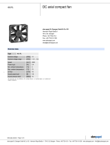
3.2 Nominal data
Motor M3G084-DF
Phase 1~
Nominal voltage / VAC 230
Nominal voltage
range / VAC
200 .. 277
Frequency / Hz 50/60
Type of data definition ml
Speed (rpm) / min
-1
3450
Power input / W 750
Current draw / A 3.3
Min. ambient
temperature / °C
-40
Max. ambient
temperature / °C
45
ml = Max. load · me = Max. efficiency · fa = Running at free air
cs = Customer specs · cu = Customer unit
Subject to alterations
3.3 Data in accordance with ecodesign regulation EU 327/
2011
Actual Request 2015
01 Overall efficiency ηes / % 67 49.9
02 Measurement category A
03 Efficiency category Static
04 Efficiency grade N 79.1 62
05 Variable speed drive Yes
06 Year of manufacture
The year of manufacture is specified on the
rating plate on the product.
07 Manufacturer
ebm-papst Mulfingen GmbH & Co. KG
County court Stuttgart · HRA 590344
D-74673 Mulfingen
08 Type K3G250-PR17-I5
09 Power input Ped / kW 0.71
09 Air flow qv / m³/h 2110
09 Pressure increase total psf /
Pa
749
10 Speed (rpm) n / min
-1
3395
11 Specific ratio
*
1.01
12 Recycling/disposal
Information on recycling and disposal is
provided in the operating instructions.
13 Maintenance
Information on installation, operation and
maintenance is provided in the operating
instructions.
14 Additional components
Components used to calculate the energy
efficiency that are not apparent from the
measurement category are detailed in the
CE declaration.
*
Specific ratio = 1 + pfs / 100 000 Pa
Data definition with optimum efficiency. The ErP data is determined using a motor-impeller
combination in a standardised measurement configuration.
3.4 Technical features
Mass 9.2 kg
Size 250 mm
Motor size 84
Surface of rotor Coated in black
Material of terminal box PP plastic
Material of electronics
housing
Die-cast aluminium
Material of impeller PP plastic
Material of mounting
plate
Sheet steel, galvanised
Material of support
bracket
Steel, coated in black
Material of inlet nozzle Sheet steel, galvanised
Number of blades 6
Direction of rotation Clockwise, seen on rotor
Type of protection IP55
Insulation class "F"
Humidity (F) /
environmental
protection class (H)
H1
Note ambient
temperature
Occasional start-up between -40 °C and -
25 °C is permissible. For continuous
operation at ambient temperatures below -
25 °C (e.g. refrigeration applications), a
fan version with special low-temperature
bearings must be used.
Mounting position Shaft horizontal or rotor on bottom; rotor
on top on request
Condensation
drainage holes
Rotor-side
Operation mode S1
Motor bearing Ball bearing
Technical features - Output 10 VDC, max. 10 mA
- Operation and alarm display
- Alarm relay
- Integrated PID controller
- Output limit
- Motor current limit
- PFC, active
- RS485 MODBUS RTU
- Soft start
- Control input 0-10 VDC / PWM
- Control interface with SELV potential
safely disconnected from the mains
- Over-temperature protected
electronics / motor
- Line undervoltage / phase failure
detection
Touch current acc.
IEC 60990 (measuring
network Fig. 4, TN
system)
<= 3.5 mA
Electrical connection Terminal box
Motor protection Thermal overload protector (TOP) wired
internally
Cable exit Variable
Protection class I (if protective earth is connected by
customer)
Item no. 54783-5-9970 · ENG · Revision 202174 · Release 2018-12-28 · Page 5 / 12
ebm-papst Mulfingen GmbH & Co. KG · Bachmühle 2 · D-74673 Mulfingen · Phone +49 (0) 7938 81-0 · Fax +49 (0) 7938 81-110 · [email protected] · www.ebmpapst.com

Operating instructions
K3G250-PR17-I5
Translation of the original operating instructions
Product conforming
to standard
EN 61800-5-1; CE
Approval UL 1004-7 + 60730-1; CCC; CSA
C22.2 no. 77 + CAN/CSA-E60730-1
For cyclic speed loads, note that the rotating parts of the device
are designed for maximum one million load cycles. If you have
specific questions, contact ebm-papst for support.
; Use the device in accordance with its protection type.
Notes on surface quality
The surfaces of the products conform to the generally applicable industrial
standard. The surface quality may vary during the production period.
Strength, dimensional stability and dimensional accuracy are not affected
by this.
The colour pigments of the paints used react perceptibly to UV light over
the course of time. This does not however have any influence on the
technical properties of the products. To prevent the formation of patches
and fading, the product is to be protected against UV radiation. Changes
in colour are not a reason for complaint and are not covered by the
warranty.
3.5 Mounting data
; Secure the mounting screws against accidentally coming loose (e.g.
by using self-locking screws).
Strength class for
mounting screws
8.8
Any further mounting data required can be taken from the product
drawing or Section chapter 4.1 Connecting the mechanical system.
3.6 Transport and storage conditions
Max. permissible
ambient motor temp.
(transp./ storage)
+80 °C
Min. permissible
ambient motor temp.
(transp./storage)
-40 °C
4. CONNECTION AND START-UP
4.1 Connecting the mechanical system
CAUTION
Cutting and crushing hazard when removing device
from packaging
→ Carefully remove the device from its packaging, only
touching the housing. Strictly avoid shocks.
→ Wear safety shoes and cut-resistant safety gloves.
NOTE
Damage to device from vibration
Bearing damage, reduced service life
→ Forces or impermissibly high vibration levels must not be
transmitted to the fan from system components.
→ If the fan is connected to air ducts, it should isolated from
vibrations, for example using compensators or similar
elements.
→ Fasten the fan to the substructure without distorting it.
; The fan may not be handled in the area around the inlet nozzle during
transport and installation.
There is a risk of damage to the impeller.
; Check the device for transport damage. Damaged devices must no
longer be installed.
; Install the undamaged device according to your application.
CAUTION
Possibility of damage to the device
Serious damage may result if the device slips during assembly.
→ Keep the device fixed in position at the installation location
until all attachment screws have been tightened.
● The fan must not be strained on fastening.
4.2 Connecting the electrical system
DANGER
Electric voltage on the device
Electric shock
→ Always install a protective earth first.
→ Check the protective earth.
DANGER
Incorrect insulation
Risk of fatal injury from electric shock
→ Use only cables that meet the specified installation
requirements for voltage, current, insulation material, load etc.
→ Route cables such that they cannot be touched by any
rotating parts.
DANGER
Electrical load (>50 µC) between mains wire and
protective earth connection after switching of the supply
when switching multiple devices in parallel.
Electric shock, risk of injury
→ Make sure that sufficient protection against accidental contact
is provided.
Before working on the electrical connection, the
connections to the mains supply and PE must be shorted.
Item no. 54783-5-9970 · ENG · Revision 202174 · Release 2018-12-28 · Page 6 / 12
ebm-papst Mulfingen GmbH & Co. KG · Bachmühle 2 · D-74673 Mulfingen · Phone +49 (0) 7938 81-0 · Fax +49 (0) 7938 81-110 · [email protected] · www.ebmpapst.com

Operating instructions
K3G250-PR17-I5
Translation of the original operating instructions
CAUTION
Electrical voltage
The fan is a built-in component and features no electrically
isolating switch.
→ Only connect the fan to circuits that can be switched off with
an all-pole separating switch.
→ When working on the fan, you must switch off the
installation/machine in which the fan is installed and secure it
from being switched on again.
NOTE
Water penetration into leads or wires
Water enters at the cable end on the customers side and can
damage the device.
→ Make sure that the cable end is connected in a dry
environment.
Connect the device only to circuits that can be switched off
using an all-pole disconnecting switch.
4.2.1 Prerequisites
; Check that the data on the type plate match the connection data.
; Before connecting the device, ensure that the supply voltage matches
the operating voltage of the device.
; Only use cables designed for current according to the type plate.
For determining the cross-section, follow the basic principles in
accordance with EN 61800-5-1. The protective earth must have a
cross-section equal to or greater than the outer conductor cross-
section.
We recommend the use of 105°C cables. Ensure that the minimum
cable cross-section is at least
AWG26/0.13 mm².
; Note the following when routing the connection lines:
For permanently installed lines, the bending radius must be at least
four times the outside diameter of the cable.
For movable lines, the bending radius must be at least 15 times the
outside diameter of the cable.
Protective earth contact resistance as per EN 61800-5-1
Compliance with the resistance specifications as per EN 61800-5-1 for
the protective earth connection circuit must be verified in the application.
Depending on the installation situation, it may be necessary to connect
an additional protective earth conductor by way of the extra protective
earth terminal provided on the device. The protective earth terminal is
located on the housing and provided with a protective earth symbol and
a hole.
4.2.2 Idle current
Because of the EMC filter integrated for compliance with EMC
limits (interference emission and interference immunity), idle
currents in the mains cable can be measured even when the
motor is at a standstill and the mains voltage is switched on.
● The values are typically in the range < 250 mA
● At the same time, the effective power in this operating state
(operational readiness) is typically < 4 W.
4.2.3 Residual current operated device
If the use of a residual current device (RCD) is required in your
installation, only universal residual current devices (type B or
B+) are permissible. Residual current devices (RCD) cannot
provide personal safety while operating the device, as is also
the case with frequency converters. When the device power
supply is switched on, charging current pulses from the
capacitors in the integrated EMC filter can lead to the instant
triggering of residual current devices. We recommend residual
current circuit breakers (RCCB) with an activation threshold of
300 mA and delayed tripping (super-resistant, characteristic K).
4.2.4 Locked-rotor protection
Due to the locked-rotor protection, the start-up current (LRA) is
equal to or less than the nominal current (FLA).
4.3 Connection in terminal box
4.3.1 Preparing connection lines for the connection
Fig. 1: Recommended stripping lengths in mm (inside terminal box)
Strip the cable just enough so that the screwed cable gland is tight and
the terminals are relieved of strain. Tightening torque, see chapter 3.1
Product drawing.
NOTE
Tightness and strain relief depend on the cable used.
→ The user must check this.
4.3.2 Connecting cables with terminals
WARNING
Terminals and connections have voltage even with a
unit that is shut off
Electric shock
→ Wait five minutes after disconnecting the voltage at all poles
before opening the device.
; Remove the cap from the screwed cable gland.
Remove the cap only in those places where cables are inserted.
; Insert the line(s) (not included in the standard scope of delivery) into
the terminal box.
; First connect the "PE" (protective earth) connection.
; Connect the lines to the corresponding terminals.
Use a screwdriver to do so.
During the connection work, ensure that no cables splice off.
; Seal the terminal box.
Item no. 54783-5-9970 · ENG · Revision 202174 · Release 2018-12-28 · Page 7 / 12
ebm-papst Mulfingen GmbH & Co. KG · Bachmühle 2 · D-74673 Mulfingen · Phone +49 (0) 7938 81-0 · Fax +49 (0) 7938 81-110 · [email protected] · www.ebmpapst.com

Operating instructions
K3G250-PR17-I5
Translation of the original operating instructions
4.3.3 Cable routing
No water may penetrate along the cable in the direction of the cable gland.
NOTE
Damage caused by moisture penetration.
Moisture can penetrate into the terminal box if water is
constantly present at the cable glands.
→ To prevent the constant accumulation of water at the cable
glands, the cable should be routed in a U-shaped loop
(siphon) wherever possible.
→ If this is not possible, a drip edge can be produced by
fitting a cable tie directly in front of the cable gland for example.
Fig. 2: Fan installed lying flat, cable routed in a U-shaped loop.
When routing the cable, ensure that the screwed cable glands are
arranged at the bottom. The cables must always be routed downwards.
Fig. 3: Cable routing for fans installed upright.
4.4 Factory settings
Factory settings with which the device is pre-set by ebm-papst.
Control mode
parameter set 1
PWM controlling
Control mode
parameter set 2
PWM controlling
Fan / device adress 1
Max. PWM / % 100
Min. PWM / % 10
Save set value to
EEPROM
No
Set value control Analogue (linear)
Control function
parameter set 1
Positive (heating)
Control function
parameter set 2
Positive (heating)
Item no. 54783-5-9970 · ENG · Revision 202174 · Release 2018-12-28 · Page 8 / 12
ebm-papst Mulfingen GmbH & Co. KG · Bachmühle 2 · D-74673 Mulfingen · Phone +49 (0) 7938 81-0 · Fax +49 (0) 7938 81-110 · [email protected] · www.ebmpapst.com

Operating instructions
K3G250-PR17-I5
Translation of the original operating instructions
4.5 Connection screen
No. Conn. Designation Function / assignment
1 PE Protective earth
2 PE Protective earth
3 N Power supply, neutral conductor
4 - not used
5 L Power supply, phase
6 NC Status relay, floating status contact, break for failure, contact rating 250 VAC / 2 A (AC1) min. 10 mA, basic
insulation on mains side and reinforced insulation on control interface side
7 COM Status relay, floating status contact, common connection, contact rating 250 VAC / 2 A (AC1) / min. 10 mA,
basic insulation on mains side and reinforced insulation on control interface side
8 GND Signal ground for control interface, SELV
9 RSA RS-485 interface for MODBUS, RSA; SELV
10 RSB RS-485 interface for MODBUS, RSB; SELV
11 0-10 V Analogue input (set value) SELV, 0-10 V, Ri=100kΩ, parametrisable curve
12 +10 V Fixed voltage output 10 VDC, SELV, +10 V ±3%, max. 10 mA, short-circuit-proof, power supply for external
devices (e.g. potentiometer)
Item no. 54783-5-9970 · ENG · Revision 202174 · Release 2018-12-28 · Page 9 / 12
ebm-papst Mulfingen GmbH & Co. KG · Bachmühle 2 · D-74673 Mulfingen · Phone +49 (0) 7938 81-0 · Fax +49 (0) 7938 81-110 · [email protected] · www.ebmpapst.com

Operating instructions
K3G250-PR17-I5
Translation of the original operating instructions
4.6 Checking the connections
; Make sure that the power is off (all phases).
; Secure it from being switched on again.
; Check the correct fit of the connection lines.
; Screw the terminal box cover closed again. Terminal box tightening
torque, see chapter 3.1 Product drawing.
; Route the connecting cables in the terminal box so that the terminal
box cover closes without resistance.
; Use all plug screws (the entire number). In doing so, insert the
screws manually to avoid damage to the thread.
; Make sure that the terminal box is correctly closed and sealed and
that all screws and screwed cable glands are properly tightened.
4.7 Switch on device
The device is not to be switched on until it has been installed properly
and in accordance with its intended use, including the required protective
devices and professional electrical connection. This also applies to
devices which have already been equipped with plugs and terminals or
similar connectors by the customer.
WARNING
Hot motor housing
Fire hazard
→ Ensure that no combustible or flammable materials are
located close to the fan.
; Inspect the device for visible external damage and the proper function
of the protective features before switching it on.
; Check the air flow paths of the fan for foreign objects and remove any
that are found.
; Apply the nominal voltage to the voltage supply.
; Start the device by changing the input signal.
NOTE
Damage to device by vibrations
Bearing damage, reduced service life
→ The fan must operate free of vibrations throughout its speed
control range.
→ Strong vibrations can result from improper handling,
imbalance resulting from damage during transport, or
component-induced or structural resonances.
→ When putting the fan into service, determine the speed
ranges with excessive vibration levels and also any
resonance frequencies that may be present.
→ When regulating the speed, pass through resonance
ranges as quickly as possible or find another remedy.
→ Operation at excessive vibration levels can lead to
premature failure.
4.8 Switching off the device
Switching off the device during operation:
; Switch off the device via the control input.
; Do not switch the motor (e.g. in cyclic operation) on and off via power
supply.
Switching off the device for maintenance work:
; Switch off the device via the control input.
; Do not switch the motor (e.g. in cyclic operation) on and off via power
supply.
; Disconnect the device from the supply voltage.
; When disconnecting, be sure to disconnect the earth wire connection
last.
5. INTEGRATED PROTECTIVE FUNCTIONS
The integrated protective functions cause the motor to switch off
automatically in case of faults described in the table.
Malfunctions Description / Function of
safety feature
Rotor position detection error An automatic restart occurs.
Locked rotor ; After the blockage is
removed, the motor restarts
automatically.
Line under-voltage (mains input
voltage outside of permitted
nominal voltage)
; If the mains supply voltage
returns to permitted values, the
motor restarts automatically.
6. MAINTENANCE, MALFUNCTIONS, POSSIBLE
CAUSES AND REMEDIES
Do not perform any repairs on your device. Return the device to ebm-
papst for repair or replacement.
WARNING
Terminals and connections have voltage even with a
unit that is shut off
Electric shock
→ Wait five minutes after disconnecting the voltage at all poles
before opening the device.
CAUTION
If control voltage is applied or a speed setpoint is stored,
the motor will restart automatically, e.g. after a mains
failure.
Risk of injury
→ Keep out of the device hazard zone.
→ When working on the device, switch off the mains power
and ensure that it cannot be switched back on.
→ Wait until the device stops.
→ After working on the device, remove any tools used or
other objects from the device.
NOTE
If the device is not operated for a lengthy period in installed
condition in a dry environment, it is to be started up and
operated at full speed for one hour at least every four months. If
the device is not operated for a lengthy period in installed
condition in a damp environment (e.g. outdoors), it is to be
started up and operated at full speed for at least two hours once
a month to move the bearings and allow any condensate that
may have ingressed to evaporate.
Malfunction/error Possible cause Possible remedy
Item no. 54783-5-9970 · ENG · Revision 202174 · Release 2018-12-28 · Page 10 / 12
ebm-papst Mulfingen GmbH & Co. KG · Bachmühle 2 · D-74673 Mulfingen · Phone +49 (0) 7938 81-0 · Fax +49 (0) 7938 81-110 · [email protected] · www.ebmpapst.com

Operating instructions
K3G250-PR17-I5
Translation of the original operating instructions
Impeller running
roughly
Imbalance in rotating
parts
Clean the device; if
imbalance is still
evident after cleaning,
replace the device.
If you have
attached any weight
clips during cleaning,
make sure to remove
them afterwards.
Motor does not turn Mechanical blockage Switch off, de-
energise, and
remove mechanical
blockage.
Mains supply voltage
faulty
Check mains supply
voltage,
restore power
supply,
apply control signal.
Faulty connection De-energise, correct
connection, see
connection diagram.
Overtemperature of
electronics/motor
Insufficient cooling Improve cooling. Let
the device cool down.
To reset the error
message, switch off
the mains supply
voltage for a min. of
25 s and switch it on
again.
Thermal overload
protector responded
Allow motor to cool
off, locate and rectify
cause of error, if
necessary cancel
restart lock-out
Ambient temperature
too high
Reduce the ambient
temperature.
Reset by reducing
control input to 0.
Unacceptable
operating point
Correct the operating
point. Let the device
cool down.
If you have any other problems, contact ebm-papst.
6.1 Vibration test
Checking the fan for mechanical vibrations based on ISO 14694.
Recommendation: every 6 months. Maximum vibration severity is 3.5
mm/s measured at the motor’s fastening diameter on the motor support
plate towards and perpendicular to the motor’s axis of rotation.
Fig. 4: Example showing vibration measurement. Positioning of the
sensors will vary depending on the device and the circumstances of
installation.
6.2 Cleaning
NOTE
Damage to the device during cleaning
Malfunction possible
→ Do not use a high-pressure cleaner to clean the device.# Do
not use any acid, alkali or solvent-based cleaning agents.
→ Do not use any pointed or sharp-edged objects for cleaning
6.3 Safety test
NOTE
High-voltage test
The integrated EMC filter contains Y capacitors. Therefore, the
trigger current is exceeded when AC testing voltage is applied.
→ Test the device with DC voltage when you carry out the
high-voltage test required by law. The voltage to be used
corresponds to the peak value of the AC voltage required by
the standard.
What has to
be tested?
How to test? Frequency Which
measure?
Check the
protective
casing against
accidental
contact for
damage and to
ensure that it is
intact
Visual inspection At least every
6 months
Repair or
replacement of
the device
Check the
device for
damage to
blades and
housing
Visual inspection At least every
6 months
Replacement of
the device
Mounting the
connection lines
Visual inspection At least every
6 months
Fasten
Check the
insulation of the
wires for damage
Visual inspection At least every
6 months
Replace wires
Item no. 54783-5-9970 · ENG · Revision 202174 · Release 2018-12-28 · Page 11 / 12
ebm-papst Mulfingen GmbH & Co. KG · Bachmühle 2 · D-74673 Mulfingen · Phone +49 (0) 7938 81-0 · Fax +49 (0) 7938 81-110 · [email protected] · www.ebmpapst.com

Operating instructions
K3G250-PR17-I5
Translation of the original operating instructions
Impeller for
wear/deposits/
corrosion and
damage
Visual inspection At least every
6 months
Clean impeller
or replace device
Tightness of
screwed cable
gland
Visual inspection At least every
6 months
Retighten,
replace if
damaged
Condensate
discharge holes
for clogging, as
necessary
Visual inspection At least every
6 months
Open bore holes
Abnormal
bearing noise
acoustic At least every
6 months
Replace device
6.4 Disposal
For ebm-papst, environmental protection and resource preservation are
top priority corporate goals.
ebm-papst operates an environmental management system which is
certified in accordance with ISO 14001 and rigorously implemented
around the world on the basis of German standards.
Right from the development stage, ecological design, technical safety
and health protection are fixed criteria.
The following section contains recommendations for ecological disposal
of the product and its components.
6.4.1 Country-specific legal requirements
NOTE
Country-specific legal requirements
Always observe the applicable country-specific legal
regulations with regard to the disposal of products or waste
occurring in the various phases of the life cycle. The
corresponding disposal standards are also to be heeded.
6.4.2 Disassembly
Disassembly of the product must be performed or supervised by
qualified personnel with the appropriate technical knowledge.
The product is to be disassembled into suitable components for disposal
employing standard procedures for motors.
WARNING
Heavy parts of the product may drop off. Some of the
product components are heavy. These components
could drop off during disassembly.
This can result in fatal or serious injury and material damage.
→ Secure components before unfastening to stop them falling.
6.4.3 Component disposal
The products are mostly made of steel, copper, aluminium and plastic.
Metallic materials are generally considered to be fully recyclable.
Separate the components for recycling into the following categories:
● Steel and iron
● Aluminium
● Non-ferrous metal, e.g. motor windings
● Plastics, particularly with brominated flame retardants, in accordance
with marking
● Insulating materials
● Cables and wires
● Electronic scrap, e.g. circuit boards
Only ferrite magnets and not rare earth magnets are used in external
rotor motors from ebm-papst Mulfingen GmbH & Co. KG.
; Ferrite magnets can be disposed of in the same way as normal iron
and steel.
Electrical insulating materials on the product, in cables and wires are
made of similar materials and are therefore to be treated in the same
manner.
The materials concerned are as follows:
● Miscellaneous insulators used in the terminal box
● Power lines
● Cables for internal wiring
● Electrolytic capacitors
Dispose of electronic components employing the proper procedures for
electronic scrap.
→ Please contact ebm-papst for any other questions on disposal.
Item no. 54783-5-9970 · ENG · Revision 202174 · Release 2018-12-28 · Page 12 / 12
ebm-papst Mulfingen GmbH & Co. KG · Bachmühle 2 · D-74673 Mulfingen · Phone +49 (0) 7938 81-0 · Fax +49 (0) 7938 81-110 · [email protected] · www.ebmpapst.com
-
 1
1
-
 2
2
-
 3
3
-
 4
4
-
 5
5
-
 6
6
-
 7
7
-
 8
8
-
 9
9
-
 10
10
-
 11
11
-
 12
12


ebm-papst K3G250-PR17-I5 Operating Instructions Manual
- Type
- Operating Instructions Manual
- This manual is also suitable for
Ask a question and I''ll find the answer in the document
Finding information in a document is now easier with AI
Related papers
-
ebm-papst K3G355-PI93-05 Operating instructions
-
-
-
-
-
-
-
-
-
Other documents
-
 Hyper Fan 701405 User manual
-
Airflow QuietAir QT150T Operating instructions
-
-
TEAC PR-17 Owner's manual
-
Cobalt Digital 9970-QS-MC 3G/HD/SD-SDI/CVBS Expandable Master Control Multiviewer User manual
-
FläktGroup CENTRIFLOW 3D PLUG FAN GMEC Operating Instructions Manual
-
 Papst 612 FL Datasheet
-
 Sentera Controls SPVL8-010-EP Mounting Instruction
-
-
GE Valve Regulators Mooney Flowgrid Slam Quick start guide


