Rancilio Classe 6 E Original Instructions Manual
- Category
- Coffee makers
- Type
- Original Instructions Manual
This manual is also suitable for
Page is loading ...

IT
Gentile cliente,
grazie per averci accordato la Sua ducia.
Siamo sicuri che il prodotto che Lei ha acquistato risponderà in pieno alle Sue
aspettative, come tutti gli altri articoli della produzione RANCILIO. Il prodotto che Lei si
accinge ad usare è il risultato di approfonditi studi e meticolose sperimentazioni fatte
dalla RANCILIO per offrirLe quanto di più funzionale, sicuro ed apprezzabile, anche sotto
il prolo del design, si possa trovare sul mercato. Il libretto di istruzioni per il corretto
uso e manutenzione della macchina La aiuterà a sfruttare al meglio le sue elevatissime
possibilità e prestazioni.
Con l’augurio di poterLa sempre annoverare tra i nostri clienti, Le auguriamo una buona
lettura.
FR
Cher Client,
Nous Vous remercions pour Votre conance.
Nous sommes certains que le produit que Vous avez acheté correspondra entièrement
à Vos désirs, comme du reste tous les articles de la production RANCILIO. Le produit
que Vous allez employer est le résultat d’études approfondies et de méticuleux essais
effectués par RANCILIO an de pouvoir Vous offrir le produit le plus fonctionnel, le plus
sûr et le plus remarquable, également du point de vue design, que l’on puisse trouver
sur le marché. Le petit livre d’instructions pour l’emploi correct et l’entretien de la
machine Vous aidera à tirer le maximum de ses grandes possibilités et performances.
Nous sommes certains que nos explications sont claires et espérons, cher client, mériter
Votre délité.
DE
Sehr geehrte Kundin/sehr geehrter Kunde,
Zuerst möchten wir Innen für das uns entgegengebrachte Vertrauen danken.
Wir hoffen, dass das von Ihnen gekaufte Produkt Ihren Erwartungen in jeder Hinsicht
entsprechen wird-wie übrigens auch all unsere anderen Erzeugnisse. Das Produkt
das Sie in Gebrauch nehmen werden, ist das Resultat von sorgfältigen von RANCILIO
Untersuchungen und Tests, um Ihnen in Bezug auf Funktionalität, Sicherheit,
Leitungsfähigkeit sowie Design ein Produkt anbieten zu können, das das Beste auf
Markt bendliche ist. Das Büchlein mit den Anwiesungen für eine korrekte Bedienung
und Wartung der Maschine wird Ihnen behilich sein, das Beste aus Ihnem Gerät zu
machen. Wir hoffen, dass unsere Erklärungen verständlich sind und dass Sie auch in
Zukunft zu unseren Kunden zählen dürfen.
Mit freundlichen Grüssen.
GB
Dear Customer,
First of all, thank you for choosing RANCILIO
We are condent that the product you have purchased will meet all your expectations
just as all our other products are designed to do. The product that you are about to use
is the outcome of painstaking research and tests.
Rancilio guarantees the equipment we have supplied to you, is the most functional,
safe and satisfactory of its kind to be found on the market, in regards to both its design
and its efciency.
This booklet of instructions, which outlines the correct use and maintenance will
help you to get the best possible service out of your machine. We trust you will nd
our explanations clear and we may continue, in the future, to count you among our
esteemed customers.
ES
Muy estimado cliente:
muchas gracias por habernos acordado Su conanza.
Estamos seguros que el producto que Ud. ha adquirido responderà seguramente a Sus
esperanzas, asi como és por todos los demás articulos RANCILIO fabrica. El producto que
Ud. se apresta a utilzar és el resultado de particulares estudios y pruebas meticulosas
hechas por la rma RANCILIO para ofrecerle un producto funcional, seguro y apreciable,
tambien por lo que se reere al design, seguramente
uno de los mejores que Ud. pueda encontrar en comercio. El manual de instrucciones para
utilizar correctamente y efectuar la manutención de la máquina, la ayudará a disfrutar
a lo máximo las elevadas posibilidades y prestaciones de la misma. Mientras conamos
que Ud. siga siendo siempre Cliente nuetro, le deseamo una provechosa lectura.
PT
Prezado Cliente,
Obrigado por nos ter dado a sua conança.
Temos certeza que o produto que Você comprou responderá totalmente as suas
expectativas, como todos os outros artigos da produção RANCILIO. O produto que Você
está para usar é o resultado de estudos profundos e experiências meticulosas feitas pela
RANCILIO, para oferece-lhe quanto de mais funcional, seguro e considerável, também
sob o perl do disign, que se possa encontrar no mercado. O manual de instruções para
o uso correto e manutenção da máquina lhe ajudará a desfrutar ao máximo as suas
elevadíssimas possibilidades e desempenhos.
Com o desejo de poder tê-lo sempre entre os nossos clientes, desejamo-lhe uma boa
leitura.
Page is loading ...
Page is loading ...

MD-CER.01 rev.0.3 del 10/07/10
20010 Villastanza di Parabiago (MI) – Viale della Repubblica, 40
DICHIARAZIONE DI CONFORMITÀ CE - DECLARATION DE CONFORMITE CE
EG-KONFORMITÄTSERKLÄRUNG - EC DECLARATION OF CONFORMITY
DECLARACIÓN DE CONFORMIDAD CE - DECLARAÇÃO DE CONFORMIDADE CE
Noi RANCILIO Group S.p.A.
Dichiariamo sotto la nostra responsabilità che il prodotto: Macchina per caffè per uso professionale
Déclarons, sous notre responsabilité, que le produit: Machine à café d’utilisation professionnel
Erklären in alleiniger Verantwortung, daß das Produkt: Kaffeemaschine für Beruflichgebrauch
Declare under our responsibility that the product: Espresso coffee makers for commercial use
Declaramos bajo nuestra responsabilidad que el producto: Máquina para café de uso profesional
Declaramos sob a nossa responsabilidade que o produto: Máquina para café para uso profissional
al quale è riferita questa Dichiarazione, secondo quanto prescritto dalle direttive specifiche:
à laquelle se réfère cette déclaration, selon les prescriptions des directives spécifiques:
auf das sich diese Erklärung bezieht, entsprechend der Vorschriften der spezifischen Richtlinien:
to which this declaration relates is, according to the provisions of the specific directives:
al cual se refiere esta Declaración, de acuerdo con lo prescrito por las específicas directivas:
ao qual se refere esta Declaração, segundo quanto prescrito pelas específicas directivas:
2006/42/CE
Direttiva macchine - Directive machines - Maschinenrichtlinie - Machinery Directive - Directiva máquina - Directiva da máquina
2004/108/CE
Direttiva EMC - Directive EMC – EMV-Richtlinie - EMC Directive - Directiva EMC - Directiva EMC
97/23/CE
Direttiva attrezzatura a pressione (PED) - Directive sur les appareillages sous pression (PED) - Richtlinie für unter Druck stehende Geräte (PED)
Pressure device directive (PED) - Directiva equipos de presión (PED) - Directiva aparelhagem de pressão (PED)
è conforme alle seguenti norme: - conforme aux normes suivantes: - in Übereinstimmung mit den folgenden Normen:
it complies with the following norms: - es conforme a las siguientes normas: - e conforme as seguintes normas:
EN 60335-1:2002-10 + /A1:2004-12 + /A1/EC:2007-01 + /A2:2006-08 + /A11:2004-02 + /A12:2006-03 + /A13:2008-11
EN 60335-2-75:2004-08 + /A1:2005-02 + /A2:2008-10 + /A11:2006-08
EN 55014-1:2006-12 + /A1:2009-04, EN 55014-2:1997-02 + /EC:1997-12 + /A1:2001-12 + /A2:2008-10
EN 61000-3-2:2006-04, EN 61000-3-3:1995-01 + /A1:2001-06 + /A2:2005-11, EN 61000-3-11:2000-11
EN 62233:2008
Norme EN armonizzate - Normes EN harmonisées - Harmonisierten EN Normen
Harmonized EN standards - Normas EN armonizadas - Normas EN harmonizadas
Ultime due cifre dell’anno in cui è stata apposta la marcatura CE: - Deux derniers chiffres de l'année d'apposition du marquage CE
03
Die beiden letzten Ziffern des Jahres, in dem die CE-Kennzeichnung angebracht wurde - Last two digits of the year in which the CE marking was affixed
Dos últimas cifras del año de colocación del marcado CE - Dois últimos algarismos do ano de aposição da marcação CE
La presente dichiarazione perde la sua validità se la macchina viene modificata senza la nostra espressa autorizzazione.
La présente déclaration perd sa validité dès lors que la machine est modifiée sans notre expresse autorisation.
Die vorliegende Erklärung verliert ihre Gültigkeit, wenn die Maschine ohne unsere ausdrückliche Genehmigung verändert wird.
The present declaration will become invalid should the machine be modified without our specific authorization.
La presente declaración pierde su validez si la máquina es modificada sin nuestra expresa autorización.
A presente declaração perde a validade se a máquina é modificada sem a nossa expressa autorização.
Page is loading ...
Page is loading ...
Page is loading ...
Page is loading ...
Page is loading ...
Page is loading ...
Page is loading ...
Page is loading ...
Page is loading ...
Page is loading ...
Page is loading ...
Page is loading ...
Page is loading ...
Page is loading ...
Page is loading ...
Page is loading ...
Page is loading ...
Page is loading ...
Page is loading ...
Page is loading ...
Page is loading ...
Page is loading ...
Page is loading ...
Page is loading ...
Page is loading ...
Page is loading ...
Page is loading ...
Page is loading ...
Page is loading ...
Page is loading ...
Page is loading ...
Page is loading ...
Page is loading ...
Page is loading ...
Page is loading ...
Page is loading ...
Page is loading ...
Page is loading ...
Page is loading ...
Page is loading ...
Page is loading ...
Page is loading ...
Page is loading ...
Page is loading ...
Page is loading ...
Page is loading ...
Page is loading ...
Page is loading ...

54
EN ENGLISH
CONTENTS
Machine identication data ..........................
55
2.1. Specications and composition ............ 56
2.2. Machine equipment .............................. 56
2.3. Mechanical protective devices ............. 57
2.4. Electric safety devices .......................... 57
2.5. Operating noise .................................... 57
2.6. Vibrations .............................................57
3.1. Dimensions and weights ...................... 57
4.1. Precautionary measures ...................... 58
8
5.1.Packaging ..............................................
58
5.2. Inspection on receipt ............................58
6.1.Connections to be made by the user ..... 59
6.1.1. Water and gas supply ........................59
6.1.2. Electric supply ................................... 59
6.2. Preliminary operations .......................... 59
6.3. Lever assembly (Mod.L) ....................... 59
6.4. Installation and rst-time start-up ......... 60
7.1. Controls ................................................60
7.2. Control instruments .............................. 61
7.3. Starting up ............................................ 61
8.1. Preparing coffee ................................... 61
8.2. Preparing cappuccino ........................... 62
8.3. Heating a beverage .............................. 62
8.4. Preparing tea, camomile, etc................ 62
9.1.Models E ............................................... 62
9.1.1. Adjusting the dose ............................. 62
9.1.2. Adjusting the quantity of hot water .... 63
9.2. Tray case assembly .............................. 63
10.1. Boiler pressure regulation from
push-button panel ........................................ 63
10.2. Auto-test components ......................... 64
10.3.Diagnostic programming ..................... 64
11.1. Daily .................................................... 65
11.2. Weekly ................................................65
11.3. Regular-interval maintenance
and repairs .................................................. 66
11.3.1. Renewal of water in the boiler ......... 66
The operations marked with this symbol
are to be undertaken exclusively by an
installation technician
The operations marked with this symbol are
to be undertaken by the user.
SCHEMI ELETTRICI
SCHEMAS ELECTRIQUES
SCHALTPLÄNE
ESQUEMAS ELECTRICOS
ESQUEMAS ELÉTRICOS
SCHEMI IDRAULICI
SCHÉMAS HyDRAULIQUES
HyDRAULIKPLÄNE
ESQUEMAS HIDRÁULICOS
ESQUEMAS HIDRÁULICOS
IT ITALIANO 12-25
FR FRANCAIS 26-39
DE DEUTSCH 40-53
ES ESPAÑOL 68-81
PT PORTUGUêS 82-95

55
● Keep the packed machine in a dry place, not expo-
sed to environmental elements and in conditions in
which the temperature does not go below 5°C.
● Do not stack more than three items of the same
kind.
● Do not place heavy items on the packaging.
● In an emergency, such as re, unusual noise, ove-
rheating, etc., take immediate action, disconnect
the power and close gas and water taps.
● Only use original spare parts in order to avoid
compromising the safety and proper functioning
of the machine.
● The appliance is not to be used by children or
persons with reduced physical, sensory or mental
capabilities, or lack of experience and knowled-
ge, unless they have been given supervision or
instruction.
● Children being supervised to not play with the
appliance.
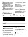
Improper installation can cause damage to
people, animals and things for which the
manufacturer cannot be considered respon-
sible
NAME:
MODEL: E -S - L
VERSIONS:
The label illustrated on the EC Declaration of Conformity of this instruction manual corresponds to the identi-
cation label placed on the machine Fig. 2. (Pos. A).
Label identication (Fig.1):
Warning signal. The instructions which refer to this signal must be followed with great care in order to
avoid accidents or damage to the machine.
This manual is an integral and essential part of the product and must be delivered to the user. The warnings
contained in it must be read carefully, as they supply important indications relating to the safety of installation,
use and maintenance. Keep this manual for future reference.
● Don’t leave the packing elements (plastic bags,
expanded polystyrene, nails, cardboard, etc.)
within the reach of children, as these elements
are potential sources of danger.
● Check that the data on the machine corresponds
to that of the electrical supply network, before
connecting the equipment.
● Adaptors, multiple sockets and /or extensions must
not be used.
● When in doubt, request a detailed diagram of the
supplied power from a qualied electrician.
The power supply must be provided with the fol-
lowing safety devices:
- efcient earthing connection;
- section of conductors suitable for absorption
capacity
- efficient earthing leakage protection circuit
breaker.
● Install the machine on a water repellent surface
(laminate, steel, ceramic, etc.) away from heat
sources (oven, cooking stove, replace, etc.) and
in conditions in which the temperature may not go
below 5°C. KEEP WARM.
● Do not leave the machine exposed to environmen-
tal elements or place them in damp rooms such
as bathrooms.
● Do not obstruct the suction or dispersion grilles
and do not cover with cloths, etc.
1 Manufacturer
2 Model and version
3 Voltage
4 EC conformity mark
5 Serial number
6 Pin
7 Machine total absorption
8 Motor power
9 Max. boiler pressure /
Max. static pressure
10 Heating element power
11 Frequency
12 Conformity marks
13 year of manufacture

56
Legend for chart above:
A Semiautomatic system; manual dispensing start
and stop.
B Automatic system; electronic control of coffee
and hot water doses dispensed.
C Number of group heads
Number of steam wands
E Number of water spouts
F Operating with economizer.
Gas heating, on request.
1 Steam tap
2 Steam wand
3 Function/service push-button panel
4 Hot water switch
5 Group head
6 Coffee dispensing push-button panel
(mod.S - E)
7 Manual water supply tap
8 Level indicator
9 Gauge
10 Power on-off switch and LED
11 Gas lighter (on specic models)
12 Valved gas tap (on specic models)
13 Switch and boiler heating element light
engagement light.
14 Programming panel (mod. E)
15 Hot water spout
16 Group head control lever (mod.L)
17 Cup heating element switch
The machines in the CLASSE 6 series have been
designed to prepare espresso and other hot beve-
rages.
A positive-displacement pump inside the machine
powers the boiler. With the push of a button water
or steam is supplied to the outlets, depending on
your needs.
The hot water used to make drinks comes from the
boiler.
The machine is composed of a steel frame on whi-
ch the mechanical and electrical components are
mounted. The side panels are made of aluminum.
The beverages are dispensed at the front of the
machine, where all the buttons, control devices and
dispensers are to be found.
There is a cup-warming plate on the top of the ma-
chine.
(Fig.3)
Models equipped with gas connections (when applied).
GROUPS
1 1 1 1
1 2 3 4
Filters 2 3 4 5
1 1 1 1
1 1 1 1
1 1 1 1
Pipe connections 1 1 1 1
Blind disks for cleaning 1 2 3 4
Plastic scoop and tamper 1 1 1 1
Instruction manual 1 1 1 1
Brush 1 1 1 1
A B C E
- ok 2 - 3 2 1
ok - 2 - 3 2 1
ok - 1 - 2 - 3 - 4 2 1

57
The machine have been designed, manufactured and
protected to be used to make express coffee and hot
beverages (tea, cappuccino, etc.). Any other use is to
be considered unsuitable and therefore dangerous.
The manufacturer cannot be held respon-
sible for any damage caused to people
or things due to unsuitable, improper or
irrational use of the machine.
The machine is equipped with the following protective
devices:
● complete panelling protection of all the parts
subject to heat and of the steam and hot water
supplier;
● cup-warmer plate supplied with a tray to collect
spilt liquids;
● work surface provided with grill and tray to collect
spilt liquids;
● expansion valve in the water system and valve on
the boiler to avoid overpressure;
● nonreturn valve on the water system to avoid
backow to the main water supply.
The safety devices provided are:
● 12V low tension push buttons an the E control key
panel;
● thermal protection on the pump motor;
● gas failure thermocouple and thermocouple ther-
mostat automatically closing gas tap;
● safe resistance thermal;
● Electronic safety devices.
Noise level in the working place does not usually
exceed 70dB(A).
The machine is supplied with rubber vibration dam-
ping feet. In normal working conditions, the machine
does not produce vibrations harmful to the operator
and the environment.
(Fig.4)
You’ll nd all the technical data on electric
connection, on the machine identication
label Fig. 1.
Machines provided with gas heating have a standard
connection kit to carry out the following connections
with:
- direct stiff pipe;
- copper and double cone pipe;
- rubber support.
Gas connections must be made in accor-
dance with all local, state and federal safety
regulations.
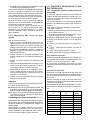
A mm 690 690 850 1090 1330
570 570 730 970 1210
B mm 505 505 665 905 1145
C mm 500 500 500 500 500
300 300 300 300 300
H mm 490 490 490 490 490
850 - 850 850 850
5 5 11 16 22
53 55 76 94 112
3/8” 3/8” 3/8” 3/8” 3/8”
Ømm drainage 14 14 14 14 14
Packaging
0.28 0.28 0.35 0,45 0,54
760x650x605 760x650x605 880x650x605 1120x650x605 1360x650x605
63 65 76 90 108
* A1(reduced overall dimensions with side case assembly)
**H1 (version lever)

58
The machine is delivered in a strong cardboard box
with internal protection.
The packaging bears symbols which must be obser-
ved during handling and stocking of the item.
Always keep the package in a vertical position
during transport. Do not turn it over or lay it
on its side and avoid bumping and exposure
to environmental elements.
The operator must always follow the instructions
contained in this manual. In the case of a failure or if
the machine is not working properly, switch it off and
do not attempt any direct repair. Refer exclusively
to a service centre.
The user must not:
● touch the hot surfaces and dispensing areas;
● place liquid containers on the machine;
● put his hands under the spouts during use;
● transport the machine or carry out maintenance
operations when the plug is connected or when
the machine is hot;
● wash the machine with water or steam jet;
● dip completely or partially the machine in water;
● use the machine if the cable is damaged;
● touch the machine when his hands or feet are wet
or damp;
● use the machine when there are children in its
proximity;
● allow the machine to be used by children or unt
people;
● obstruct the drainage of the drip tray and grill with
a cloth or anything else.
● do not use the machine when wet or very damp.
This machine may only be used with coffee. It cannot
be used for heating liquids or grinding any other kind
of product that could damage and pollute it.
The manufacturer cannot be held responsible
for damage to people or things caused by
unsuitable, improper or irrational use.
Check that the machine received corresponds to
the one indicated on the delivery note, including any
accessories.
Check that it has not been damaged during transport
and, if so, inform the forwarder and our customer
service ofce immediately.
The packing elements (plastic bags, expan-
ded polystyrene, nails, cardboard, etc.) must
not be left within reach of children as they are
potential sources of danger. Do not dispose
of the packing elements in the environment;
consign them to rms authorized for their
disposal.
The appliance is only to be installed in loca-
tions where use and maintenance is restricted to
trained personnel.
The machines are tted with height adjustable feet.
The support surface shall be levelled, dry, smooth,
steady and stable and at such a height that the cup-
warming surface is more than 150cm from the oor.
Do not use water jets or install where water jets are
used.
In order to guarantee normal operation, the machine
must be installed in areas that the environmental
temperature is between 5°C to 32°C and the humidity
is not over 70%.
It does not need to be anchored to the surface and it
does not require any technical operations to dampen
vibrations in order to operate properly.
It is recommended to leave the area around the ma-
chine free to facilitate its use and the performance
of any maintenance operations.
If the machine is wet or very damp, wait until it is
completely dry before installing or using it. It is always
necessary to have your electric service tested by a
certied electrician to ensure the machine will run at
optimal performance and no harm will come to the
machine’s electrical components.
Reserve an area near the machine for the installa-
tion of the coffee grinding and dosage machine (see
relevant documentation).
The machine is usually equipped with a water sof-
tener, type DP2 or DP4, which must be connected
by the user in compliance with the laws in force.
Should a different softener be installed, refer to the
documentation of the relevant product.
A knock box should be tted by the installer.

59
user
Electrical and water hook-ups must be in-
stalled by a personnel in full accordance with
federal, state and local laws.
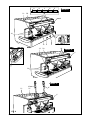
(Fig.5)
This equipment is to be installed to
comply with the applicable federal, state
or local plumbing codes.
Make sure that the maximum supply pressure
does not exceed 6.5 bar; otherwise, install a
pressure reducer.
Connections must be installed close to the machine.
● Water drainage pipe 1, having a minimum internal
diameter of 30 mm, equipped with a water-trap
accessible for inspection.
● Water supply pipe 2, with a 3/8"G cut-off tap.
Water supplies to the machine must be suitable for
consumption by man and for human uses, in com-
pliance with all the laws in force in the installation site.
The installation technician is required to get conrma-
tion from the nal owner and/or user of the system
that the water meets all the foregoing requirements.
For machine installation it is necessary to use all the
components and/or parts supplied on issue with the
machine. Should it ever be necessary to use other
parts and/or components, the installation technician
is required to verify that said other parts and/or com-
ponents are suitable for contact with water for human
consumption/drinking water. The technician in charge
of installation is required to perform all the hydraulic
connections so that they are totally compliant to all
the related rules, regulations and provisions in force
in the installation site on hygiene, hydraulic system
safety and environmental protection.
The machine with gas heating must be instal-
led in compliance with current local laws.
● Gas supply pipe 3, with a cutoff tap.
For additional information on machines equip-
ped with supplementary gas heating options,
please consult the user’s manual provided
together with the gas kit, supplied on issue
with the machine.
The machine is supplied ready for connection
according to the required electrical specications.
Before connecting the machine ensure that the plate
details comply with those of the electrical main sup-
ply.
The electrical connection cable must be directly
connected to the connection provided according to
current legislation.
The earthing and the lightening protection system
must be realized in accordance with the provisions
of current legislation.
For the main power supply be sure to use cable that is
compliant with all local, state and federal regulations
and be sure that it is properly earthed.
For three-phase power use a cable with 5 conductors
( 3 phases + neutral + earth).
For single phase power supply use a cable with 3
conductors (phase + neutral + earth).
In both cases it is necessary to provide an automatic
differential switch (Fig.5) at the start of the power cable,
complete with magnetic release elements in accord-
ance with the identication plate details (Fig. 1). The
contacts must have a 3mm or greater opening with a
dispersed current protection of 30mA.
Remember that each machine must be tted with its
own safety elements.
Should the machine’s power cable become
damaged it is to be replaced by the manu-
facturer or by a factory trained and certied
technician, in order to prevent any risks.
(Fig.6)
This connection is ABSOLUTELy NECES-
SARy and must be made right after the machines
is installed.
Connect an earthing wire to the terminal clip which is
located underneath the base of the machine.
Be sure that this wire and the connection are per-
formed in accordance with federal, state and local
regulations.
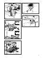
(Fig.7)
The lever should be assembled during installation
of the machine.
To carry out this operation, assemble the upper case
according to the instructions in Fig.7 (1 and 2).
Fix the case by tightening the screws and then screw
the lever in the upper part.

60
OPERATION
(Fig.8)
Two-position switch with LED..
Turn on the switch (LED. on) the machine is turned
(apart from the boiler) and the pump is turned on
to ll the boiler;
Two-position switch with LED.
Upon activating the switch (LED on) the power is
supplied to the heating elements in the boiler. .
Two-position switch with LED
By turning on the switch (LED on), the power is
supplied to the cup warmer heating element.
(mod.S)
Two-position switch:
With switch ON, coffee is dispensed;
With switch OFF, dispensing of coffee is interrupted.
(mod. E)
Five buttons with corresponding LEDs:
A Press the button for a second, LED on, release
button; a small coffee is dispensed.
The LED turns off and dispensing stops.
B Press the button for a second,LED on, release
the button; two small coffees dispensed from the
same unit.
The LED turns off and dispensing stops.
C Press the button for a second, LED on, release
the button; a big cup of coffee is dispensed.
The LED turns off and dispensing stops.
Press the button for a second, LED on, release
the button; two big cups of coffee are dispensed
from the same unit.
The LED turns off and dispensing stops.
E Press the button for a second, LED on, release
the button; coffee is continuously dispensed.
Press the button for a second, LED off, release
button; continuous dispensing of coffee stops.
To interrupt brewing once the operation has been
activated with buttons , press the same
button again or press E.
(mod.L)
The lever is usually placed in an upward posi-
tion.
Activate the lever by pushing it down to obtain
coffee dispensing.
(mod.S)
Hot water switch with two positions:
With switch ON, the LED ashes and hot water is
dispensed directly from the boiler.
With switch OFF, the LED switches off and dispen-
sing stops.
(mod.E)
When the button is pressed, hot water is dispensed
up
● Position the machine unit onto the horizontal sur-
face provided for that purpose and adjust the base
feet to ensure that the machine is stable and that
vibrations are limited.
Before connecting the machine, thoroughly ush the
main water supply pipes:
● Open the main water supply taps and let the water
run at full pressure for several minutes.
● Connect to the main water supply.
● Connect the machine up to the power supply
mains.
● Connect the gas pipe.
Thoroughly ush all the water pipes of the machine:
● Leave the water supply taps running at full pres-
sure.
● Switch on main switch 1 (Fig.8): wait until the boiler
lls up to the set level.
● Switch on boiler heating element switch 2 (Fig.8)
to begin heating the water in the boiler.
● Once standard machine work conditions have been
reached with the machine in “ready for operation”
mode, switch the machine off and empty all the wa-
ter lled into the water circuit the rst time, thereby
eliminating any possible initial impurities.
● Fill the machine up with water again and set it into
standard operation mode.
● Once the “ready for operation” status is reached:
- Connect the lter-holders to the dispenser units
(without coffee); operate each group head in
order to allow the water to escape for about one
minute.
- Dispense hot water until at least 2 liters of water
have been dispensed from the 1-group or 2-groups
compact, 5 liters from the 2-groups machines, 8
liters from the 3-groups machines and 11 liters
from the 4-groups machines.
- Open each steam dispensing point for 1 whole
minute.
Once installation is terminated, the installa-
tion technician MUST issue an installation
report.

61
WATER CHANGES: at the start of each daily activity
and anyway always after machine stop periods
longer than 8 hours, it is necessary to change
100% of the water contained in the circuits via the
points appropriately provided on the machine for the
purpose.
USING THE STEAM WAND: Before using the steam
wand, it is always necessary to ush out all the resi-
dual steam condensate for at least 2 minutes.
The machine has a top shelf on which the cups are
kept and heated, ready for use.
This is very important to obtain good coffee as the
pre-warmed cup stops the coffee from growing cold
too quickly.
● Remove the lter-holder from the group head and
knock out any grounds into a knock box. Be careful
not to damage the rim of the lter.
● Use the lter for 1 or 2 coffees, according to your
need.
● Fill the lter with the measure of coffee, level it off
and press it down gently with the tamper.
● Remove any ground coffee that has stuck to the
rim of the lter during tamping.
If ground coffee is left on the rim of the lter, the
lter-holder will not seal properly in the group
head, and during coffee production, water or
coffee grounds may leak into the cup.
(Fig.8)
● Turn on the water supply tap 2 (Fig.5).
● Turn on the gas tap 3 (Fig.5).
●Turn the main switch 1; the pump is activated,
lling the boiler.
● When the correct level is reached, the pump stops.
Turn on Switch 2 in order to activate the heating
element in the boiler.
● Turn the gas tap 8 to the vertical open position
and hold down the corresponding button, at the
same time repeatedly press hard on the piezoe-
lectric button 9 until the spark lights the gas ame
(carry out this operation looking through window
12). Hold the tap button 8 down for approx. 30
seconds to allow the safety system to keep the
ame lighted.If the ame goes out, repeat the
operation.
Should the ame not light quickly within a few
seconds, please close the gas tap by turning
it 90° in a clockwise direction.
● Wait until the machine reaches its working pres-
sure and until the correct thermal balance is
achieved.
● Turn on the water supply tap 2 Fig.5.
● Turn the main switch 1; the pump to ll the boiler
will activate.
● When the water reaches the correct level, the
pump stops.
Turn the main switch 2 to begin heating the water
in the boilerthen turn on each group head until
water begins to ow from them.
●
Wait for the machine to reach its working pressure
and to reach the correct thermal balance.
● For lever models without pump, machine starting
is identical, the heater will be lled by the water
supply pressure.
directly from the boiler for the set time or until the
button is pressed again.
If you press the button for 2 seconds, dispensing
is continuous and only stops when the button is
pressed again.
Dispensing is discontinued automatically after 30
and 60 seconds, respectively.
(mod.L)
Tap: turn in a anticlockwise direction to open and
a clockwise direction to close
Dispensing cannot be carried out if the machine
has not reached the operating pressure or tempe-
rature at least once, and each time that the boiler
pressure drops too much.
Tap: turn in an anticlockwise direction to open and
a clockwise direction to close.
-
Press down to ll the boiler.
(models with gas hea-
ting).
Open: vertical position;
Closed: turn 90° in clockwise direction.
(models with gas hea-
ting).
Ignition button: press down rmly to give off the
spark to light the gas for the burner.
(Fig.8)
with mobile needle on a xed dial with a
double scale.
Visual control of the pump (lower manometer ) and
of the boiler pressure (upper manometer) (mod.
E-S).
Minimum and maximum water level indicator .
Visual control of water level in boiler.
(models with gas heating).
Visual control of lighting and functioning of the
ame of the gas burner.

62
● Immerse the steam wand into the liquid to be
heated.
● Gradually turn on the steam knob 6 (Fig.8); the
steam that bursts in the liquid heats it to the desired
temperature.
● Turn off the steam knob when the desired tempe-
rature has been reached.
Immediately after carrying out this operation,
clean the wand with a sponge or clean cloth.
Be careful as the wand is hot and may burn
your hand.
● Place the jug under the hot water spout and use
the delivery control according to the model (Fig.8).
When the desired quantity has been obtained, turn
off the switch.
● Add the beverage desired.
For these models, hot water is dispensed in specic
quantities (see paragraph 9, adjusting the dose of
hot water).
When puried water is used, these beverages often
assume a darker colour.
Should the user prefer a lighter coloured drink, draw
fresh water from an ordinary tap and proceed with
the steps for heating a beverage as described in
point 8.3.
(Fig.8)
With the Model E it is possible to programme the
buttons to dispense a set amount of coffee and hot
water (if this function is enabled).
The quantity of coffee and hot water dispensed can
be adjusted using the push-button panel or the hot
water controls.
1 Press the button E on the left push-button panel
and hold it down for 8-10 seconds until water stops
owing from the group head and the LED light of
the rst button on the left begins ashing.
2 It is necessary to act as to make 1 or 2 cups in or
-
der to reach the correct coffee amount adjustment
in the cup.
3 Put the lter-holder (containing ground coffee) into the
left group head and place a cup under the spout.
4 Press the button you would like to programme (i.e.
button A for one small cup).
5 Once the desired amount of coffee has been poured,
press the button A to stop the ow of coffee. The ma-
chine will save this quantity.
6 Pressing the button E again, the LED light will turn
off and the machine will store the new quantity.
● Lock the lter-holder into the group head rmly to
obtain a leaktight seal.
● Place the cups under the spouts and start pouring
using control 3 - 4 or push-button panel 5 accor-
ding to your model (Fig.8).
● When the coffee has been poured, leave lter-
holder in the group head until it’s time to produce
another coffee.
Great tasting espresso begins with proper
grinding. High quality espresso shots should
take an average of 25-30 seconds to pro-
duce.
If the coffee is ground too coarsely, the espresso will
be pale in color and weak in avor, with only a very
small amount of crema. If coffee is ground too ne,
it will be dark in color and have no crema.
Another important factor to consider is the freshness
of your coffee beans. Good espresso can only be
made if your beans are freshly and uniformly ground.
The grinder blades should be sharp and the dosing
mechanism of your grinder should be adjusted so that
it measures approximately 6 grams per pull.
It is important to grind your coffee fresh each time
you produce an espresso because once the beans
are ground they rapidly lose their aromatic qualities
and the oils in the beans begin to go rancid.
(Fig.8)
Espresso machine with mechanical groups and xed
dosing. Pull down on the group control lever (4C).
Wait for coffee to begin to pour into the cup: Release
the lever and let it lift up by itself.
To make 2 coffees, repeat this operation for the
second time.
CAUTION: do not pull down on the lever if
there is no coffee in the lter-holder.
(Fig.9)
● Pour an espresso in your cappuccino cup.
● Use a tall and narrow jug, ll it half-way with fresh
milk.
●
Place the jug under the spout so that the nozzle
touches the bottom.
● Turn on the steam knob and lower the jug so that
the nozzle is almost at the surface of the milk to
create froth.
● Turn off the steam knob and pour the milk into the
cup.
Immediately after carrying out this operation,
clean the wand with a sponge or a clean
cloth so that the milk does not dry on it. Be
careful as the wand is hot and may burn
your hand.

63
7 Make a coffee by using the button you program-
med and be sure the system stored the correct
parameter.
If some doses have to be changed (),
once at point 5 repeat steps 3-4-5 for each dose.
Remember to use the correct lter-holder with rele-
vant lter and be sure to use freshly ground coffee.
Then carry out point 6 and repeat point 7 to check
all changed doses.
If all group heads are to be programmed with the
same doses, the programming of coffee doses is
nished. If the dosage of another group heads is to
be changed (1-2-3-4 doses), proceed as indicated
in the above-mentioned point 1-7, Use the push-
button panel of the corresponding group head to
programme.
Proceed as follows:
1. Press and hold the button E of any push-button
panel, for 8-10 seconds until water stops owing
from the group head and the LED of the button E
on the left group head’s push-button panel starts
ashing. The machine is now ready to accept
quantity variations.
2. Put a cup or jug beneath the water spout (Fig. 3).
3. Push the hot water button (5B).
4. Once the desired quantity of water has been
delivered, press the hot water button (5B) again.
Water will stop pouring and the quantity will be
saved.
5. Once programmed, press the button E again and
the LED will go out and the machine will store the
new quantity.
6. Double check that programming is correct by
producing a hot water drink.
Hot water may also be dispensed by:
● press and hold the hot water button (5A or
5B) for at least 2 seconds: when the button is
released, the machine will dispense hot water
continuously;
● to manually stop the dispensing, press the hot
water button (5A or 5B) again.
(Fig.10)
If space is limited, two smaller side tray casing pieces
are available. These pieces replace the existing side
tray casings.
To replace the side tray casings, unscrew the 3
screws (Fig. 10), remove the side casing and replace
it with the smaller one. Do this for both the left and
right sides of the machine.
button panel
With the board E06 it is possible to regulate the boiler
pressure directly from the push-button panel, elimi-
nating the need for a technician to open the machine
and change the electronics internally.
This is possible thanks to an electronic pressure tran-
sducer that detects heater pressure in real time.
To enter the regulation menu proceed as follows:
- Switch off the machine.
- While holding down the button E of the rst group
turn the machine on (g. 8).
- Buttons A and B will light up to indicate 1 bar (the
default setting) of pressure.
In this menu, only buttons (g. 8) of the
rst group are active with the following functions:
A = Button + (pressure increase with 0.1-bar step).
B = Button – (pressure decrease with 0.1-bar
step).
C = 1 bar (factory set at 1 bar).
= ESC (regulation save and exit from menu).
To increase pressure
Press button A, considering that each time it is pres-
sed, heater pressure increases by 0.1-bar step up to
a maximum 1.4 bars.
Pressure increases instantly (regulation visible by
means of boiler pressure gauge).
To decrease pressure
Press B, considering that each time it is pressed
pressure decreases in real time by 0.1 bar step to a
maximum of 0.6 bars.
Opening the steam head, the new pressure regulation
can be assessed immediately by means of the heater
pressure gauge.
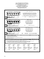
Buttons A and B ash to indicate setting of Boiler
pressure as follows:
BUTTON A
BUTTON B
PRESSURE
[bar]
ON 4 ashes 0.6
ON 3 ashes 0.7
ON 2 ashes 0.8
ON 1 ash 0.9
ON ON 1.0
1 ash ON 1.1
2 ashes ON 1.2
3 ashes ON 1.3
4 ashes ON 1.4

64
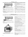
A = push-button panel/LED (pressing each button,
the corresponding LED ashes)
B = volumetric meter group 1 (100-pulse supply)
C = volumetric meter group 2
(100-pulse supply) (*)
= volumetric meter group 3
(100-pulse supply) (*)
E = heater level (water charge if level is not
sufcient)
F = pressure transducer (heating element ON until
boiler pressure set-point is reached)
(*) Only for predisposed machines.
(**) Only for machines with star resistance connec-
tion.
Some of the auto-test operations involve the
dispensing of hot water and steam; take care
in order to avoid possible burns.
Push buttons A or B (g. 8) to scroll through display
numbers and letters. Once you reach the desired
letter or number (component you wish to control)
press button C to activate.
Button D stops activation of the component.
To quit auto-test menu switch off the machine then
switch on again.
Note: Press esc to quit operations and F
During auto-test, brewing will be interrupted and the
boiler will not be lled (except for test F).
Electronic card E 06 allows the operation of dia-
gnostic programming with which possible machine
failures or malfunctions can be signalled.
In order to utilise this function it is necessary to ac-
cess the electronic card by dismantling the left panel
of the machine (a descriptive label of the auto-test
function is attached to the inside of the panel).
As the use of diagnostic programming is
conducted with the machine open, be careful
not to touch any live parts.
Malfunctions are shown on the display situated at
the centre of the electronic board.
By pressing button C, the machine returns to the
default factory setting of 1-bar of pressure.
After having regulated the desired pressure, press
button to save the setting and quit the menu.
ATTENTION: during programming, water dispen-
sing is interrupted while boiler pressure control is
in use.
The electronic board E06 enables techni-
cians to individually test and verify the operation of
all electronic components of the machine.
In order to utilise this function it is necessary to enter
the electronic board by dismantling the left panel
of the machine (a descriptive label of the auto-test
function is attached to the inside of the panel).
The sequence is guided by means of the display at
the centre of the electronic board.
Since the auto-test is conducted with machine
open, be careful not to touch any live part.
To enter the auto-test menu proceed as follows:
- Switch off the machine.
- Push and hold button A of the rst group’s push-
button panel (g. 8) and turn on the machine.
- Buttons
and (g. 8) light up and the
board display indicates 0 (auto-test menu in ope-
ration).
In this menu only buttons of the rst group
operate with the following functions:
A = Button + (increases the number/letter correspon-
ding to the component to be activated).
B =Button – (decreases the number/letter correspon-
ding to the component to be activated).
C = Enter (component activation).
= ESC (quit component activation).
During activation of the component, the display point
will ash.
Each value indicated on the display corresponds to
the auto-test of the following components:
= auto-test ON
= electro-valve group 1 (ON for 3 seconds)
= electro-valve group 2 (ON for 3 seconds) (*)
= electro-valve group 3 (ON for 3 seconds) (*)
= electro-valve hot water supply
(ON for 3 seconds) (*)
= electro-valve charge (ON for 3 seconds)
= pump motor (ON for 3 seconds)
= 1st heating element (ON for 5 seconds) (**)
= 2nd heating element (ON for 5 seconds) (**)
= 3rd heating element (ON for 5 seconds) (**)

65
Operations to be carried out with the machine
operative and under pressure.
● Assemble the lter membrane supplied with the
machine onto the lter-holder, and add a spoonful
of detergent powder for coffee machines, then as-
semble the lter-holder in the set to be cleaned.
● Operate the coffee dispenser button for about 30
seconds.
● Stop and start the dispenser function until clean
water begins to descend from the unit discharge
pipe.
● Dismantle the lter-holder, remove the lter mem-
brane, re-assemble the lter holder onto the unit
and then undertake the dispensing operation
several times in order to rinse.
● Make a coffee in order to eliminate any unpleasant
tasting residues.
(available only on S
models)
● Enter the automatic washing mode by keeping the
coffee dispensing button pressed for at least 5s:
and the led will slowly ash alternating orange and
blue.
Maintenance operations have to be carried
out when the machine is off and cold and
the plug is disconnected. Some particular
operations have to be performed when the
machine is operating.
Do not clean the machine by using metal or
abrasive devices, such as steel wool, metal
brushes, needles, etc. or general detergents
(alcohol, solvents, etc.)
When necessary, use special detergents
for coffee machines that can be bought in
specialized service centres.
(Fig.11)
Use a clean cloth or sponge that does not leave any
lint (preferably cotton or linen).
● Carefully clean the outside surface, following the grain
of the satin nish on the parts in stainless steel.
● Clean the steam wand and hot water outlet and
check that the nozzles are not encrusted (if they
become encrusted, be careful not to deform or
damage them).
● Clean the outlets and the seals under the casing of
the group heads using the special brush supplied
(Fig.12).
● Remove the lter-holders and remove the lter
and the clamp which secures the lter, use a bru-
sh to remove any coffee deposits and rinse with
hot water in order to dissolve any coffee bean oil
residue.
Failures are indicated on the electronic board display
by means of numbers or letters. If there is more than
one failure, they are displayed one after the other.
= Time-out boiler lling level: time limit for correct
boiler lling has been exceeded.
= Time-out boiler pressure set-point: the time
limit to reach boiler pressure set-point has been
exceeded
= Electronic board E06 12Vdc short: short circuit
in the electronic board E06
= Capacity level sensor 12Vdc short: capacity level
sensor supply has short-circuited. (*).
= Pressure transducer 12Vdc short: pressure tran-
sducer supply has short-circuited.
= Volumetric counter 12Vdc short: short circuit on
the supply of volumetric counters.
= 5Vdc push-button panel short: the push-button
panel has short-circuited.
= Transducer/probe short on output signal: short
circuit on output signal from the pressure tempe-
rature probe / transducer.
= Open transducer/probe signal: the output signal
from the temperature probe/transducer has been
interrupted.
A = Absence of volumetric counter impulses group
1: the volumetric counter of the rst group is not
transmitting impulses to the electronic board.
B = Absence of volumetric counter impulses group 2:
the volumetric counter of the second group is not
transmitting impulses to the electronic board (*).
C = Absence of volumetric counter impulses group
3: the volumetric counter of the third group is not
transmitting impulses to the electronic board (*).
(*) Only for predisposed machines.
The failures identified by numbers 1 to 9 block
machine operation. Apart from the failure being in-
dicated on the display, the push-button panel LED
will ash simultaneously informing the user of the
malfunction.
After having identified and resolved the failure,
switch the machine off and then on again for normal
operation
NOTE: The problems identied with the letters A, B
and C do not interrupt the functions of the machine.
They are identied on the display and during dispen-
sing from the corresponding group, the LED of the
button pressed will ash.

66
and repairs
During all maintenance / repair operations, the
components used must be warranted to maintain
all the machine’s hygiene and safety requirements.
Using the machine’s original spare parts constitute
an effective warranty.
After repair or component replacement operations
involving parts coming into contact with water and/or
food, it is necessary to run the machine washing
procedure as specied under the installation and
rst-time start-up section herein.
Have been tted with economizers which do not
draw water from the boiler to make hot water, the
water in the boiler need only to be renewed from
time to time.
(Fig.13)
Must be performed by a certied factory trained
technician only.
● Turn off the machine and wait for the pressure in
the boiler to diminish (gauge needl on “0”).
● Dismantle the reservoir by working on the screws
(Fig. 10)
● Insert a rubber hose into the hose-end tting (3)
(Fig.13)
● Use the wrench (1) to immobilize the tting (2) and
loosen the hose-end tting (3).
● Allow the water to ow out completely; then, close
the tting (3) and remove the rubber hose.
● Rell the boiler (paragraph 7.3.).
Whenever descaling operations are ne-
cessary, ensure that only specic products
suitable for parts contacting water for public,
human consumption are used. Make sure
that all the relative product instructions are
carefully observed and complied with at all
times.
Fig.12)
Operation to be carried out when the machine is off
and cold.
● Prepare a solution of 4 packages of detergent
powder Code dissolved in a litre of
boiling water in a stainless steel, plastic or glass
recipient ().
● Remove the lters and immerse them with the lter
holders in the prepared solution, leaving them for
at least 10/20 minutes (all night is better).
● Remove them from the container and rinse them
thoroughly in running water.
● Remove the cup-holder grid 1 (Fig. 11) and clean
discharge 2 (Fig. 11)
Stage
Wa i t – Re a d y f o r
washing
SLOW ashing orange
+ blue
Washing in progress Orange + 1 FLASHING
blue
Wait – Ready for rin-
sing
FAST flashing orange
+ blue
Rinsing in progress Orange + 2 FLASHING
blue
● Insert the blunt lter membrane inside the lter-
holder and then add a spoonful of coffee machine
detergent powder and then assemble the lter-
holder onto the unit to be cleaned.
● Activate the washing phase by pressing the coffee
dispensing button. The machine will undertake
10 washing cycles lasting 10s each with a 10s
interval the led will be orange colour with a short
blue ashing interval in between.
● At the end of the washing operation the machine
goes into l stand-by and the led will begin to ash
rapidly alternating orange and blue. Dismantle
the lter-holder remove the lter membrane and
then re-assemble the whole thing.
● Enable the rinse function by pressing the coffee
dispensing button. The machine will undertake 3
rinse cycles lasting 30s each followed by a 10s
pause, the led will be orange with a short blue
ashing interval.
● At the end of the cycle the led switches off and
the machine is ready for a new coffee dispensing
operation.
Note: it will be possible to interrupt both the washing
and the rinsing stages by pressing the coffee
dispensing button twice, in the rst case the
machine will go on to the stand-by stage ready
for rinsing, while in the second case it returns to
the normal ready-for-use mode.

67
● Carry out cleaning and maintenance operations.
● Wind up the cable and fasten it to the machine
with sticky tape.
● Cover the machine and place it in a dry room. Do
not leave it exposed to environmental elements
and do not allow it to be touched by children or
untrained persons.
To disconnect from the main power supply, consult
qualied personnel.
● Besides carrying out the operations necessary for
a temporary stop, cut off the cable, pack the ma-
chine in cardboard, polystyrene or other packing
material and consign it to rms authorized for its
disposal or to a resale dealer.
Check operations to be carried out by the
user with the plug disconnected.
For any type of problem or inconvenience not
specically indicated, disconnect the plug and
contact our service centre. Do not attempt to
perform any direct repairs.
A) The machine does not start:
- check that the plug is connected;
- In case of power failure wait for the power to return
and check if the earthing protection circuit breaker
or the main switch is on;
- check the condition of the plug and the supply
cable; if damaged have them replaced by qualied
personnel.
B) There is water under the machine:
- check that the drainage tray is not obstructed.
C) Slow dispensing:
- check that the lters and group heads are clean;
- check that the coffee is not too nely ground.
D) Irregular steam delivery:
- check that the steam wand tip is not obstructed.
Page is loading ...
Page is loading ...
Page is loading ...
Page is loading ...
Page is loading ...
Page is loading ...
Page is loading ...
Page is loading ...
Page is loading ...
Page is loading ...
Page is loading ...
Page is loading ...
Page is loading ...
Page is loading ...
Page is loading ...
Page is loading ...
Page is loading ...
Page is loading ...
Page is loading ...
Page is loading ...
Page is loading ...
Page is loading ...
Page is loading ...
Page is loading ...
Page is loading ...
Page is loading ...
Page is loading ...
Page is loading ...

96
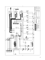
SCHALTPLANE
CA = Centralina autolivello Controle de niveau Wasserniveaukont Water level control Transd. autonivel Central auto nível
de l’eau rolle
CPU = Scheda CPU Fiche CPU Karte CPU CPU Board Tarjeta CPU Placa CPU
= Contatore volumetrico Compteur volumetrique Volumenzaehler Flow Meter Contador volum. Contador volumétrico
EA = Elettrovalvola acqua Electrovanne eau Wasserelektroventil Water electrovelve Electrovalvula agua Válvula Elétrica da água
EAR = Elettrovalvola aria Electrovanne air Luftelektroventil Air electrovalve Electrovalvula aire Válvula Elétrica do ar
EC = Elettrovalvola carico Electr. de chargement Speisungselektroventil Feeding electrovalve Electrovalv. carga Válvula Elétrica abast.
EE = Elettr. Economizzatore Electr. economizeur Ekonomiserelektroventil Economizer electr. Electr. Economizador V.Eletr. Economizador
EG = Elettrovalvola gruppo Electr. du groupe Gruppeelektroventil Group Electrovalve Electrovalvula grupo Válvula Elétrica grupo
= Elettrovalvola vapore Electrovanne vapeur Dampfelektroventil Steam valve Electrovalvula vapor Válvula Elétrica vapor
F = Fusibile Fusible Sicherung Fuse Fusible Fusível
IG = Interruttore generale Interrupteur general Hauptschalter Main switch Interruptor general Interruptor geral
= Interruttori gruppo Interrupteurs groupe Gruppenschalter Group switches Interruptores grupo Interruptores do grupo
IA = Interruttori acqua Interrupteurs eau Wasserschalter Water switches Interruptores agua Interruptores da água
IR = Interruttore Resistenza Interrupteur resistance Heizungsschalter Resistance Switch Interruptor resist. Interruptor da Resist.
IS = Interruttore scaldatazze Interrupteur chauffe Schalter Tassenwärmer Cup heating switch Interruptor calienta Interruptor aquec.
tasses tazas xícaras
LC = Lampada livello Lampe niveau Lampe für Wasserstand Level lamp Lámpara de nivel Lâmpada nível
= Morsettiera allacciam. Boit a bornes pour Anschhlussklemmleiste Mains Power Bloque de terminales Conj. bornes ligação
branchement Connection
= Motore pompa Moteur pompe Pumpen motor Motor Pump Motor bomba Motor da bomba
= Micro Relé pompa Micro Relé pompe Micro Relé pumpen Pump micro Comtactor Micro Relé bomba Micro Relé bomba
= Morsetto di terra Borne du sol Erdklammer Earth connection Conexion de tierra Borne do terra
P = Pressostato Pressostat mecanique Mech. druckwaechter Mechanic pressure Presostato mecanico Interrup. Mec. Pressão
switch
RC = Resistenza caldaia Resistance chaudiere Kesselheizung Boiler Heating Resist. Resist. Caldera Resistência da caldeira
RP = Relé pompa Relé pompe Relé pumpen Pump contactor Relé bomba Relé bomba
RR =
Relè macanza acqua Relé manque d’eau Relé Kein Wasser Water shortage relè Relé falte de agua Relé falta de água
RS = Resistenza scaldatazze Resistance chauffe Tassen warmerheizung Cups Heating Resist. Calienta tazas Resistência aquec.
tasse Resistance xícaras
SA = Scheda autolivello Carte autoniveau Wasserstandkarte Autolevel board Ficha de autonivel Placa auto nível
SL = Sonda Livello Sonde niveau Standfühler Level feeler Sonda nivel Sonda nível
SP = Sensore di pressione Capteur de pression Drucksensor Autolevel board Detector de presión Sensor de pressão
ST = Sonda temperatura Sonde Temperature Temperatur Sonde Temperature Probe Sonda de temp. Sonda temperatura
STS = Sonda temp.TS/TSC Sonde Temperature Temperatur Sonde Temperature Probe Sonda de temp. Sonda temperatura
TS/TSC TS/TSC TS/TSC TS/TSC TS/TSC
TA = Tasto acqua Touche eau Wassertaste Key water Tecla agua Tecla água
TF = Tastiera funzioni/servizi Clavier function/service Funktion/Dienst druck Function/service Botonera/Funciòn/ Teclado funções/
keyboard servicio serviços
TG = Tastiera gruppo Clavier groupe Gruppedruckknoepfe Group Keyboard Botonera grupo Teclado grupo
= Trasformatore transformateur Transformator Transformer Transformador Trasformador
TP = Tastiera programmazione Clavier de programmation Programmiertastatur Program Keyboard Botonera programación Teclado programação
=Teleruttore Télérupteur Fernschalter Transformer Telerruptor Contador
TS = Termostato di sicurezza Thermostat de sécurité Sicherheitsdruckwächter Safety thermostat Termóstato de seguridad Termostato de segurança
TTSC = Tastiera TSC
Clavier TSC Tastatur TSC TSC keyboard Botonera TSC Teclado TSC
= Pompa a vibrazione Pompe à vibration Vibrationspumpe Vibration pump Bomba de vibración Bomba com vibração
AR = Arancio Orange Orange-farbig Orange Naranja Laranja
B = Blu Bleu Blau Blue Azul Azul
BI = Bianco Blanc Weiss White Blanco Branco
BIB = Bianco-Blu Blanc-Bleu Weiss-Blau White-Blue Blanco-Azul Branco-Azul
BIN = Bianco-Nero Blanc-Noir Weiss- Braun White-Black Blanco-Negro Branco-Preto
G = Giallo Jaune Gelb Yellow Amarillo Amarelo
= Giallo-Verde Jaune-vert Gelb-gruen Yellow-green Amarillo-verde Amarelo-Verde
GR = Grigio Gris Grau Grey Gris Cinza
= Marrone Marron Braun Brown Marron Marrom
N = Nero Noir Schwarz Black Negro Preto
R = Rosso Rouge Rot Red Rojo Vermelho
RO = Rosa Rose Rosa Rose Rosado Rosa
= Verde Vert Gruen Green Verde Verde
= Viola Violette Violett Violet Morado Roxo
Page is loading ...
Page is loading ...
Page is loading ...

100
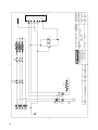
COLLEGAMENTO ELETTRICO
BRANCHEMENT ELECTRIQUE
STROMANSCHLUSS
ELECTRONIC CONNECTION
CONEXION ELECTRICA
LIGAÇÃO ELÉTRICA
346V ÷ 400V / 3N~
COLLEGAMENTO TRIFASE A STELLA CON NEUTRO
BRANCHEMENT TRIPHASE EN ETOILE AVEC NEUTRE
DREIPHASIGER STERN ANSCHLUSS MIT MITTELEITER
THREE-PHASE STAR CONNECTION WITH NEUTRAL
CONEXION TRIFASICA A ESTRELLA CON NEUTRO
LIGAÇÃO TRIFÁSICA EM FORMA DE ESTRELA, COM NEUTRA
2 GR. H07RN-F 5x2,5 mm
2
200V ÷ 240V
COLLEGAMENTO MONOFASE
BRANCHEMENT MONOPHASE
EINPHASINGER ANSCHLUSS
SINGLE-PHASE CONNECTION
CONEXION MONOFASICA
LIGAÇÃO MONOFÁSICA
2 GR. H07RN-F 3x2,5 mm2
120V~ / 220V~ U.S.A.
COLLEGAMENTO MONOFASE
BRANCHEMENT MONOPHASE
EINPHASINGER ANSCHLUSS
SINGLE-PHASE CONNECTION
CONEXION MONOFASICA
LIGAÇÃO MONOFÁSICA
2 GR. 100V÷120V~ SO, SJO, SJTO 3x10 AWG
2 GR 200V÷240V~ SO, SJO, SJTO 3x12 AWG
L3 L2 L1 N
L N
N V-GVBI
IL CONDUTTORE DI TERRA (GV) DEVE ESSERE PIU' LUNGO DI 9 cm RISPETTO AI RIMANENTI
THE EARTH CONDUCTOR (GV) MUST BE LONGER THAN THE OTHERS OF 9 cm
DER ERD STROMLEITER MUSS LAENGER ALS 9 cm IN BEZUG AUF DEN RESTLICHEN STROMLEITER SEIN
LE CONDUCTEUR DE TERRE DOIT ETRE PLUS LONG DE 9 cm PAR RAPPORT A LES AUTRES
LA LONGITUD DE LA TOMA DE TIERRA TIEN ESSER SUPERIOR A 9 cm RESPECTO AL RESTO
O FIO TERRA (GV) DEVE SER 9 cm MAIS COMPRIDO DO QUE OS RESTANTES
M = MARRONE MARRON BRAUN BROWN MARRON MARROM
N = NERO NOIR SCHWARZ BLACK NEGRO PRETO
B = BLU BLEU BLAU BLUE AZUL AZUL
BI = BIANCO BLANC WEISS WHITE BLANCO BRANCO
V = VERDE VERT GRUEN GREEN VERDE VERDE
GV = GIALLO-VERDE JAUNE-VERT GELB-GRUEN YELLOW-GREEN AMARILLO-VERDE AMARELO-VERDE
BIN = BIANCO-NERO BLANC-NOIR WEISS-SCHWARZ WHITE-BLACK BLANCO-NEGRO BRANCO-PRETO
BIB = BIANCO-BLU BLANC-BLEU WEISS-BLAU WHITE-BLUE BLANCO-AZUL BRANCO-AZUL
VI = VIOLA VIOLET VIOLET VIOLETT VIOLETA ROXO
R = ROSSO ROUGE ROT RED ROJO VERMELHO
PONTICELLI FORNITI IN DOTAZIONE
JUMPERS ARE WITH THE SUPPLIED
ZUSATZBRUCKEN SIND IN AUSSTATTUNG
PONTETS INSERES DANS LA DOTATION
PUENTES ESTAN INCLUIDOS EN EL MATERIAL DE DOTACION
PONTINHAS FORNECIDAS
L3 L2 L1 N
L N
M GVB
B
L3 L2 L1 N
R S T N
NM GR GV
Page is loading ...

102
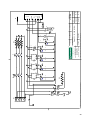
E
1) Collegare il cavo alimentazione come indicato in
gura.
2) Spostare il collegamento delle resistenze dal con-
nettore siglato 3VN~ in quello 3V~ sulla scheda di
potenza
1) Raccorder le câble d’alimentation comme indiqué
dans la gure.
2) Déplacer le raccordement des résistances du
connecteur avec sigle 3VN~ dans celui 3V~ sur la
carte de puissance
L3 L2 L1 N
R S T N
NM GR GV
L3 L2 L1 N
R S T N
NM
GR
GV
R
S
T
S - L
1) Das Versorgungskabel anbringen, wie es auf der
Abbildung angegeben ist.
2) Die Verbindung der Widerstände von Verbinder
3VN~ auf Verbinder 3V~ auf der Leistungskarte
umstecken.
1)Connect cable as shown in the picture.
2) On the power board, move resistance connection from
connector marked 3VN~ to connector marked 3V~
1) Conectar el cable de alimentación como se ilustra
en la gura.
2) Cambiar la conexión de las resistencias del conector
con la sigla 3VN~ a 3V~ en la tarjeta de potencia.
1) Ligar o o de alimentação como indicado na gu-
ra.
2) Transferir a ligação das resistências do conector
siglado 3VN~ para àquele 3V~ na placa de potên-
cia.
1) Collegare il cavo alimentazione come indicato in
gura.
2) Scollegare i cavi azzurri (neutri) dalla resistenza
elettrica ed isolarli.
3) Collegare la resistenza elettrica della caldaia se-
condo lo schema sopra riportato.
1) Raccorder le câble d’alimentation comme indiqué
dans la gure.
2) Débrancher les câbles bleus (neutres) de la rési-
stance électrique et les isoler.
3) Raccorder la résistance électrique de la chaudière
selon le schéma reporté ci-dessus.
1) Das Versorgungskabel anbringen, wie es auf der
Abbildung angegeben ist.
2) Die blauen Kabel (Nullleiter) vom elektrischen
Widerstand abtrennen und isolieren.
3)Den elektrischen Widerstand des Kessels an-
schließen, wie es weiter oben abgebildet ist.
1)Connect cable as shown in the picture.
2) Disconnect the light blue cables (neutral) from
electric resistance and insulate them.
3) Connect boiler electric resistance according to the
diagram below.
1) Conectar el cable de alimentación como se ilustra
en la gura.
2) Desconectar los cables azules (neutros) de la resi-
stencia eléctrica e aislarlos.
3) Conectar la resistencia eléctrica de la caldera según
el esquema que se ilustra arriba.
1) Ligar o o de alimentação como indicado na gu-
ra
2) Desligar os fios azuis (neutros) da resistência
elétrica e isolá-los
3) Ligar a resistência elétrica da caldeira, segundo o
esquema acima.
Page is loading ...
Page is loading ...
Page is loading ...
Page is loading ...

HEADQUARTERS & PRODUCTION PLANT
Rancilio Group spa
Viale della Repubblica 40
20010 Villastanza di Parabiago
Milano Italy
Ph. +39 0331 408200
Fax +39 0331 551437
www.rancilio.com
www.egrocoffee.com
Worldwide Branch Locations
SPAIN
Rancilio Espana, s.a.
Gran Vía de Carlos III, 84 3ª
Edicio Trade
08028 Barcelona Spain
Ph. +34 902 884 275
Ph. +34 934 923 414
Fax +34 93 496 57 01
www.rancilio.com
PORTUGAL
Rancilio Portugal Lda
Estrada da Falagueira nº 68 E
2700-365 Amadora-Lisboa Portugal
Ph. + 351 21 019 10 91
Fax + 351 21 019 10 91
www.rancilio.com
SWITZERLAND
Egro Suisse AG
Mellingerstrasse 10
CH-5443 Niederrohrdorf
Ph. +41 56 485 95 95
Fax +41 56 485 97 95
www.egrocoffee.com
GERMANY
Egro Deutschland GmbH
Talstrasse 7
D-97990 Weikersheim
Ph. +49 7934 99 29 30
Fax +49 7934 99 29 330
www.egrocoffee.com
USA/CANADA
Rancilio North America Inc.
8102 S.Lemont Rd. #1200
Woodridge, IL 60517 USA
Ph. +1 630 427 1703
Fax +1 630 427 1713
www.rancilio.com
SALES REPRESENTATIVE OFFICE
ASIA
Asian Market Access HK Ltd
601 Tak Woo House
17-19 D’aguilar Street Central
Hong Kong
Ph. +852 2521 7839
Fax +852 2521 5787
www.rancilio.com
Page is loading ...
-
 1
1
-
 2
2
-
 3
3
-
 4
4
-
 5
5
-
 6
6
-
 7
7
-
 8
8
-
 9
9
-
 10
10
-
 11
11
-
 12
12
-
 13
13
-
 14
14
-
 15
15
-
 16
16
-
 17
17
-
 18
18
-
 19
19
-
 20
20
-
 21
21
-
 22
22
-
 23
23
-
 24
24
-
 25
25
-
 26
26
-
 27
27
-
 28
28
-
 29
29
-
 30
30
-
 31
31
-
 32
32
-
 33
33
-
 34
34
-
 35
35
-
 36
36
-
 37
37
-
 38
38
-
 39
39
-
 40
40
-
 41
41
-
 42
42
-
 43
43
-
 44
44
-
 45
45
-
 46
46
-
 47
47
-
 48
48
-
 49
49
-
 50
50
-
 51
51
-
 52
52
-
 53
53
-
 54
54
-
 55
55
-
 56
56
-
 57
57
-
 58
58
-
 59
59
-
 60
60
-
 61
61
-
 62
62
-
 63
63
-
 64
64
-
 65
65
-
 66
66
-
 67
67
-
 68
68
-
 69
69
-
 70
70
-
 71
71
-
 72
72
-
 73
73
-
 74
74
-
 75
75
-
 76
76
-
 77
77
-
 78
78
-
 79
79
-
 80
80
-
 81
81
-
 82
82
-
 83
83
-
 84
84
-
 85
85
-
 86
86
-
 87
87
-
 88
88
-
 89
89
-
 90
90
-
 91
91
-
 92
92
-
 93
93
-
 94
94
-
 95
95
-
 96
96
-
 97
97
-
 98
98
-
 99
99
-
 100
100
-
 101
101
-
 102
102
-
 103
103
-
 104
104
-
 105
105
-
 106
106
-
 107
107
-
 108
108


Rancilio Classe 6 E Original Instructions Manual
- Category
- Coffee makers
- Type
- Original Instructions Manual
- This manual is also suitable for
Ask a question and I''ll find the answer in the document
Finding information in a document is now easier with AI
in other languages
- italiano: Rancilio Classe 6 E
- français: Rancilio Classe 6 E
- español: Rancilio Classe 6 E
- Deutsch: Rancilio Classe 6 E
- português: Rancilio Classe 6 E
Related papers
-
Rancilio EPOCA E Use And Maintenance
-
-
-
-
-
-
-
-
-
Other documents
-
GGM Gastro CO-O4 Owner's manual
-
la Pavoni Giotto Guru Owner's manual
-
-
-
-
Maxima 09100001 Owner's manual
-
-
 VBM JUNIOR 2B User manual
-
la Pavoni Esperto Competente Owner's manual
-
 Vita Spa L80 Series User manual

