STEINEL ST 2978 Owner's manual

Category
Motion detectors
Type
Owner's manual

This manual is also suitable for

110028876 08/2013_E Technische Änderungen vorbehalten.
DGBFNLIEPSDKFINGRTRH
D STEINEL-Schnell-Service
Dieselstraße 80-84 · 33442 Herzebrock-Clarholz
Tel: +49/5245/448-188 · Fax: +49/5245/448-197 · www.steinel.de
A Steinel Austria GmbH
Hirschstettner Strasse 19/A/2/2 · A-1220 Wien
Tel.: +43/1/2023470 · Fax: +43/1/2020189 · [email protected]
CH PUAG AG
Oberebenestrasse 51 · CH-5620 Bremgarten
Tel.: +41/56/6488888 · Fax: +41/56/6488880 · [email protected]
GB STEINEL U.K. LTD.
25, Manasty Road · Axis Park · Orton Southgate
GB-Peterborough Cambs PE2 6UP
Tel.: +44/1733/366-700 · Fax: +44/1733/366-701
IRL Socket Tool Company Ltd
Unit 714 Northwest Business Park
Kilshane Drive · Ballycoolin Dublin 15
Tel.: 00353 1 8809120 · Fax: 00353 1 8612061
F STEINEL FRANCE SAS
ACTICENTRE - CRT 2 · Rue des Famards - Bât. M - Lot 3
F-59818 Lesquin Cedex · Tél.: +33/3/20 30 34 00
Fax: +33/3/20 30 34 20 · [email protected]
NL VAN SPIJK AGENTUREN
Postbus 2 · 5688 HP OIRSCHOT · De Scheper 260
5688 HP OIRSCHOT · Tel. +31 499 571810
Fax. +31 499 575795 · [email protected] · www.vanspijk.nl
B VSA handel Bvba
Hagelberg 29 · B-2440 Geel
Tel.: +32/14/256050 · Fax: +32/14/256059
[email protected] · www.vsahandel.be
L Minusines S.A.
8, rue de Hogenberg · L-1022 Luxembourg
Tél. : (00 352) 49 58 58 1 · Fax : (00 352) 49 58 66/67
www.minusines.lu
E SAET-94 S.L.
C/ Trepadella, n° 10 · Pol. Ind. Castellbisbal Sud
E-08755 Castellbisbal (Barcelona)
Tel.: +34/93/772 28 49 · Fax: +34/93/772 01 80
I STEINEL Italia S.r.l.
Largo Donegani 2 · I-20121 Milano
Tel.: +39/02/96457231 · Fax: +39/02/96459295
[email protected] · www.steinel.it
P Pronodis - Soluções Tecnológicas, Lda.
Zona Industrial Vila Verde Sul, Rua D, n.º 11
P-3770-305 Oliveira do Bairro
Tel.: +351/234/484031 · Fax: +351/234/484033
[email protected] · www.pronodis.pt
S KARL H STRÖM AB
Verktygsvägen 4 · S-55302 Jönköping
Tel.: +46/36/31 42 40 · Fax: +46/36/31 42 49 · www.khs.se
DK Roliba A/S
Hvidkærvej 52 · DK-5250 Odense SV
Tel.: +45 6593 0357 · Fax: +45 6593 2757 · www.roliba.dk
FI Oy Hedtec Ab
Lauttasaarentie 50 · FI-00200 Helsinki
Tel.: +358/207 638 000 · Fax: +358/9/673 813
www.hedtec.fi/valaistus · [email protected]
N Vilan AS
Tvetenveien 30 B · N-0666 Oslo
Tel.: +47/22725000 · Fax: +47/22725001 · [email protected]
GR PANOS Lingonis + Sons O. E.
Aristofanous 8 Str. · GR-10554 Athens
Tel.: +30/210/3212021 · Fax: +30/210/3218630
PL "LŁ" Spółka z ograniczoną odpowiedzialnością sp.k.
Byków, ul. Wrocławska 43 · PL-55-095 Mirków
Tel.: +48/71/3980861 · Fax: +48/71/3980819
CZ ELNAS s.r.o.
Oblekovice 394 · CZ-67181 Znojmo · Tel.: +420/515/220126
Fax: +420/515/244347 · [email protected] · www.elnas.cz
TR EGE SENSORLU AYDİNLATMA İTH. İHR. TİC. VE PAZ. Ltd. STİ.
Gersan Sanayi Sitesi 2305 · Sokak No. 510
TR-06370 Bati Sitesi (Ankara)
Tel.: +90/3 12/2 57 12 33 · Fax: +90/3 12/2 55 60 41
[email protected] · ww.egeithalat.com.tr
ATERSAN İTHALAT MAK. İNŞ. TEKNIK MLZ. SAN. ve TİC. A.Ş.
Tersane Cad. No: 63 · 34420 Karaköy / İstanbul
Tel. +90/212/2920664 Pbx. · Fax. +90/212/2920665
[email protected] · www.atersan.com
H DINOCOOP Kft
Radvány u. 24 · H-1118 Budapest
Tel.: +36/1/3193064 · Fax: +36/1/3193066
LT KVARCAS
Neries krantine 32 · LT-48463, Kaunas
Tel.: +370/37/408030 · Fax: +370/37/408031 · [email protected]
EST FORTRONIC AS
Teguri 45c · EST 51013 Tartu
Tel.: +372/7/475208 · Fax: +372/7/367229 · info@fortronic.ee
SLO Log-line d.o.o.
Suha pri predosljah 12 · SLO-4000 Kranj
Tel.: +386 42 521 645 · Fax: +386 42 312 331
[email protected] · www.log.si
SK NECO SK, a.s.
Ružová ul. 111 · SK-01901 Ilava
Tel.: +421/42/4 45 67 10 · Fax: +421/42/4 45 67 11
[email protected] · www.neco.sk
RO Steinel Distribution SRL
Parc Industrial Metrom · RO - 500269 Brasov · Str. Carpatilor nr. 60
Tel.: +40(0)268 53 00 00 · Fax: +40(0)268 53 11 11
www.steinel.ro
HR Daljinsko upravljanje d.o.o.
Bedricha Smetane 10 · HR-10000 Zagreb
t/ 00385 1 388 66 77 · f/ 00385 1 388 02 47
[email protected] · www.daljinsko-upravljanje.hr
LV Ambergs SIA
Brivibas gatve 195-16 · LV-1039 Riga
Tel.: 00371 67550740 · Fax: 00371 67552850 · www.ambergs.lv
BG ТАШЕВ-ГАЛВИНГ ООД
Бул. Климент Охридски № 68 · 1756 София, България
Тел.: +359 2 700 45 45 4 · Факс: +359 2 439 21 12
[email protected] · www.tashev-galving.com
RUS Датчики, светильники
Представитель в России
Сенсорные технологии
Телефон:(499)2372868 · www.steinel-rus.ru
CN STEINEL China
Representative Office
Shanghai Rm. 21 A-C, · Huadu Mansion No. 838
Zhangyang Road Shanghai 200122
Tel: +86 21 5820 4486 · Fax: +86 21 5820 4212
www.steinel.cn · [email protected]
HF 360 COM 1
HF 360 COM1 AP
HF 360 COM 2
HF 360 DIM
DUAL HF COM 1
DUAL HF COM 1 AP
DUAL HF DIM
Information
PC PRO HF360_DualHF_Zentraleuropa.indd 2-3PC PRO HF360_DualHF_Zentraleuropa.indd 2-3 11.09.13 10:3711.09.13 10:37
- 2 - - 3 -
60
120
12032
B1
B2
Ø 90
44,5
101
120
120
25
22
1
9
98
120
120
120
120
120
120
120
120
LUX
1
6
5
3
2
4
NORM. TEST
AUTO. MAN
ON
ON/OFF
4
NORM. TEST
AUTO. MAN
ON
ON/OFF
LUX
1
6
5
3
2
4
min.
30
sec.
30
IQ
1
min.
15
5
2
9
min.
30
sec.
30
IQ
1
min.
15
5
2
65
LUX
1
6
5
3
2
4
min.
max.
min.
max.
HF 360 COM 1/COM 1 AP / DUAL HF COM 1/ COM 1 AP
COM 1 AP
PC PRO HF360_DualHF_Zentraleuropa.indd 2-3PC PRO HF360_DualHF_Zentraleuropa.indd 2-3 11.09.13 10:3811.09.13 10:38
- 6 - - 7 -
PSN
LL'
PSN
LL'
N
L
Master Master
LN
OUT IN
Treppen-
haus-
automat
PSN
LL'
PSN
LL'
N
L
Master Slave
PSN
LL'
Slave
14.1
14.1
14.2
14.3
14.4
*
*
*
*
*
*
*
*
*
cable length < 50 m
PC PRO HF360_DualHF_Zentraleuropa.indd 6-7PC PRO HF360_DualHF_Zentraleuropa.indd 6-7 11.09.13 10:3811.09.13 10:38
- 8 - - 9 -
PSN
L
1-10V
L'
+
N
L
Master Slave
N
L
1-10V
1-10V
PSN
L
1-10V
L'
+
PSN
L
1-10V
L'
+
14.5
HF 360
*
*
cable length < 50 m
PC PRO HF360_DualHF_Zentraleuropa.indd 8-9PC PRO HF360_DualHF_Zentraleuropa.indd 8-9 11.09.13 10:3811.09.13 10:38
- 20 - - 21 -
How it works / Basic function
The high-frequency presence
detectors from the Control PRO
range control lighting as well as
heating, ventilation and air-con-
ditioning (COM 2 only), e.g. in of-
fices, WCs, public buildings or at
home, in relation to ambient
light level and the presence of
persons. Modern, high-frequen-
cy technology guarantees that
movement is detected absolute-
ly anywhere irrespective of radi-
ated temperature. Sensing
movement in two directions, the
DUAL HF sensor is ideal for corri-
dors in hotels, schools and office
buildings. The presence detec-
tor's switching outputs and
reach are set at the potentio-
meters and dip switches or by
means of the optional remote
control. Presence Control has
a low intrinsic power consump-
tion.
Presence Control PRO
HF 360 COM 1 / COM 1 AP
DUAL HF COM 1 / COM 1 AP
1 switching output operating
in relation to brightness setting
and presence of persons.
Settings:
- Brightness setting
- Stay-'ON' time, pulse mode,
IQ mode
Presence Control PRO
HF 360 COM 2
1 switching output, such as
COM 1. Plus a 2nd switching
output for HVAC (heating /
ventilation / air conditioning)
governed by presence.
Settings:
- Stay-'ON' time
- Switch-'ON' delay
- Room surveillance
Presence Control PRO
HF 360 DIM
DUAL HF DIM
1 switching output operating
in relation to brightness setting
and presence of persons.
Settings:
- Brightness setting
- Stay-'ON' time, IQ mode
- Orientation light
- Constant lighting control
Detection zone
The reach of the HF 360 is electronically adjustable.
1 or 2 detection directions can be masked out for
adjustment to the room situation. An angle of cov-
erage of 360° provides a max. reach of 8 m.
The DUAL HF sensor has 2 special HF sensors that
detect movement from the ceiling in both direc-
tions. Controlled electronically, reach is infinitely
variable in both directions from 3 x 3 m – 10 x 3 m.
HF 360 mounting height 2.8 m DUAL HF mounting height 2.8 m
Disconnect the power supply
before attempting any work
on the sensor!
During installation, the elec-
tric power cable to be con-
nected must be dead. There-
fore, switch 'OFF' the power
first and use a voltage tester
to make sure the wiring is off
circuit.
Installing the sensor involves
work on the mains power
supply. This work must there-
fore be carried out profes-
sionally in accordance with
the applicable national wir-
ing regulations and electrical
operating conditions (VDE
0100).
It is only permissible to use
electronic ballasts with isola-
ted control signal at the DIM
1-10 V control output.
System components
Load module
Sensor module
Sensor base
Dip switches
(1) Normal/test mode
(2) Semi-/fully automatic
mode
(3) Button/switch
(4) 'ON' / 'ON'-'OFF' button
(5) DIM option
Constant lighting control
'ON'/'OFF'
Twilight setting
Time setting
Switching output 1
HVAC stay-'ON' time
Switching output 2
HVAC switch-'ON' delay
Switching output 2
Reach setting
Clamping-type ceiling
adapter, optional
Surface-mounting adapter
IP 54, optional
Locking mechanism
Assembly/Installation
Parallel-connected
configurations
Stay-'ON' time
Orientation light
DIM option
Film shroud for minimising
the detection zone (HF 360).
Assembly/Installation (see chart on page 2)
The sensor is only intended for
concealed, indoor installation in
ceilings (apart from the COM 1
AP - surface-mounted - option).
A clamping-type ceiling adapter
or surface-mounting adapter is
not included.
Sensor and load module come
ready assembled and must be
plugged together after fitting
the load module and setting the
potentiometers/dip switches.
Accessories:
Clamping-type ceiling adapter,
EAN no.: 4007841 000370
Surface-mounting adapter,
EAN no.: 4007841 000363
Guard cage,
EAN no.: 4007841 003036
Service remote control,
EAN no.: 4007841 000387
User remote control,
EAN no.: 4007841 003012
Operating instructions
GB
Dear Customer,
Congratulation on purchasing
your new STEINEL presence de-
tector and thank you for the
confidence you have shown in
us. You have chosen a high-qual-
ity product that has been manu-
factured, tested and packed with
the greatest care.
Please familiarise yourself with
these instructions before at-
tempting to install the presence
detector because prolonged, re-
liable and trouble-free operation
will only be ensured if it is fitted
and used properly.
We hope your new STEINEL
sensor will bring you lasting
pleasure.
Safety warnings
GB
PC PRO HF360_DualHF_Zentraleuropa.indd 20-21PC PRO HF360_DualHF_Zentraleuropa.indd 20-21 11.09.13 10:3811.09.13 10:38
- 22 - - 23 -
Technical SpecificationsElectrical installation/Automatic mode
In selecting the wiring leads, it is
important to meet the wiring
regulations laid down in VDE 0100
(see Safety warnings on page 19).
The following applies to wiring
presence detectors: According to
section 6 of VDE 0100 520, a multi-
ple-core lead containing both the
mains voltage leads and the con-
trol leads (e.g. NYM 5 x 1.52) may
be used for wiring between the
sensor and electronic ballast. The
mains connection lead must be no
greater than 10 mm in diameter.
The clamping range of the mains
terminal is designed for a maxi-
mum of 2 x 1.5 mm
2
or 1 x 2.5 mm
2
.
PSN
LL'
L
N
P
L
N
COM1
PSN
LL'
L
N
L
N
1-10V
1-10V
+
max. 100 mA
DIM
DIMCOM 1 COM 2
COM 1 AP
GB
Dimensions
(w x h x d)
HF 360
120 x 120 x 56 mm
Dual HF
120 x 120 x 76 mm
Supply voltage 230 – 240 V, 50 Hz / 60 Hz
Capacity, switching output 1
(COM 1/COM 2)
Relay 230 V
Resistive load 2000 W max. (cos ϕ = 1)
1000 VA max. (cos ϕ = 0,5)
Electronic ballast:
(COM 1/COM 1 AP/
COM 2/DIM)
Max. 'ON' current 800 A/200 μs
30 x (1 x 18 W), 25 x (2 x 18 W)
25 x (1 x 36 W), 15 x (2 x 36 W)
20 x (1 x 58 W), 10 x (2 x 58 W)
Pay attention to specific 'ON' currents of electronic ballasts!
A relay or contactor must be provided on line side for higher switching
capacities.
Capacity, switching output 2
(COM 2 only) (HF 360 only)
Presence
230 W max. / 230 V
1A max. (cos ϕ = 1) for HVAC (heating/ventilation/air-conditioning)
Application indoors
Mounting height
(mounted to ceiling)
2.5 m – 3.5 m ceiling height
Detection angle HF 360
360° with 140° aperture angle
also through glass, wood and
stud walls. 1 or 2 detection direc-
tions can be masked out for ad-
justment to the room situation.
Dual HF
see diagrams on p. 21
also through glass, wood and stud
walls
Reach HF 360
8 m max. all round,
electronically and infinitely
variable
Dual HF
10 x 3 m max. in each direction,
electronically and infinitely
adjustable
Switching output 1
Time setting
30 sec. – 30 min., pulse mode (approx. 2 sec.)
IQ mode (automatic adjustment to use profile)
Switching output 2
Time setting
(HF 360 only)
COM2 only for HVAC
0 sec. – 10 min. switch-'ON' delay
1 min. – 2 h stay-'ON' time
Automatic room surveillance
DIM:
Time setting
30 sec. - 30 min.
IQ mode (automatic adjustment to use profile)
Control output
1 – 10 V / max. of 50 electronic ballasts, max. of 100 mA
Sensor system High-frequency 5.8 GHz, transmission power < 1mW
Function setting by
DIP switches
DIP 1 Normal / test mode
DIP 2 Semi- / fully automatic mode
DIP 3 Button / switch mode
DIP 4 'ON' button / 'ON'-'OFF' button
DIP 5 Constant-lighting control 'ON'-'OFF' (DIM)
Parallel connections Master/slave
Master/master
User-friendly setting capability Teach-in (with optional remote control RC3)
Light-level setting 10 – 1000 lux, ∞ / daylight
DIM 100 – 1000 lux
IP rating IP 20 (IP 54 with surface-mounted box)
Safety class II
Temperature range 0° to +40° C
Housing UV-resistant, paintable
PC PRO HF360_DualHF_Zentraleuropa.indd 22-23PC PRO HF360_DualHF_Zentraleuropa.indd 22-23 11.09.13 10:3811.09.13 10:38
- 24 - - 25 -
Functions – Settings by potentiometer
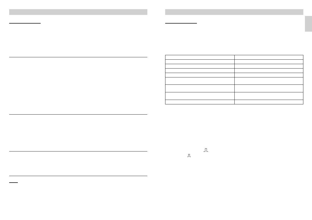
Examples of use Brightness settings
Night-time mode min
Corridors, foyers 1
Stairs, escalators, moving walkways 2
Washrooms, toilets, switchrooms, canteens 3
Sales fl oor, kindergartens, nursery school rooms,
sports halls
4
Work environments: Offi ces, conference and mee-
ting rooms, precision assembly activities, kitchens
5
Working areas requiring good light:
Laboratory, technical drawing, precision work
>=6
Daylight mode max
Stay-'ON' time for switching
output 1
Setting 30 sec. – 30 min.
The chosen stay-'ON' time is infi-
nitely variable from a minimum
of approx. 30 sec. to a maximum
of 30 min. Light is calibrated after
3 min. When the threshold is
exceeded, the sensor switches
'OFF' after the stay-'ON' time
expires.
Time setting
If the dial is set to (fully anti-
clockwise), the unit is in pulse
mode, i.e. the output is switched
'ON' for approx. 2 sec. (e.g. for stair-
well lighting timer). Afterwards,
the sensor does not respond to
movement for approx. 8 sec.
Day mode is the only mode possi-
ble here because of dazzle by light
from external sources.
Turned fully clockwise: The stay-
'ON' time is self-learning and ad-
justs dynamically to user behav-
iour. The optimum time cycle is
determined by means of a learning
algorithm.
The shortest time is 5 min.,
the longest 20 min.
Pulse mode (except DIM)
IQ mode
The chosen response threshold
can be infinitely varied from
approx. 10 – 1000 lux.
Control dial turned fully clockwise:
MAX daylight mode
Control dial turned fully anti-clock-
wise: MIN night-time operation
Depending on the site of installa-
tion, the setting may need to
be corrected by 1-2 marks on
the scale.
Twilight setting
Potentiometer
Potentiometer
COM 1 + COM 2
Note: Depending on the site of installation, the setting may need to be corrected by 1 – 2 marks on the scale.
DIP 4
In the 'ON'-'OFF' setting, the light
can be switched 'ON' and 'OFF'
manually at any time (except in
pulse mode: no manual 'OFF').
In the 'ON' setting, light can no
longer be switched 'OFF' manu-
ally. The stay-'ON' time starts
from the beginning again each
time the button is pressed.
'ON'/'ON'-'OFF' button
DIP 1
Functions – Settings by DIP switch
Test mode has priority over all
other settings on the presence
detector and serves the purpose
of checking for proper working
order as well for testing the de-
tection zone. Irrespective of am-
bient light level, the presence
detector activates the light to
stay 'ON' for approx. 8 sec. in re-
sponse to movement in the
room (blue LED flashes when
movement is detected). All user-
selected potentiometer settings
apply in normal mode. The pres-
ence detector can also be set by
means of the blue LED without
any load connected.
Normal mode / Test mode (NORM / TEST)
DIP 2
The light automatically switches
'ON' and 'OFF' in relation to
brightness when someone is
present. Light can be switched
'ON' and 'OFF manually at any
time. This temporarily interrupts
the automatic switching func-
tion. Irrespective of the settings
selected, light stays 'ON' for 4
hours after manually pressing
the button twice or switches
'OFF' after manually pressing the
button once. Pressing the but-
ton before the 4 hours elapse
returns the Presence Control IR
Quattro to the normal operating
mode.
Semi-automatic mode (MAN) / fully automatic mode (AUTO)
Fully automatic mode: (AUTO)
Semi-automatic mode: (MAN)
The light now only switches
'OFF' automatically. Light is
switched 'ON' manually. Light
must be requested using the
button and stays 'ON' for the
time set at the potentiometer.
(pressing twice switches 'ON' for
4 hours).
DIP 3
Tells the sensor how to interpret
the incoming signal. Assigning
external buttons/switches allows
you to operate the detector as a
semi-automatic unit and over-
ride it manually at any time.
Operation either by button
or switch
Several buttons possible
on one control input
Only use illuminated push-
button with neutral conductor
connected
Cable length between sensor
and switch < 50 m
Button/switch
COM 1 + COM 2
DIP 5
Provides a constant level of
brightness. Detector measures
the prevailing level of daylight
and activates sufficient artificial
light to achieve the required lev-
el of brightness. As daylight
changes, the switched-in artifi-
cial lighting component is ad-
justed accordingly. In addition to
the daylight component, artificial
light is also switched 'ON' and
'OFF' in relation to whether or
not persons are present.
Constant light 'ON'/'OFF'
DIM
GB
PC PRO HF360_DualHF_Zentraleuropa.indd 24-25PC PRO HF360_DualHF_Zentraleuropa.indd 24-25 11.09.13 10:3811.09.13 10:38
- 26 - - 27 -
The master/slave configuration
permits detection of movement in
large-type rooms or spaces (load
connected = master, no load =
slave). The level of brightness pre-
vailing in the room is only evaluat-
ed at the master. The slaves report
movements detected to the mas-
ter. Lighting or HVAC is switched
'ON' and 'OFF' by the master only.
Master/slave
A parallel-connected configuration
also permits the use of several
masters. In this case, each master
operates the lighting group in
accordance with the level of
brightness it measures. Delay
times and brightness thresholds
are selected at each master as re-
quired. The switched load is spread
among the individual masters.
Presence is still detected collec-
tively by all detectors. The pres-
ence output can be picked off
from any master.
Master/master
Remote control
Using the remote control (option-
al), functions can be conveniently
activated from the floor.
Note: The pulse mode cannot be
overridden by the remote control.
Switch pulse mode 'OFF' manually.
Presence Control remote control
unit: EAN no.: 4007841 000387
Parallel-connected configurations
Two detectors linked with an
external stairwell lighting
timer
Old building / building moderni-
sation
External light source activated by
button. No twilight mode, day
mode only.
Detector as stairwell lighting
timer
14.1
14.2
14.3
14.4
When using several detectors, they must be connected to the same phase!
DIM detector
14.5
Setting 1 sec. – 2 hr.
Turned fully clockwise: max
Turned fully anti-clockwise: min
Setting 0 sec. – 10 min.
Turned fully clockwise:
Room surveillance
Turned fully anti-clockwise:
0 sec. ('OFF')
Turning the potentiometer to the
"Surveillance" setting reduces the
sensitivity of the "Presence"
switching output. The contact only
closes on detecting a pronounced
movement, signalising with a high
degree of certainty that persons
are present.
The stay-'ON- time remains
active. The switch-'ON' delay
is inactivated.
Switch-'ON' delay for switching output 2 HVAC
Reach adjustment
COM 2
Potentiometer
Potentiometer
Provides basic illumination for the
selected stay-'ON' time when ambi-
ent light falls below the selected
brightness threshold that is set. This
can be dimmed to 10% of maxi-
mum light intensity. As soon as a
person enters the scene, the detec-
tor switches either to 100% light
intensity (constant-lighting control-
ler 'OFF') or adjusts to the preselect-
ed brightness level (constant-light-
ing controller 'ON'). When no move-
ment is being detected, the detec-
tor dims back to basic brightness
after the stay-'ON' time expires. This
is switched 'OFF' when stay-'ON'
time (1 min. – 30 min.) has expired
or the daylight component is suffi-
cient to exceed the selected level of
brightness. In the 'ON' setting, the
detector switches basic brightness
'ON' and 'OFF' as soon as the level
of light falls below the brightness
threshold.
Basic brightness (DIM option)
Potentiometer
Stay-'ON' time for switching output 2 HVAC
The reach required (response
threshold) is infinitely variable.
HF 360
1 m min. – 8 m max.
DUAL HF
min. 3 x 3 m – 10 x 3 m in
each direction
Turned fully anticlockwise
(factory setting) = minimum reach
Turned fully clockwise
(factory setting) = maximum reach
Potentiometer
GB
PC PRO HF360_DualHF_Zentraleuropa.indd 26-27PC PRO HF360_DualHF_Zentraleuropa.indd 26-27 11.09.13 10:3811.09.13 10:38
- 28 - - 29 -
Functional Warranty
Declaration of Conformity
This Steinel product has been
manufactured with utmost care,
tested for proper operation and
safety and then subjected to ran-
dom sample inspection. Steinel
guarantees that it is in perfect
condition and proper working
order.
The warranty period is 36 months
and starts on the date of sale to
the consumer. We will remedy
defects caused by material flaws
or manufacturing faults. The war-
ranty will be met by repair or re-
placement of the defective parts
at our own discretion. The war-
ranty shall not cover damage to
wear parts, damage or defects
caused by improper treatment or
maintenance. Further conse-
quential damage to other ob-
jects is excluded.
Claims under the warranty will
only be accepted if the product
is sent fully assembled and well
packed complete with a brief
description of the fault as well as
a receipt or invoice (date of pur-
chase and dealer's stamp) to the
appropriate Service Centre.
Repair service:
Please ask your nearest service
centre how to proceed for repair-
ing faults not covered by the
warranty or occurring after the
warranty expires.
Troubleshooting
Light does not switch 'ON'
Light does not switch 'OFF'
Sensor switches 'OFF' in spite of
persons being present
Sensor does not switch 'OFF'
quickly enough
Sensor does not switch 'ON'
quickly enough when approached
from the front
Sensor does not switch 'ON' when
persons are present in spite of it
being dark
No supply voltage
Lux setting too low
No motion detection
Lux setting too high
Stay-'ON' time running out
Interference from sources of
heat, e.g.: fan heater, open
doors and windows, pets,
light bulb/halogen floodlight,
moving objects
Stay-'ON' time too short
Light-level threshold too low
Stay-'ON' time too long
Reach is reduced when
approached from the front
Lux setting too low
Check supply voltage
Slowly increase lux setting
until light switches 'ON'
Ensure unobstructed sensor
vision
Check detection zone
Reduce lux setting
Wait until stay-'ON' time
elapses; reduce stay-'ON'
time if necessary
Use stickers to mask out
stationary sources of
interference
Increase stay-'ON' time
Change light threshold
Reduce stay-'ON' time
Install additional sensors
Reduce distance between
two sensors
Sensor deactivated by
switch/button?
Semi-automatic mode?
Increase light-level threshold
Malfunction Cause Remedy This product complies with
- Low Voltage Directive 2006/95/EC
- EMC Directive 2004/108/EC
- RoHS Directive 2011/65/EC
- WEEE Directive 2012/19/EC
GB
PC PRO HF360_DualHF_Zentraleuropa.indd 28-29PC PRO HF360_DualHF_Zentraleuropa.indd 28-29 11.09.13 10:3811.09.13 10:38
  • Page 1 1
  • Page 2 2
  • Page 3 3
  • Page 4 4
  • Page 5 5
  • Page 6 6
  • Page 7 7
  • Page 8 8
  • Page 9 9
  • Page 10 10
  • Page 11 11
  • Page 12 12
  • Page 13 13
  • Page 14 14
  • Page 15 15
  • Page 16 16
  • Page 17 17
  • Page 18 18
  • Page 19 19
  • Page 20 20
  • Page 21 21
  • Page 22 22
  • Page 23 23
  • Page 24 24
  • Page 25 25
  • Page 26 26
  • Page 27 27
  • Page 28 28
  • Page 29 29
  • Page 30 30
  • Page 31 31
  • Page 32 32
  • Page 33 33
  • Page 34 34
  • Page 35 35
  • Page 36 36
  • Page 37 37
  • Page 38 38
  • Page 39 39
  • Page 40 40
  • Page 41 41
  • Page 42 42
  • Page 43 43
  • Page 44 44
  • Page 45 45
  • Page 46 46
  • Page 47 47
  • Page 48 48
  • Page 49 49
  • Page 50 50
  • Page 51 51
  • Page 52 52
  • Page 53 53
  • Page 54 54
  • Page 55 55
  • Page 56 56
  • Page 57 57
  • Page 58 58
  • Page 59 59
  • Page 60 60
  • Page 61 61
  • Page 62 62
  • Page 63 63
  • Page 64 64
  • Page 65 65
  • Page 66 66
  • Page 67 67
  • Page 68 68
  • Page 69 69
  • Page 70 70
  • Page 71 71
  • Page 72 72
  • Page 73 73
  • Page 74 74
  • Page 75 75

STEINEL ST 2978 Owner's manual

Category
Motion detectors
Type
Owner's manual
This manual is also suitable for

Ask a question and I''ll find the answer in the document

Finding information in a document is now easier with AI