Broan 162 Installation guide

Category
Space heaters
Type
Installation guide

Broan 162 is a versatile ventilation solution that combines heating and exhaust fan capabilities in one compact unit. Ideal for bathrooms, it efficiently removes moisture and odors while providing supplemental heat. With its adjustable mounting brackets, the unit can be installed between joists for a secure and stable fit. The damper/duct connector allows for easy attachment of standard 4" round ductwork, ensuring effective air exhaust. The unit's dual functionality makes it a convenient choice for maintaining a comfortable and well-ventilated bathroom environment.

Broan 162 is a versatile ventilation solution that combines heating and exhaust fan capabilities in one compact unit. Ideal for bathrooms, it efficiently removes moisture and odors while providing supplemental heat. With its adjustable mounting brackets, the unit can be installed between joists for a secure and stable fit. The damper/duct connector allows for easy attachment of standard 4" round ductwork, ensuring effective air exhaust. The unit's dual functionality makes it a convenient choice for maintaining a comfortable and well-ventilated bathroom environment.

READ AND SAVE
THESE INSTRUCTIONS
MODELS 161 & 163 (TYPE IC) BULB
HEATERS
MODELS 162 (TYPE IC) & 164 (TYPE
IC) BULB HEATER/FANS
LEA Y CONSERVE
ESTAS INSTRUCCIONES
INSTALLER: Leave This Manual With The Homeowner. HOMEOWNER: Use and Care Information on Page 3.
INSTALADOR: Deje este manual con el dueño de casa. DUEÑO DE CASA: Información del uso y mantenimiento en la página 3.
CALENTADORES DE BOMBILLA
MODELOS 161 & 163 (TIPO IC)
CALENTADOR DE BOMBILLA\VENTILADORES
MODELOS 162 (TIPO IC) & 164 (TIPO)
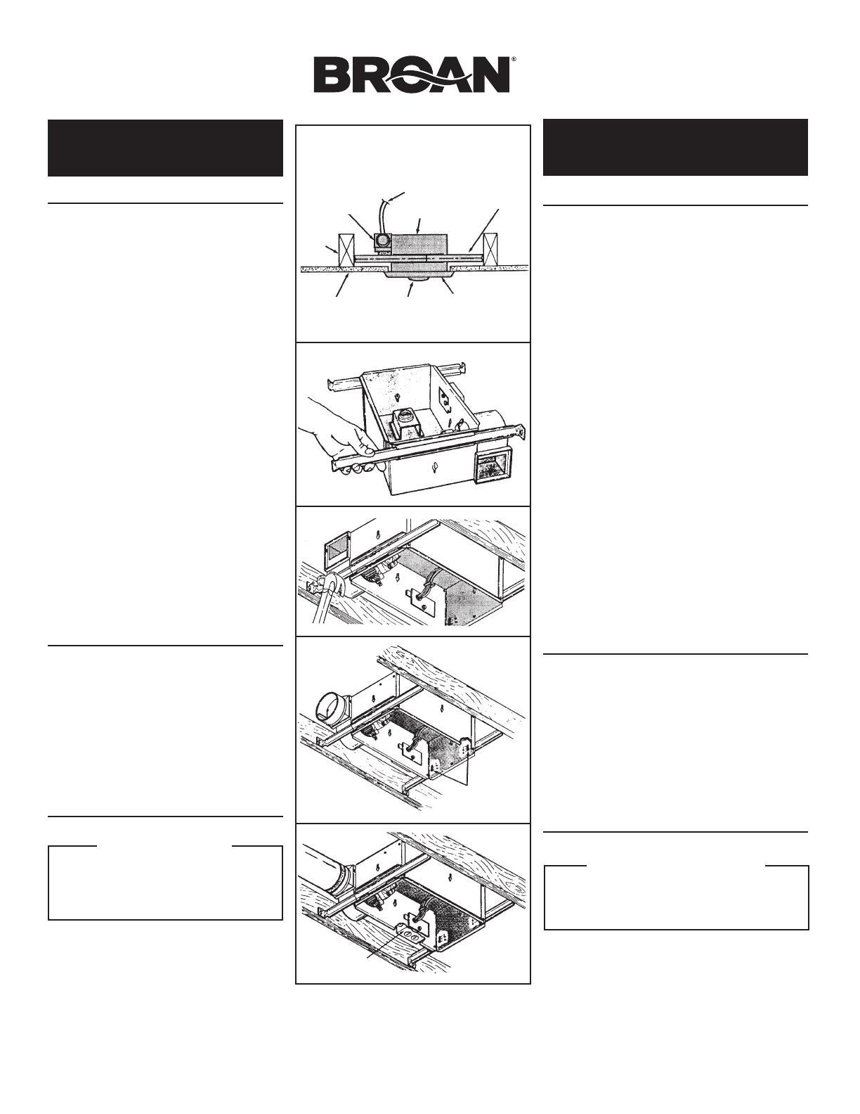
FIG. 1
CEILING MATE-
RIAL
MATERIAL DEL
CIELO RASO
GRILLE
REJILLA
DAMPER/DUCT CON-
NECTOR (162 & 164
ONLY)
AMORTIGUADOR/
ACOPLE DE CON-
DUCTO (162 Y 164
SOLAMENTE)
POWER
CABLE
CABLE DE
POTENCIA
HOUSING
CAJA
MOUNTING
BRACKET
SOPORTE DE
MONTAJE
CEILING
JOIST
VIGA DEL
CIELO
RASO
BULB(S)
BOMBILLA
FIG. 2
FIG. 3
FIG. 4
FIG. 5
VERTICAL ADJUSTING
SCREWS
TORNILLOS DE AJUSTE
VERTICAL
WIRING BOX
CAJA DE CONEXIONES
WARNING
TO REDUCE THE RISK OF FIRE, ELECTRICAL
SHOCK, OR INJURY TO PERSONS, OBSERVE THE
FOLLOWING:
1. Use this unit only in the manner intended by the
manufacturer. If you have questions, contact the
manufacturer at the address or telephone number
listed in the warranty.
2. Before servicing or cleaning unit, switch power off
at service panel and lock service panel to prevent
power from being switched on accidentally. When
the service disconnecting means cannot be locked,
securely fasten a prominent warning device, such
as a tag, to the service panel.
3. Installation work and electrical wiring must be done
by a qualified person(s) in accordance with all ap-
plicable codes and standards, including fire-rated
construction codes and standards.
4. Sufficient air is needed for proper combustion and
exhausting of gases through the flue (chimney) of
fuel burning equipment to prevent backdrafting. Fol-
low the heating equipment manufacturer's guideline
and safety standards such as those published by
the National Fire Protection Association (NFPA),
and the American Society for Heating, Refrigeration
and Air Conditioning Engineers (ASHRAE), and the
local code authorities.
5. When cutting or drilling into wall or ceiling, do not
damage electrical wiring and other hidden utilities.
6. Do not install this unit over a tub or shower.
7. NEVER place a switch where it can be reached
from a tub or shower.
8. Do not operate unit with dimmer switch or speed
control.
9. MODEL 161 ONLY: Install housing no closer than
6" from side wall. For supply connections, use wire
suitable for 75°C minimum. Do not install insulation
within 3 inches of top or sides of housing.
CAUTION
1. For general ventilating use only. Do not use to exhaust
hazardous or explosive materials and vapors.
2. This product is designed for installation in flat ceil-
ings only. DO NOT MOUNT THIS PRODUCT IN
A WALL.
3. To avoid motor bearing damage and noisy and/or
unbalanced impellers, keep drywall spray, construc-
tion dust, etc. off power unit.
4. Please read specification label on product for
further information and requirements.
PLAN THE
INSTALLATION
Choose the location for your heater. Refer to Warnings
and Cautions above.
MODELS 162 & 164 ONLY:
THE UNIT WILL OPERATE MOST EFFICIENTLY
WHEN LOCATED WHERE THE SHORTEST
POSSIBLE DUCT RUN AND MINIMUM NUMBER
OF ELBOWS WILL BE NEEDED. UNITS ARE
DESIGNED FOR USE WITH STANDARD 4"
ROUND DUCT.
Note that two-bulb units (163 & 164) can be fitted with
one infrared bulb (for heat) and one reflector bulb (for
light). Dual or multi-controls can be used for separate
control of bulbs and/or exhaust fan. Purchase controls
separately.
ADVERTENCIA
Para reducir el riesgo de incendio, descarga eléctrica o
lesiones personales, siga las siguientes instrucciones:
1. Solamente use esta unidad en la forma propuesta por el
fabricante. Si tiene alguna pregunta, póngase en contacto
con el fabricante en la dirección o número de teléfono que
aparece en la garantía.
2. Antes de limpiar o dar servicio a esta unidad, desconecte la
potencia en el panel de servicio y asegure éste para evitar
que resuma automáticamente. Cuando el dispositivo para
desconectar el servicio eléctrico no puede ser cerrado
con algún tipo de traba, sujete fuertemente al panel de
servicio, una etiqueta de advertencia prominente.
3. El trabajo de instalación y el cableado eléctrico deben
llevarse a cabo por personal competente, de conformidad
con todos los códigos y normas correspondientes,
incluyendo los códigos y normas de construcción contra
incendios.
4. Se requiere una cantidad de aire suficiente para una
correcta combustión y expulsión de gases por la
chimenea del equipo que quema combustible, para evitar
la retrogresión de la llama. Cumpla con las directrices y
las normas de seguridad del fabricante de equipos de
calefacción, tales como las publicadas por la Asociación
Nacional de Protección Contra Incendios (NFPA) y la
Asociación Norteamericana de Ingenieros de Calefacción,
Refrigeración y Aire Acondicionado (ASHRAE), y los
códigos de las autoridades locales.
5. Al cortar o perforar la pared o cielo raso, no dañe el
alambrado eléctrico ni otras instalaciones no visibles.
6. No instale la unidad encima de una bañera o ducha.
7. NUNCA coloque un interruptor en un lugar que pueda ser
alcanzado desde una bañera o ducha.
8. No haga funcionar esta unidad con un variador de luz o
control de velocidad.
9. SOLAMENTE MODELO 161: Instale la caja a no menos
de 16 cm de la pared lateral. Para conexiones de
alimentación, use un alambre apropiado para un mínimo
de 75
o
C. No instale el aislamiento dentro de los 8 cm del
tope o los costados de la caja.
CUIDADO
1. Solamente para uso de ventilación general. No lo use para
extraer materiales y vapores peligrosos o explosivos.
2. Este producto está diseñado solamente para instalarse
en los techos planos. NO MONTE ESTE PRODUCTO
EN LA PARED.
3. Para evitar daños al cojinete del motor e impulsores
ruidosos y/o desequilibrados, mantenga la unidad de
potencia lejos de rocíos de yeso, polvo de construcción,
etc.
4. Para más información y requisitos, lea la etiqueta de
especificación sobre el producto.
PLANIFICACION DE LA INS-
TALACION
Escoja un lugar para su calentador. Lea las instrucciones de
ADVERTENCIA” y “CUIDADO” que aparecen arriba.
MODELOS 162 & 164 SOLAMENTE:
LA UNIDAD FUNCIONARÁ EN FORMA MÁS EFICIENTE
SI SE UBICA EN UN LUGAR DONDE SE MINIMICE EL
TENDIDO DE CONDUCTOS Y EL NÚMERO DE CODOS.
LAS UNIDADES HAN SIDO DISEÑADAS PARA USO
CON CONDUCTO REDONDO ESTÁNDAR DE 10 cm.
Note que las unidades de dos bombillas (163 & 164) pueden
montarse con una bombilla infrarroja (para la calefacción) y
una bombilla reflectora (para la luz). Se pueden usar controles
dobles o múltiples para un control separado de las bombillas
y/o ventilador extractor de aire. Los controles se compran por
separado.
FIG. 6
WHITE to
WHITE / GRAY
BLANCO a
BLANCO / GRIS
120 VAC LINE IN
LINEA DE ENTRADA 120 VCA
GROUND
TIERRA
BLACK
NEGRO
BLACK
NEGRO
WHITE
to WHITE
BLANCO
to BLANCO
BLACK to
RED & BLUE
NEGRO a
ROJO y AZUL
GROUND
TIERRA
SWITCH OR TIMER
INTERRUPTOR O
TEMPORIZADOR
120 VAC LINE IN
LINEA DE ENTRADA 120 VCA
GROUND
TIERRA
BLACK
NEGRO
BLACK
NEGRO
WHITE to
WHITE
BLANCO a
BLANCO
WHITE to WHITE
BLANCO a BLANCO
GROUND
TIERRA
BLACK to
BLACK
NEGRO a
NEGRO
SWITCH OR TIMER
CONMUTADOR O
TEMPORIZADOR
MODEL / MODELO 161
MODEL / MODELO 162
Lamp & Vent operate together
La lámpara y el ventilador funcionan a la vez
2
Follow these basic steps when installing this unit:
(Fig. 1)
Nail unit to joists.
Attach ductwork (Models 162 or 164 only).
Connect power cable.
Fasten grille to housing.
PREPARE THE HEATER
1. Remove the unit from carton. Save carton for use
as plaster shield in rough-in installations.
2. Slide adjustable mounting brackets into bracket
channels on housing. (Fig. 2)
INSTALL THE HEATER
1. Position unit between joists and extend mounting
brackets.
2. Nail brackets firmly to joists. Bottom of brackets
should be positioned flush with joist bottom. (Fig. 3)
3. Brackets are factory-set for ½" thick ceiling mate-
rial. For thicker ceilings, loosen 4 vertical adjusting
screws and lower housing to appropriate thickness
on gauges. Tighten vertical adjusting screws firmly.
(Fig. 4)
ATTACH DUCTWORK
(MODELS 162 & 164 ONLY)
1. Snap the damper/duct connector onto housing.
Make sure that tabs on the connector lock in hous-
ing slots and that gravity closes damper. (Fig. 4)
2. Attach 4" round duct to damper/duct connector and
run ductwork to the outside through a roof or wall
cap. Check damper to make sure it opens freely.
Tape all joints to make them secure and air tight.
(Fig. 5)
WIRE THE HEATER
1. Remove wiring box from side of housing. Remove
knockout(s) and connect power cable(s) to wiring
box using proper U.L. approved connector.
2. Wire unit as indicated in appropriate diagram. (Fig.
6) Push all wiring into wiring box and replace wiring
box onto housing.
Al instalar esta unidad, siga los siguientes pasos básicos:
(Fig. 1)
Clave la unidad a las vigas.
Fije los conductos (modelos 162 o 164 solamente).
Conecte el cable de potencia.
Fije la rejilla a la caja.
PREPARACION DEL CALENTADOR
1. Saque la unidad de la caja de cartón. Guarde la caja de
cartón para su uso como escudo de yeso al principio
de una instalación.
2. Meta los soportes de montaje ajustables en los canales
de soporte en la caja. (Fig. 2)
I
NSTALACION DEL CALENTADOR
1. Coloque la unidad entre las vigas y extienda los soportes
de montaje.
2. Clave firmemente los soportes en las vigas. Las partes
de abajo de los soportes deben colocarse a nivel con
la parte de abajo de la viga. (Fig. 3)
3. Los soportes se fijan en fábrica para material de cielo
raso de un grosor de 1,3 cm. Para cielo raso más
gruesos, afloje 4 tornillos de ajuste vertical y baje la
caja al grosor apropiado según los calibradores. Atornille
firmemente los tornillos de ajuste vertical. (Fig. 4)
FIJE LOS CONDUCTOS
(MODELOS 162 & 164 SOLAMENTE)
1. Enganche el acople de amortiguador/conducto en
la caja. Compruebe que las orejetas en el acople
se enganchen en las ranuras de la caja y que el
amortiguador cierre por gravedad. (Fig. 4)
2. Fije el conducto redondo de 10 cm al acople del
amortiguador/conducto y saque el tendido de los
conductos al exterior a través de una cubierta de cielo
raso o pared. Verifique que el amortiguador se abra
libremente. Ponga cinta alrededor de todas las uniones
para que queden seguras y herméticas.(Fig. 5)
CABLEADO DEL CALENTADOR
1. Quite la caja de conexiones del costado de la caja.
Saque un disco(s) removible y conecte cable(s) de
potencia a la caja de conexiones usando el conector
correcto aprobado por U.L.
2. Haga el cableado de la unidad tal como se indica en
el diagrama correspondiente. (Fig. 6) Ponga todas las
conexiones en la caja de conexiones y vuelva a colocar
ésta en su lugar.
WHITE to
WHITE / GRAY
BLANCO a
BLANCO / GRIS
120 VAC LINE IN
LINEA DE ENTRADA 120 VCA
GROUND
TIERRA
BLACK
NEGRO
BLACK
NEGRO
WHITE to
WHITE
BLANCO a
BLANCO
BLACK to
BLACK
& RED
NEGRO a
NEGRO
y ROJO
GROUND
TIERRA
SWITCH OR TIMER
INTERRUPTOR O
TEMPORIZADOR
MODEL / MODELO 163
Lamps operate together
Las lámparas funcionan a la vez
RED
ROJO
VENT
EXTRACCION
WHITE to
WHITE / GRAY
BLANCO a
BLANCO / GRIS
120 VAC LINE IN
LINEA DE ENTRADA 120 VCA
BLACK
NEGRO
BLACK
NEGRO
WHITE to
WHITE
BLANCO a
BLANCO
BLACK TO BLUE
NEGRO A AZUL
RED TO RED
ROJO A ROJO
GROUND
TIERRA
HEAT
CALIFACCION
DUAL CONTROL
CONTROL DE DOS
FUNCCIONES
GROUND
TIERRA
MODEL / MODELO 162
Lamp & Vent operate separately
La lámpara y el ventilador funcionan por
separado
WHITE to
WHITE / GRAY
BLANCO a
BLANCO / GRIS
120 VAC LINE IN
LINEA DE ENTRADA 120 VCA
GROUND
TIERRA
BLACK
NEGRO
BLACK
NEGRO
LIGHT
LUZ
BLACK to BLACK
NEGRO a NEGRO
GROUND
TIERRA
HEAT
CALIFACCION
RED
ROJO
DUAL CONTROL
CONTROL DE DOS
FUNCCIONES
RED to RED
ROJO a ROJO
WHITE to
WHITE
BLANCO a
BLANCO
MODEL / MODELO 163
Lamps operate separately
Las lámparas funcionan por separado
FINAL ASSEMBLY
1. Protect motor, bulb sockets and wiring from con-
struction dust, drywall spray, paint, etc. by using
the plaster shield. Cut it from the carton and follow
directions printed on it. (Fig. 7)
2. Finish all ceiling work as necessary.
3. Remove plaster shield and check if bottom of
housing is flush with finished ceiling. If not, loosen
vertical adjusting screws, reposition housing, and
retighten screws.
4. Attach grille by hooking springs onto clips on side
of housing. (Fig. 8)
5. Install BR40 or R40-size 250W infrared bulb(s).
Center grille around bulb(s).
USE AND CARE
MODELS 162 & 164 OPERATION NOTE: These units
are designed with a thermostat which senses excess
heat and may start the blower automatically. This is
normal and is no cause for concern.
DISCONNECT ELECTRIC POWER SUPPLY AND
LOCK OUT SERVICE PANEL BEFORE CLEANING
OR SERVICING THIS UNIT.
To clean fan assembly: Remove bulb(s). Unhook
springs and remove grille. Loosen motor assembly
mounting screws and rotate assembly to remove it from
housing. Gently vacuum fan, motor and interior of hous-
ing. Reverse steps to replace fan assembly.
To clean grille assembly: Remove bulb(s). Unhook
springs and remove grille. Clean grille with mild soapy
water. Use a mild detergent, such as dishwashing liquid.
Dry with a soft cloth. DO NOT USE ABRASIVE CLOTHS,
STEEL WOOL PADS OR SCOURING POWDERS.
Motor is permanently lubricated — Do not oil or disas-
semble motor.
ENSAMBLADO FINAL
1. Proteja el motor, enchufe de la bombilla y cableado
contra el polvo de la construcción, rocíos de yeso,
pintura, etc., usando el escudo de yeso. Córtelo de la
caja de cartón y siga las instrucciones que aparecen
impresas en la misma. (Fig. 7)
2. Termine el trabajo de cielo raso ségun se necesite.
3. Quite el escudo de yeso y verifique si la parte inferior
de la caja está a nivel con el cielo raso terminado. De
lo contrario, afloje los tornillos de ajuste vertical, cambie
la posición de la caja y vuelva a apretar los tornillos.
4. Fije la rejilla enganchando los resortes a los sujetadores
al costado de la caja. (Fig. 8)
5. Instale bombilla(s) infrarrojas 250W de tamaño BR40
o R40. Centre la rejilla alrededor de la(s) bombilla(s).
USO Y MANTENIMIENTO
INSTRUCCIONES SOBRE EL FUNCIONAMIENTO DEL
MODELOS 162 Y 164: Estas unidads ha sido diseñada con
un termostato que detecta los excesos de calor y puede
encender el soplador automáticamente. Esto es normal y
no debe ser motivo de preocupación.
DESCONECTE EL SUMINISTRO DE ENERGIA ELEC-
TRICA Y ASEGURE EL PANEL DE SERVICIO ANTES DE
LIMPIAR O DAR SERVICIO A ESTA UNIDAD.
Para limpiar el equipo de ventilador: quite la(s) bombilla(s).
Desenganche los resortes y quite la rejilla. Afloje los torni-
llos de montaje del equipo del motor y gire el equipo para
sacarlo de la caja. Limpie por aspiración el ventilador, motor
e interior de la caja. Proceda al revés para reemplazar el
equipo del ventilador.
Para limpiar el equipo de la rejilla: quite la(s) bombilla(s).
Desenganche los resortes y saque la rejilla. Limpie la rejilla
con agua enjabonada. Use un detergente suave, como por
ejemplo líquido de lavado de platos. Seque con un paño
liviano. NO USE PAÑOS ÁSPEROS, LANA DE ACERO O
POLVOS DE FREGADO.
El motor está lubricado en forma permanente. No aceite ni
desarme el motor.
FIG. 6 (CONT')
3
MODEL / MODELO 164
Vent & Heat operate together -
Light separately
El Ventilador y Calentador funcionan a la vez
-La Luz por separado
MODEL / MODELO 164
Lamps operate together -
Vent separately
Las Lamparas funcionan a la vez -
El ventilador por separado
120 VAC LINE IN
LINEA DE ENTRADA 120 VCA
GROUND
TIERRA
LIGHT
LUZ
DUAL CONTROL
CONTROLE DE 2 FUNCCIONES
3 WHITE / GRAY WIRES
3 ALAMBRES
BLANCO / GRIS
VENT & HEAT
VENTILADOR y
CALEFACCION
BLACK to BLACK,
& YELLOW
NEGRO a
NEGRO
y AMARILLO
RED to RED
& BLUE
ROJO a ROJO
y AZUL
GROUND / TIERRA
RED
ROJO
WHITE to
WHITE
BLANCO a
BLANCO
BLACK
NEGRO
120 VAC LINE IN
LINEA DE ENTRADA 120 VCA
GROUND
TIERRA
VENT
VENTILADOR
DUAL CONTROL
CONTROLE DE 2 FUNCCIONES
3 WHITE / GRAY WIRES
3 ALAMBRES
BLANCO / GRIS
HEAT & LIGHT
CALEFACCION
y LUZ
BLACK to
BLUE
NEGRO a
AZUL
RED to RED,
BLACK &
YELLOW
ROJO a ROJO,
NEGRO y
AMARILLO
GROUND / TIERRA
RED
ROJO
WHITE to
WHITE
BLANCO a
BLANCO
BLACK
NEGRO
WIRE COLOR LEGEND
For wiring diagrams
on pages 2 & 3
WHITE
BLANCO
RED
ROJO
BLACK
NEGRO
BLUE
AZUL
GROUND
TIERRA
YELLOW
AMARILLO
120 VAC LINE IN
LINEA DE ENTRADA 120 VCA
GROUND
TIERRA
LIGHT
& VENT
LUZ y
EXTRACCION
DUAL CONTROL
CONTROLE DE 2 FUNCCIONES
3 WHITE / GRAY WIRES
3 ALAMBRES
BLANCO / GRIS
HEAT
CALEFACCION
BLACK to
BLACK, & BLUE
NEGRO a
NEGRO y AZUL
RED to RED
& YELLOW
ROJO a ROJO
y AMARILLO
GROUND / TIERRA
RED
ROJO
WHITE to
WHITE
BLANCO a
BLANCO
BLACK
NEGRO
MODEL / MODELO 164
Light & Vent operate together -
Heat separately
La luz y el ventilador funcionan a la vez -Calenta-
dor por separado
HEAT
CALIFACCION
120 VAC LINE IN
LINEA DE ENTRADA 120 VCA
GROUND
TIERRA
3 BLACK WIRES
3 ALAMBRES NEGR OS
3 WHITE WIRES
3 ALAMBRES
BLANCOS
LIGHT
LUZ
BLACK
NEGRO
3-FUNCTION CONTROL
CONTROL DE TRES FUNCCIONES
WHITE to WHITE / GRAY
BLANCO a BLANCO / GRIS
VENT
EXTRACCION
BLACK to BLACK
NEGRO a NEGRO
BLACK to YELLOW
NEGRO a AMAR ILLO
RED to RED
ROJ O a ROJO
RED / ROJO
GROUND / TIERRA
WHITE to WHITE
BLANCO a BLANCO
RED to BLUE
ROJ O a AZUL
MODEL / MODELO 164
Light, Vent & Heat operate separately
La luz, ventilador y calentador funcionan por
separado
FIG. 7
FIG. 8
99042412P
MODELS 163 & 164
MODELOS 163 & 164
KEY NO.
NO. CODIGO
1
2
3
4
5
6
7
8
9
10
11
12
13
14
15
16
17
19
20
21
22
23
24
25
**
MODEL 161
MODELO 161
97010319
06170-00
- - - -
- - - -
99770034
- - - -
- - - -
- - - -
99150545
99150546
- - - -
- - - -
97009475
- - - -
25067-00
99400026
99270830
- - - -
- - - -
98003036
98007763
25064-00
99150564
- - - -
- - - -
MODEL 162
MODELO 162
97010319
06170-00
97010254
98007352
99770034
- - - -
99260423
99160360
99150545
99150546
97010255
- - - -
97009476
97009595
20050-09
99400026
99270830
99270835
99270832
98003036
98007763
25064-00
99150564
99271191
- - - -
MODEL 163
MODELO 163
97010320
06170-00
97009724
98007426
99770034
99770037
99260423
99160360
99150545
99150546
- - - -
97009762
97009477
- - - -
20050-09
99400026
99270830
99270835
- - - -
98003036
98007763
25064-00
99150564
99271191
99270668
MODEL 164
MODELO 164
97010320
06170-00
97010254
98007352
99770034
99770037
99260423
99160360
99150545
99150546
97010255
- - - -
97009478
97009595
20050-09
99400026
99270830
99270835
99270832
98003036
98007763
25064-00
99150564
99271191
99270668
DESCRIPTION
Grille Assembly (Includes Key No. 2)
Grille Spring (2 Req.)
Motor
Motor Mounting Bracket
Bulb Holder
Bulb Holder
Nut, #8-32 (2 Req.)*
Screw, #8-32 x 1/2 (2 Req.)*
Sheet Metal Screw #8-18 x 3/8 (5 Req.)
(7 Req. -161)*
Ground Screw #8-18 x 3/8
Blower Wheel
Fan Blade
Housing (Includes Key Nos. 9 & 23)
Damper/Duct Connector
Wiring Box Cover
Bushing (2 Req. -163 & 164)
Wire Clip
Receptacle
Thermostat (Fan)
Mounting Bracket (4 Req.)
Bracket Channel (2 Req.)
Wiring Box
Screw, #8-18 x ½*
Thermostat (Lamps)
Crimp Connector (2 Req. -163)
(3 Req. -164)
Broan-NuTone LLC Hartford, Wisconsin www.broan.com 800-558-1711
* Standard Hardware. May be purchased locally * Equipo estándar. Se puede adquirir a nivel local.
** Not Shown ** No se muestra
Order service parts by "PART NO." - NOT by "KEY NO." Encargue piezas de servicio por "NO. PIEZ" - NO por "NO. CODIGO"
MODELS 161 & 162
MODELOS 161 & 162
PIEZAS DE SERVICIO
DESCRIPCION
Equipo de la rejilla (incluye clave No. 2)
Resorte de la rejilla (se requieren 2)
Motor
Soporte del montaje del motor
Portabombilla
Portabombilla
Tuerca, #8-32 (se requieren 2)*
Tornillo, #8-32 x 1/2 (se requieren 2)*
Tornillo de chapa metálica #8-18x3/8
(se req. 5)(se req. 7-161)*
Tornillo de tierra #8-18x3/8
Rueda del soplador
Paleta del ventilador
Casa (incluye claves No. 9 y 23)
Conector de amortiguador /conducto
Cubierta de caja de conexiones
Manguito aislador (se req. 2 - 163 y 164)
Sujetador de alambre
Enchufe
Termostato (Ventilador)
Soporte de montaje (se requieren 4)
Canal de soporte (se requieren 2)
Caja de conexiones
Tornillo, #8-18 x ½*
Termostato (Focos)
Conector de pliegue (se requieren 2 -163)
(se requieren 3 -164)
25
25
17
17
SERVICE PARTS
3
BROAN-NUTONE ONE YEAR LIMITED WARRANTY
Broan-NuTone warrants to the original consumer purchaser of its products that such products will be free from
defects in materials or workmanship for a period of one year from the date of original purchase. THERE ARE NO
OTHER WARRANTIES, EXPRESS OR IMPLIED, INCLUDING, BUT NOT LIMITED TO, IMPLIED WARRANTIES OF
MERCHANTABILITY OR FITNESS FOR A PARTICULAR PURPOSE.
During this one-year period, Broan-NuTone will, at its option, repair or replace, without charge, any product or part
which is found to be defective under normal use and service.
THIS WARRANTY DOES NOT EXTEND TO FLUORESCENT LAMP STARTERS, TUBES, HALOGEN AND INCANDESCENT
BULBS, FUSES, FILTERS, DUCTS, ROOF CAPS, WALL CAPS AND OTHER ACCESSORIES FOR DUCTING. This warranty
does not cover (a) normal maintenance and service or (b) any products or parts which have been subject to misuse,
negligence, accident, improper maintenance or repair (other than by Broan-NuTone), faulty installation or installation
contrary to recommended installation instructions.
The duration of any implied warranty is limited to the one-year period as specified for the express warranty. Some states
do not allow limitation on how long an implied warranty lasts, so the above limitation may not apply to you.
BROAN-NUTONE’S OBLIGATION TO REPAIR OR REPLACE, AT BROAN-NUTONE’S OPTION, SHALL BE THE
PURCHASER’S SOLE AND EXCLUSIVE REMEDY UNDER THIS WARRANTY. BROAN-NUTONE SHALL NOT BE LIABLE
FOR INCIDENTAL, CONSEQUENTIAL OR SPECIAL DAMAGES ARISING OUT OF OR IN CONNECTION WITH PRODUCT
USE OR PERFORMANCE. Some states do not allow the exclusion or limitation of incidental or consequential damages,
so the above limitation or exclusion may not apply to you.
This warranty gives you specific legal rights, and you may also have other rights, which vary from state to state. This
warranty supersedes all prior warranties.
To qualify for warranty service, you must (a) notify Broan-NuTone at the address or telephone number below, (b) give
the model number and part identification and (c) describe the nature of any defect in the product or part. At the time of
requesting warranty service, you must present evidence of the original purchase date.
Broan-NuTone LLC, 926 W. State Street, Hartford, Wisconsin 53027 www.broan.com 800-558-1711
GARANTÍA BROAN-NUTONE LIMITADA POR UN AÑO
Broan-NuTone garantiza al consumidor comprador original de sus productos que dichos productos carecerán de defectos en
materiales o en mano de obra por un período de un año a partir de la fecha original de compra. NO EXISTEN OTRAS GARANTÍAS,
EXPLICITAS O IMPLÍCITAS, INCLUYENDO, ENTRE OTRAS, GARANTÍAS IMPLÍCITAS DE COMERCIALIZACIÓN O APTITUD
PARA UN PROPÓSITO PARTICULAR.
Durante el período de un año, y a su propio criterio, Broan-NuTone reparará o reemplazará, sin costo alguno, cualquier producto
o pieza que se encuentre defectuosa bajo condiciones normales de servicio y uso.
LA PRESENTE GARANTÍA NO CUBRE LOS TUBOS FLUORESCENTES NI SUS ARRANCADORES, BOMBILLAS DE HALÓGENO
E INCANDESCENTES, FUSIBLES, FILTROS, CONDUCTOS, TAPONES DE TECHO O PAREDES Y DEMÁS ACCESORIOS PARA
CONDUCTOS. Esta garantía no cubre (a) mantenimiento y servicio normales o (b) cualesquiera productos o piezas que hayan
sido utilizados de forma errónea, negligente, que hayan causado un accidente, o que hayan sido reparados o mantenidos
inapropiadamente (por otras compañías que no sean Broan-NuTone), instalación defectuosa, o instalación contraria a las
instrucciones de instalación recomendadas.
La duración de cualquier garantía implícita se limita a un período de un año como se especifica en la garantía expresa. Algunos
estados no permiten limitaciones en cuanto al tiempo de vencimiento de una garantía implícita, por lo que la limitación antes
mencionada puede no aplicarse a usted.
LA OBLIGACIÓN DE BROAN-NUTONE DE REPARAR O REEMPLAZAR, SIGUIENDO EL CRITERIO DE BROAN-NUTONE, DEBERÁ
SER EL ÚNICO Y EXCLUSIVO RECURSO LEGAL DEL COMPRADOR BAJO ESTA GARANTÍA. BROAN-NUTONE NO SERÁ
RESPONSABLE POR DAÑOS INCIDENTALES, CONSECUENTES, O POR DAÑOS ESPECIALES QUE SURJAN A RAÍZ DEL USO O
DESEMPEÑO DEL PRODUCTO. Algunos estados no permiten la exclusión o limitación de daños incidentales o consecuentes,
por lo que la limitación antes mencionada puede no aplicarse a usted.
Esta garantía le proporciona derechos legales específicos, y usted puede también tener otros derechos, los cuales varían de
estado a estado. Esta garantía reemplaza todas las garantías anteriores.
Para calificar para la garantía de servicio, usted debe (a) notificar a Broan-NuTone al domicilio o al número de teléfono que se
menciona abajo, (b) dar el número del modelo y la identificación de la pieza, y (c) describir la naturaleza de cualquier defecto
en el producto o la pieza. En el momento de solicitar servicio cubierto por la garantía, usted debe de presentar un comprobante
con la fecha original de compra.
Broan-NuTone LLC, 926 W. State Street, Hartford, Wisconsin 53027 www.broan.com 800-558-1711
  • Page 1 1
  • Page 2 2
  • Page 3 3
  • Page 4 4

Broan 162 Installation guide

Category
Space heaters
Type
Installation guide

Broan 162 is a versatile ventilation solution that combines heating and exhaust fan capabilities in one compact unit. Ideal for bathrooms, it efficiently removes moisture and odors while providing supplemental heat. With its adjustable mounting brackets, the unit can be installed between joists for a secure and stable fit. The damper/duct connector allows for easy attachment of standard 4" round ductwork, ensuring effective air exhaust. The unit's dual functionality makes it a convenient choice for maintaining a comfortable and well-ventilated bathroom environment.

Ask a question and I''ll find the answer in the document

Finding information in a document is now easier with AI

in other languages