ASROCK H61 Pro Quick start guide
- Category
- Motherboards
- Type
- Quick start guide

1
ASRock H61 Pro Motherboard
English
Copyright Notice:
No part of this installation guide may be reproduced, transcribed, transmitted, or trans-
lated in any language, in any form or by any means, except duplication of documentation
by the purchaser for backup purpose, without written consent of ASRock Inc.
Products and corporate names appearing in this guide may or may not be registered
trademarks or copyrights of their respective companies, and are used only for identica-
tion or explanation and to the owners’ benet, without intent to infringe.
Disclaimer:
Specications and information contained in this guide are furnished for informational use
only and subject to change without notice, and should not be constructed as a commit-
ment by ASRock. ASRock assumes no responsibility for any errors or omissions that may
appear in this guide.
With respect to the contents of this guide, ASRock does not provide warranty of any kind,
either expressed or implied, including but not limited to the implied warranties or condi-
tions of merchantability or tness for a particular purpose. In no event shall ASRock, its
directors, ofcers, employees, or agents be liable for any indirect, special, incidental, or
consequential damages (including damages for loss of prots, loss of business, loss of
data, interruption of business and the like), even if ASRock has been advised of the pos-
sibility of such damages arising from any defect or error in the guide or product.
This device complies with Part 15 of the FCC Rules. Operation is subject to the following
two conditions:
(1) this device may not cause harmful interference, and
(2) this device must accept any interference received, including interference that
may cause undesired operation.
CALIFORNIA, USA ONLY
The Lithium battery adopted on this motherboard contains Perchlorate, a toxic substance
controlled in Perchlorate Best Management Practices (BMP) regulations passed by the
California Legislature. When you discard the Lithium battery in California, USA, please
follow the related regulations in advance.
“Perchlorate Material-special handling may apply, see
www.dtsc.ca.gov/hazardouswaste/perchlorate”
ASRock Website: http://www.asrock.com
Published August 2012
Copyright
©
2012 ASRock INC. All rights reserved.

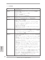
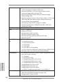
2
ASRock H61 Pro Motherboard
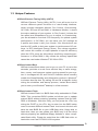
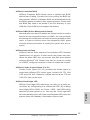
Motherboard Layout
English
1 1155-Pin CPU Socket 15 SATA2 Connector (SATA2_1, Blue)
2 CPU Fan Connector (CPU_FAN1) 16 System Panel Header (PANEL1, White)
3 ATX 12V Power Connector (ATX12V1) 17 USB 2.0 Header (USB8_9, Blue)
4 2 x 240-pin DDR3 DIMM Slots 18 USB 2.0 Header (USB6_7, Blue)
(Dual Channel: DDR3_A1, DDR3_B1, Blue) 19 COM Port Header (COM1)
5 ATX Power Connector (ATXPWR1) 20 Front Panel Audio Header
6 Chassis Fan Connector (CHA_FAN1) (HD_AUDIO1, White)
7 32Mb SPI Flash 21 PCI Express 2.0 x1 Slot (PCIE6, White)
8 Intel H61 Chipset 22 PCI Express 2.0 x1 Slot (PCIE5, White)
9 Clear CMOS Jumper (CLRCMOS1) 23 PCI Express 2.0 x1 Slot (PCIE4, White)
10 Chassis Speaker Header (SPEAKER 1, White) 24 PCI Express 2.0 x1 Slot (PCIE3, White)
11 SATA2 Connector (SATA2_2, Blue) 25 PCI Express 2.0 x16 Slot (PCIE2, Blue)
12 SATA2 Connector (SATA2_0, Blue) 26 PCI Express 2.0 x1 Slot (PCIE1, White)
13 Infrared Module Header (IR1) 27 Power Fan Connector (PWR_FAN1)
14 SATA2 Connector (SATA2_3, Blue)
ATXPWR1
Intel
H61
PCI Express 2.0
CMOS
Battery
32Mb
BIOS
DDR3_A1 (64 bi t, 240-pi n module)
DDR3_B1 (64 bi t, 240-pin module)
Super
I/O
LAN
PHY
AUD IO
COD EC
1
HD_ AUD IO1
COM1
1
USB6 _7
1
USB8 _9
1
1
SPEA KER1
HDLED RES ET
PLED P W RBTN
PANEL1
1
CLR CMOS 1
1
SATA2_ 1
SATA2_ 3
SATA2_ 0
SATA2_ 2
P CIE2
P CIE1
P CIE3
P CIE4
P CIE5
P CIE6
Dual Channel
Designed in Taipei
HDMI 1.4a
RoHS
ErP/EuP Ready
17.3cm (6.8 in)
30.5cm (12.0 in)
DX10.1
DDR3
H61 Pro
ATX1 2V1
IR1
1
PS2
Keyboard
PS2
Mouse
VGA1
Top:
RJ-45
USB 2 .0
T: US B4
B: USB 5
USB 2 .0
T: U SB 0
B: US B1
Top:
LIN E IN
Cen ter :
FRO NT
Bot tom :
MIC I N
USB 2 .0
T: U SB 2
B: US B3
HDMI1
CPU_ FAN1
CHA_ FAN1
PWR_ FAN1
1
2
3
4
5
6
7
8
9
10
11
12
14
13
15
16
17
18
1920
21
22
23
24
25
26
27

3
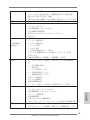
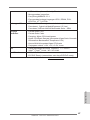
ASRock H61 Pro Motherboard
English
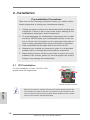
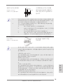
I/O Panel
* There are two LED next to the LAN port. Please refer to the table below for the LAN port LED
indications.
LAN Port LED Indications
Activity/Link LED SPEED LED
Status Description Status Description
Off No Link Off 10Mbps connection
Blinking Data Activity Orange 100Mbps connection
On Link Green 1Gbps connection
ACT/LINK
LED
SPEED
LED
LAN Port
1 PS/2 Mouse Port (Green) 7 USB 2.0 Ports (USB23)
* 2 LAN RJ-45 Port 8 USB 2.0 Ports (USB01)
3 Line In (Light Blue) 9 VGA/HDMI Port
** 4 Front Speaker (Lime) 10 VGA/D-Sub Port
5 Microphone (Pink) 11 PS/2 Keyboard Port (Purple)
6 USB 2.0 Ports (USB45)
1
2
5
3
6
7
8
9
11
4
10
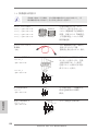
To enable Multi-Streaming function, you need to connect a front panel audio cable to the front
panel audio header. After restarting your computer, you will nd “VIA HD Audio Deck” tool on
your system. Please follow below instructions according to the OS you install.
For Windows
®
XP / XP 64-bit OS:
Please click “VIA HD Audio Deck” icon , and click “Speaker”. Then you are allowed to
select “2 Channel” or “4 Channel”. Click “Power” to save your change.
For Windows
®
7 / 7 64-bit / Vista
TM
/ Vista
TM
64-bit OS:
Please click “VIA HD Audio Deck” icon , and click “Advanced Options” on the left side
on the bottom. In “Advanced Options” screen, select “Independent Headphone”, and click
“OK” to save your change.

4
ASRock H61 Pro Motherboard
English
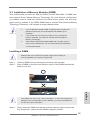
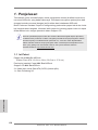
1. Introduction
Thank you for purchasing ASRock H61 Pro motherboard, a reliable motherboard
produced under ASRock’s consistently stringent quality control. It delivers excellent
performance with robust design conforming to ASRock’s commitment to quality and
endurance.
This Quick Installation Guide contains introduction of the motherboard and step-by-
step installation guide. More detailed information of the motherboard can be found
in the user manual presented in the Support CD.
Because the motherboard specications and the BIOS software might be
updated, the content of this manual will be subject to change without no-
tice. In case any modications of this manual occur, the updated version
will be available on ASRock website without further notice. You may nd
the latest VGA cards and CPU support lists on ASRock website as well.
ASRock website http://www.asrock.com
If you require technical support related to this motherboard, please visit
our website for specic information about the model you are using.
www.asrock.com/support/index.asp
1.1 Package Contents
ASRock H61 Pro Motherboard
(ATX Form Factor: 12.0-in x 6.8-in, 30.5 cm x 17.3 cm)
ASRock H61 Pro Quick Installation Guide
ASRock H61 Pro Support CD
2 x Serial ATA (SATA) Data Cables (Optional)
1 x I/O Panel Shield
ASRock Reminds You...
To get better performance in Windows
®
7 / 7 64-bit / Vista
TM
/ Vista
TM
64-
bit, it is recommended to set the BIOS option in Storage Conguration to
AHCI mode. For the BIOS setup, please refer to the “User Manual” in our
support CD for details.

5
ASRock H61 Pro Motherboard
English
1.2 Specications
Platform - ATX Form Factor: 12.0-in x 6.8-in, 30.5 cm x 17.3 cm
- All Solid Capacitor design
CPU - Supports 3
rd
and 2
nd
Generation Intel
®
Core
TM
i7 / i5 / i3 in
LGA1155 Package
- Supports Intel
®
Turbo Boost 2.0 Technology
- Supports K-Series unlocked CPU
Chipset - Intel
®
H61
- Supports Intel
®
Rapid Start Technology and Smart Connect
Technology
Memory - Dual Channel DDR3 Memory Technology
- 2 x DDR3 DIMM slots
- Supports DDR3 1600/1333/1066 non-ECC, un-buffered
memory (DDR3 1600 with Intel
®
Ivy Bridge CPU, DDR3
1333 with Intel
®
Sandy Bridge CPU)
- Max. capacity of system memory: 16GB (see CAUTION 1)
- Supports Intel
®
Extreme Memory Prole (XMP) 1.3 / 1.2 with
Intel
®
Ivy Bridge CPU
Expansion Slot - 1 x PCI Express 3.0 x16 slot (blue @ x16 mode)
* PCIE 3.0 is only supported with Intel
®
Ivy Bridge CPU. With
Intel
®
Sandy Bridge CPU, it only supports PCIE 2.0.
- 5 x PCI Express 2.0 x1 slots
Graphics * Intel
®
HD Graphics Built-in Visuals and the VGA outputs
can be supported only with processors which are GPU
integrated.
- Supports Intel
®
HD Graphics Built-in Visuals: Intel
®
Quick
Sync Video 2.0, Intel
®
InTru
TM
3D, Intel
®
Clear Video HD
Technology, Intel
®
Insider
TM
, Intel
®
HD Graphics 2500/4000
with Intel
®
Ivy Bridge CPU
- Supports Intel
®
HD Graphics Built-in Visuals: Intel
®
Quick
Sync Video, Intel
®
InTru
TM
3D, Intel
®
Clear Video HD
Technology, Intel
®
HD Graphics 2000/3000, Intel
®
Advanced
Vector Extensions (AVX) with Intel
®
Sandy Bridge CPU
- Pixel Shader 5.0, DirectX 11 with Intel
®
Ivy Bridge CPU.
Pixel Shader 4.1, DirectX 10.1 with Intel
®
Sandy Bridge
CPU.
- Max. shared memory 1760MB with Intel
®
Ivy Bridge CPU.
Max. shared memory 1759MB with Intel
®
Sandy Bridge
CPU.

6
ASRock H61 Pro Motherboard
English
- Dual VGA Output: support HDMI and D-Sub ports by
independent display controllers
- Supports HDMI 1.4a Technology with max. resolution up to
1920x1200 @ 60Hz
- Supports D-Sub with max. resolution up to 2048x1536 @
75Hz
- Supports Auto Lip Sync, Deep Color (12bpc), xvYCC and
HBR (High Bit Rate Audio) with HDMI
(Compliant HDMI monitor is required) (see CAUTION 2)
- Supports HDCP function with HDMI port
- Supports Full HD 1080p Blu-ray (BD) / HD-DVD playback
with HDMI port
Audio - 5.1 CH HD Audio (VIA
®
VT1705 Audio Codec)
LAN - PCIE x1 Gigabit LAN 10/100/1000 Mb/s
- Realtek RTL8111E
- Supports Wake-On-LAN
- Supports LAN Cable Detection
- Supports Energy Efcient Ethernet 802.3az
- Supports PXE
Rear Panel I/O I/O Panel
- 1 x PS/2 Mouse Port
- 1 x PS/2 Keyboard Port
- 1 x D-Sub Port
- 1 x HDMI Port
- 6 x Ready-to-Use USB 2.0 Ports
- 1 x RJ-45 LAN Port with LED (ACT/LINK LED and SPEED
LED)
- HD Audio Jack: Line in/Front Speaker/Microphone
Connector - 4 x SATA2 3.0 Gb/s connectors, support NCQ, AHCI and
Hot Plug functions
- 1 x IR header
- 1 x COM port header
- 1 x CPU Fan connector (4-pin)
- 1 x Chassis Fan connector (4-pin)
- 1 x Power Fan connector (4-pin)
- 24 pin ATX power connector
- 8 pin 12V power connector
- Front panel audio connector
- 2 x USB 2.0 headers (support 4 USB 2.0 ports)
BIOS Feature - 32Mb AMI UEFI Legal BIOS with GUI support
- Supports “Plug and Play”

7
ASRock H61 Pro Motherboard
English
- ACPI 1.1 Compliance Wake Up Events
- Supports jumperfree
- SMBIOS 2.3.1 Support
- IGPU, DRAM, PCH, CPU PLL, VTT, VCCSA Voltage
Multi-adjustment
Support CD - Drivers, Utilities, AntiVirus Software (Trial Version),
CyberLink MediaEspresso 6.5 Trial, ASRock MAGIX
Multimedia Suite - OEM
Hardware - CPU Temperature Sensing
Monitor - Chassis Temperature Sensing
- CPU/Chassis/Power Fan Tachometer
- CPU/Chassis Quiet Fan (Allow Chassis Fan Speed
Auto-Adjust by CPU Temperature)
- CPU/Chassis Fan Multi-Speed Control
- Voltage Monitoring: +12V, +5V, +3.3V, CPU Vcore
OS - Microsoft
®
Windows
®
7 / 7 64-bit / Vista
TM
/ Vista
TM
64-bit
/ XP / XP 64-bit compliant
Certications - FCC, CE, WHQL
- ErP/EuP Ready (ErP/EuP ready power supply is required)
* For detailed product information, please visit our website: http://www.asrock.com
WARNING
Please realize that there is a certain risk involved with overclocking,
including adjusting the setting in the BIOS, applying Untied Overclocking
Technology, or using third-party overclocking tools. Overclocking may
affect your system’s stability, or even cause damage to the components
and devices of your system. It should be done at your own risk and
expense. We are not responsible for possible damage caused by
overclocking.

8
ASRock H61 Pro Motherboard
English
CAUTION!
1. Due to the operating system limitation, the actual memory size
may be less than 4GB for the reservation for system usage
under Windows
®
7 / Vista
TM
/ XP. For Windows
®
OS with 64-bit
CPU, there is no such limitation. You can use ASRock XFast
RAM to utilize the memory that Windows
®
cannot use.
2. xvYCC and Deep Color are only supported under Windows
®
7
64-bit / 7. Deep Color mode will be enabled only if the display
supports 12bpc in EDID. HBR is supported under Windows
®
7
64-bit / 7 / Vista
TM
64-bit / Vista
TM
.

9
ASRock H61 Pro Motherboard
English
1.3 Unique Features
ASRock Extreme Tuning Utility (AXTU)
ASRock Extreme Tuning Utility (AXTU) is an all-in-one tool to
ne-tune different system functions in a user-friendly interface,
which includes Hardware Monitor, Fan Control, Overclocking,
OC DNA, IES and XFast RAM. In Hardware Monitor, it shows
the major readings of your system. In Fan Control, it shows the
fan speed and temperature for you to adjust. In Overclocking,
you are allowed to overclock CPU frequency for optimal system
performance. In OC DNA, you can save your OC settings as
a prole and share it with your friends. Your friends then can
load the OC prole to their own system to get the same OC set-
tings. In IES (Intelligent Energy Saver), the voltage regulator
can reduce the number of output phases to improve efciency
when the CPU cores are idle without sacricing computing per-
formance. In XFast RAM, it fully utilizes the memory space that
cannot be used under Windows
®
OS 32-bit CPU.
ASRock Instant Boot
ASRock Instant Boot allows you to turn on your PC in just a few
seconds, provides a much more efcient way to save energy,
time, money, and improves system running speed for your sys-
tem. It leverages the S3 and S4 ACPI features which normally
enable the Sleep/Standby and Hibernation modes in Windows
®
to shorten boot up time. By calling S3 and S4 at specic timing
during the shutdown and startup process, Instant Boot allows
you to enter your Windows
®
desktop in a few seconds.
ASRock Instant Flash
ASRock Instant Flash is a BIOS ash utility embedded in Flash
ROM. This convenient BIOS update tool allows you to update
system BIOS without entering operating systems rst like MS-
DOS or Windows
®
. With this utility, you can press the <F6> key
during the POST or the <F2> key to enter into the BIOS setup
menu to access ASRock Instant Flash. Just launch this tool and
save the new BIOS le to your USB ash drive, oppy disk or
hard drive, then you can update your BIOS only in a few clicks
without preparing an additional oppy diskette or other compli-
cated ash utility. Please be noted that the USB ash drive or
hard drive must use FAT32/16/12 le system.

10
ASRock H61 Pro Motherboard
English
ASRock APP Charger
If you desire a faster, less restricted way of charging your
Apple devices, such as iPhone/iPad/iPod Touch, ASRock has
prepared a wonderful solution for you - ASRock APP Charger.
Simply install the APP Charger driver, it makes your iPhone
charge much quickly from your computer and up to 40% faster
than before. ASRock APP Charger allows you to quickly charge
many Apple devices simultaneously and even supports continu-
ous charging when your PC enters into Standby mode (S1),
Suspend to RAM (S3), hibernation mode (S4) or power off (S5).
With APP Charger driver installed, you can easily enjoy the mar-
velous charging experience.
ASRock XFast USB
ASRock XFast USB can boost USB storage device perfor-
mance. The performance may depend on the properties of the
device.
ASRock XFast LAN
ASRock XFast LAN provides a faster internet access, which
includes the benefits listed below. LAN Application Prioritiza-
tion: You can congure your application’s priority ideally and/or
add new programs. Lower Latency in Game: After setting online
game’s priority higher, it can lower the latency in games. Trafc
Shaping: You can watch Youtube HD videos and download si-
multaneously. Real-Time Analysis of Your Data: With the status
window, you can easily recognize which data streams you are
transferring currently.
ASRock XFast RAM
ASRock XFast RAM is a new function that is included into AS-
Rock Extreme Tuning Utility (AXTU). It fully utilizes the memory
space that cannot be used under Windows
®
OS 32-bit CPU.
ASRock XFast RAM shortens the loading time of previously
visited websites, making web surfing faster than ever. And it
also boosts the speed of Adobe Photoshop 5 times faster. An-
other advantage of ASRock XFast RAM is that it reduces the
frequency of accessing your SSDs or HDDs in order to extend
their lifespan.

11
ASRock H61 Pro Motherboard
English
ASRock Crashless BIOS
ASRock Crashless BIOS allows users to update their BIOS
without fear of failing. If power loss occurs during the BIOS up-
date process, ASRock Crashless BIOS will automatically nish
the BIOS update procedure after regaining power. Please note
that BIOS les need to be placed in the root directory of your
USB disk. Only USB2.0 ports support this feature.
ASRock OMG (Online Management Guard)
Administrators are able to establish an internet curfew or restrict
internet access at specied times via OMG. You may schedule
the starting and ending hours of internet access granted to other
users. In order to prevent users from bypassing OMG, guest
accounts without permission to modify the system time are re-
quired.
ASRock Internet Flash
ASRock Internet Flash searches for available UEFI firmware
updates from our servers. In other words, the system can auto-
detect the latest UEFI from our servers and ash them without
entering Windows
®
OS. Please note that you must be running
on a DHCP congured computer in order to enable this function.
ASRock Combo Cooler Option (C.C.O.)
Combo Cooler Option (C.C.O.) provides the exible option to
adopt three different CPU cooler types, Socket LGA 775, LGA
1155 and LGA 1156. Please be noticed that not all the 775 and
1156 CPU Fan can be used.
ASRock Good Night LED
ASRock Good Night LED technology can offer you a better en-
vironment by extinguishing the unessential LED. By enabling
Good Night LED in BIOS, the Power / HDD / LAN LED will be
switched off when system is on. Not only this, Good night LED
will automatically switch off Power and Keyboard LED when the
system enters into Standby / Hibernation mode as well.

12
ASRock H61 Pro Motherboard
2. Installation
Pre-installation Precautions
Take note of the following precautions before you install mother-
board components or change any motherboard settings.
1. Unplug the power cord from the wall socket before touching any
component. Failure to do so may cause severe damage to the
motherboard, peripherals, and/or components.
2. To avoid damaging the motherboard components due to static
electricity, NEVER place your motherboard directly on the car-
pet or the like. Also remember to use a grounded wrist strap or
touch a safety grounded object before you handle components.
3. Hold components by the edges and do not touch the ICs.
4. Whenever you uninstall any component, place it on a grounded
antstatic pad or in the bag that comes with the component.
5. When placing screws into the screw holes to secure the moth-
erboard to the chassis, please do not over-tighten the screws!
Doing so may damage the motherboard.
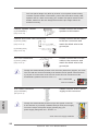
2.1 CPU Installation
For the installation of Intel 1155-Pin CPU,
please follow the steps below.
Before you insert the 1155-Pin CPU into the socket, please check if the
CPU surface is unclean or if there is any bent pin on the socket. Do not
force to insert the CPU into the socket if above situation is found. Other-
wise, the CPU will be seriously damaged.
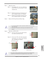
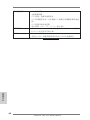
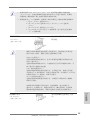
1155-Pin Socket Overview
Con ta ct Ar ra y
Soc ke t Bo dy
Loa d Le ve r
Loa d Pl at e
English

13
ASRock H61 Pro Motherboard
English
Step 1. Open the socket:
Step 1-1. Disengaging the lever by depressing
down and out on the hook to clear
retention tab.
Step 1-2. Rotate the load lever to fully open po-
sition at approximately 135 degrees.
Step 1-3. Rotate the load plate to fully open po-
sition at approximately 100 degrees.
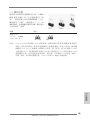
Step 2. Remove PnP Cap (Pick and Place Cap).
1. It is recommended to use the cap tab to handle and avoid kicking
off the PnP cap.
2. This cap must be placed if returning the motherboard for after
service.
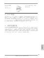
Step 3. Insert the 1155-Pin CPU:
Step 3-1. Hold the CPU by the edges where
are marked with black lines.
Step 3-2. Orient the CPU with IHS (Integrated
Heat Sink) up. Locate Pin1 and the
two orientation key notches.
For proper inserting, please ensure to match the two orientation key
notches of the CPU with the two alignment keys of the socket.
black line
Pin1
alignment key
alignment key
Pin1
1155-Pin CPU
1155-Pin Socket
orientation key notch
orientation key notch

14
ASRock H61 Pro Motherboard
English
Step 3-3. Carefully place the CPU into the
socket by using a purely vertical mo-
tion.
Step 3-4. Verify that the CPU is within the sock-
et and properly mated to the orient
keys.
Step 4. Close the socket:
Step 4-1. Rotate the load plate onto the IHS.
Step 4-2. While pressing down lightly on load
plate, engage the load lever.
Step 4-3. Secure load lever with load plate tab
under retention tab of load lever.
2.2 Installation of CPU Fan and Heatsink
For proper installation, please kindly refer to the instruction manuals of your CPU
fan and heatsink.
Below is an example to illustrate the installation of the heatsink for 1155-Pin CPU.
Step 1. Apply thermal interface material onto center of
IHS on the socket surface.
Step 2. Place the heatsink onto the socket. Ensure
fan cables are oriented on side closest to the
CPU fan connector on the motherboard (CPU_
FAN1, see page 2, No. 2).
Step 3. Align fasteners with the motherboard through-
holes.
Step 4. Rotate the fastener clockwise, then press
down on fastener caps with thumb to install
and lock. Repeat with remaining fasteners.
If you press down the fasteners without rotating them clockwise, the
heatsink cannot be secured on the motherboard.
Step 5. Connect fan header with the CPU fan connector on the motherboard.
Step 6. Secure excess cable with tie-wrap to ensure cable does not interfere with
fan operation or contact other components.
Appl y T he rm al
Inte rf ac e Materia l
Fan c ab les on s ide
clos es t to M B h eader
Fast en er slots
poin ti ng stra ig ht out
Pres s D own
(4 Pla c e s)
Please be noticed that this motherboard supports Combo Cooler
Option (C.C.O.), which provides the exible option to adopt three dif-
ferent CPU cooler types, Socket LGA 775, LGA 1155 and LGA 1156.
The white throughholes are for Socket LGA
1155/1156 CPU fan.

15
ASRock H61 Pro Motherboard
English
2.3 Installation of Memory Modules (DIMM)
This motherboard provides two 240-pin DDR3 (Double Data Rate 3) DIMM slots,
and supports Dual Channel Memory Technology. For dual channel configuration,
you always need to install two identical (the same brand, speed, size and chip-
type) memory modules in the DDR3 DIMM slots to activate Dual Channel Memory
Technology. Otherwise, it will operate at single channel mode.
1. It is not allowed to install a DDR or DDR2 memory module into
DDR3 slot;otherwise, this motherboard and DIMM may be
damaged.
2. If you install only one memory module or two non-identical
memory modules, it is unable to activate the Dual Channel
Memory Technology.
3. Some DDR3 1GB double-sided DIMMs with 16 chips may not
work on this motherboard. It is not recommended to install them
on this motherboard.
notch
break
notch
break
Installing a DIMM
Please make sure to disconnect power supply before adding or
removing DIMMs or the system components.
Step 1. Unlock a DIMM slot by pressing the retaining clips outward.
Step 2. Align a DIMM on the slot such that the notch on the DIMM matches the
break on the slot.
The DIMM only ts in one correct orientation. It will cause permanent
damage to the motherboard and the DIMM if you force the DIMM into
the slot at incorrect orientation.
Step 3. Firmly insert the DIMM into the slot until the retaining clips at both ends
fully snap back in place and the DIMM is properly seated.

16
ASRock H61 Pro Motherboard
English
2.4 Expansion Slots (PCI Express Slots)
There are 6 PCI Express slots on this motherboard.
PCIE slots:
PCIE1 / PCIE3 / PCIE4 / PCIE5 / PCIE6 (PCIE 2.0 x1 slot; White) is
used for PCI Express cards with x1 lane width cards, such as Gigabit
LAN card, SATA2 card, etc.
PCIE2 (PCIE 3.0 x16 slot; Blue) is used for PCI Express x16 lane width
graphics cards.
Only PCIE2 slot supports Gen 3 speed. To run the PCI Express in Gen
3 speed, please install an Ivy Bridge CPU. If you install a Sandy Bridge
CPU, the PCI Express will run only at PCI Express Gen 2 speed.
Installing an expansion card
Step 1. Before installing the expansion card, please make sure that the power
supply is switched off or the power cord is unplugged. Please read the
documentation of the expansion card and make necessary hardware
settings for the card before you start the installation.
Step 2. Remove the system unit cover (if your motherboard is already installed
in a chassis).
Step 3. Remove the bracket facing the slot that you intend to use. Keep the
screws for later use.
Step 4. Align the card connector with the slot and press rmly until the card is
completely seated on the slot.
Step 5. Fasten the card to the chassis with screws.
Step 6. Replace the system cover.

17
ASRock H61 Pro Motherboard
English
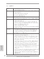
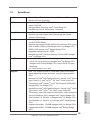
2.5 Jumpers Setup
The illustration shows how jumpers are
setup. When the jumper cap is placed on
pins, the jumper is “Short”. If no jumper cap
is placed on pins, the jumper is “Open”. The
illustration shows a 3-pin jumper whose
pin1 and pin2 are “Short” when jumper cap
is placed on these 2 pins.
Jumper Setting Description
Clear CMOS Jumper
(CLRCMOS1)
(see p.2, No. 9)
Note: CLRCMOS1 allows you to clear the data in CMOS. To clear and reset the
system parameters to default setup, please turn off the computer and unplug
the power cord from the power supply. After waiting for 15 seconds, use a
jumper cap to short pin2 and pin3 on CLRCMOS1 for 5 seconds. However,
please do not clear the CMOS right after you update the BIOS. If you need
to clear the CMOS when you just nish updating the BIOS, you must boot
up the system rst, and then shut it down before you do the clear-CMOS ac-
tion. Please be noted that the password, date, time, user default prole, 1394
GUID and MAC address will be cleared only if the CMOS battery is removed.
Clear CMOSDefault

18
ASRock H61 Pro Motherboard
English
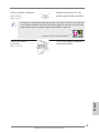
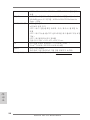
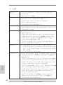
2.6 Onboard Headers and Connectors
Onboard headers and connectors are NOT jumpers. Do NOT place
jumper caps over these headers and connectors. Placing jumper caps
over the headers and connectors will cause permanent damage of the
motherboard!
Serial ATAII Connectors These four Serial ATAII
(SATA2_0: see p.2, No. 12)
(SATAII) connectors support
(SATA2_1: see p.2, No. 15)
SATA data cables for internal
(SATA2_2: see p.2, No. 11)
storage devices. The current
(SATA2_3: see p.2, No. 14)
SATAII interface allows up to
3.0 Gb/s data transfer rate.
Serial ATA (SATA) Either end of the SATA data
Data Cable cable can be connected to the
(Optional)
SATA / SATAII hard disk or the
SATAII connector on this
motherboard.
USB 2.0 Headers Besides six default USB 2.0
(9-pin USB6_7)
ports on the I/O panel, there
(see p.2 No. 18)
are two USB 2.0 headers on
this motherboard. Each
USB 2.0 header can support
two USB 2.0 ports.
(9-pin USB8_9)
(see p.2 No. 17)
1
U SB_PWR
P-8
GND
DUMMY
U SB_PWR
P +8
GND
P-9
P +9
SATA2_2
SATA2_3
SATA2_0
SATA2_1
Infrared Module Header This header supports an
(5-pin IR1)
optional wireless transmitting
(see p.2 No. 13)
and receiving infrared module.
1
IRTX
+5VSB
DUMMY
IRRX
GND

19
ASRock H61 Pro Motherboard
English
J _SENSE
O UT2_L
1
M IC_RET
P RESENCE#
GND
O UT2_R
M IC2_R
M IC2_L
OUT_RET
Front Panel Audio Header This is an interface for front
(9-pin HD_AUDIO1)
panel audio cable that allows
(see p.2 No. 20)
convenient connection and
control of audio devices.
1. High Denition Audio supports Jack Sensing, but the panel wire on
the chassis must support HDA to function correctly. Please follow the
instruction in our manual and chassis manual to install your system.
2. If you use AC’97 audio panel, please install it to the front panel audio
header as below:
A. Connect Mic_IN (MIC) to MIC2_L.
B. Connect Audio_R (RIN) to OUT2_R and Audio_L (LIN) to OUT2_L.
C. Connect Ground (GND) to Ground (GND).
D. MIC_RET and OUT_RET are for HD audio panel only. You don’t
need to connect them for AC’97 audio panel.
System Panel Header This header accommodates
(9-pin PANEL1)
several system front panel
(see p.2 No. 16)
functions.
Connect the power switch, reset switch and system status indicator on the
chassis to this header according to the pin assignments below. Note the
positive and negative pins before connecting the cables.
PWRBTN (Power Switch):
Connect to the power switch on the chassis front panel. You may congure
the way to turn off your system using the power switch.
RESET (Reset Switch):
Connect to the reset switch on the chassis front panel. Press the reset
switch to restart the computer if the computer freezes and fails to perform a
normal restart.
PLED (System Power LED):
Connect to the power status indicator on the chassis front panel. The LED
is on when the system is operating. The LED keeps blinking when the sys-
tem is in S1 sleep state. The LED is off when the system is in S3/S4 sleep
state or powered off (S5).
HDLED (Hard Drive Activity LED):
Connect to the hard drive activity LED on the chassis front panel. The LED
is on when the hard drive is reading or writing data.

20
ASRock H61 Pro Motherboard
English
Chassis Speaker Header Please connect the chassis
(4-pin SPEAKER 1)
speaker to this header.
(see p.2 No. 10)
CPU Fan Connectors Please connect the CPU fan
(4-pin CPU_FAN1)
cable to the connector and
(see p.2 No. 2)
match the black wire to the
ground pin.
Chassis and Power Fan Connectors Please connect the fan cables
(4-pin CHA_FAN1)
to the fan connectors and
(see p.2 No. 6)
match the black wire to the
ground pin.
(4-pin PWR_FAN1)
(see p.2 No. 27)
Though this motherboard provides 4-Pin CPU fan (Quiet Fan) support, the 3-Pin
CPU fan still can work successfully even without the fan speed control function.
If you plan to connect the 3-Pin CPU fan to the CPU fan connector on this
motherboard, please connect it to Pin 1-3.
3-Pin Fan Installation
Pin 1-3 Connected
ATX Power Connector Please connect an ATX power
(24-pin ATXPWR1)
supply to this connector.
(see p.2 No. 5)
12
1
24
13
20-Pin ATX Power Supply Installation
Though this motherboard provides 24-pin ATX power connector,
it can still work if you adopt a traditional 20-pin ATX power supply.
To use the 20-pin ATX power supply, please plug your
power supply along with Pin 1 and Pin 13.
12
1
24
13
The front panel design may differ by chassis. A front panel module mainly
consists of power switch, reset switch, power LED, hard drive activity LED,
speaker and etc. When connecting your chassis front panel module to this
header, make sure the wire assignments and the pin assign-ments are
matched correctly.
GND
+ 12V
CPU_FAN_SPEED
FAN_S PEED_CONTROL
1 2 3 4
FAN_SPEED_CONTROL
GND
+12V
PWR_FAN_SPEED
Page is loading ...
Page is loading ...
Page is loading ...
Page is loading ...
Page is loading ...
Page is loading ...
Page is loading ...
Page is loading ...
Page is loading ...
Page is loading ...
Page is loading ...
Page is loading ...
Page is loading ...
Page is loading ...
Page is loading ...
Page is loading ...
Page is loading ...
Page is loading ...
Page is loading ...
Page is loading ...
Page is loading ...
Page is loading ...
Page is loading ...
Page is loading ...
Page is loading ...
Page is loading ...
Page is loading ...
Page is loading ...
Page is loading ...
Page is loading ...
Page is loading ...
Page is loading ...
Page is loading ...
Page is loading ...
Page is loading ...
Page is loading ...
Page is loading ...
Page is loading ...
Page is loading ...
Page is loading ...
Page is loading ...
Page is loading ...
Page is loading ...
Page is loading ...
Page is loading ...
Page is loading ...
Page is loading ...
Page is loading ...
-
 1
1
-
 2
2
-
 3
3
-
 4
4
-
 5
5
-
 6
6
-
 7
7
-
 8
8
-
 9
9
-
 10
10
-
 11
11
-
 12
12
-
 13
13
-
 14
14
-
 15
15
-
 16
16
-
 17
17
-
 18
18
-
 19
19
-
 20
20
-
 21
21
-
 22
22
-
 23
23
-
 24
24
-
 25
25
-
 26
26
-
 27
27
-
 28
28
-
 29
29
-
 30
30
-
 31
31
-
 32
32
-
 33
33
-
 34
34
-
 35
35
-
 36
36
-
 37
37
-
 38
38
-
 39
39
-
 40
40
-
 41
41
-
 42
42
-
 43
43
-
 44
44
-
 45
45
-
 46
46
-
 47
47
-
 48
48
-
 49
49
-
 50
50
-
 51
51
-
 52
52
-
 53
53
-
 54
54
-
 55
55
-
 56
56
-
 57
57
-
 58
58
-
 59
59
-
 60
60
-
 61
61
-
 62
62
-
 63
63
-
 64
64
-
 65
65
-
 66
66
-
 67
67
-
 68
68


ASROCK H61 Pro Quick start guide
- Category
- Motherboards
- Type
- Quick start guide
Ask a question and I''ll find the answer in the document
Finding information in a document is now easier with AI
