Tripp Lite 3-Phase Switched 0U PDUs 8 Owner's manual
- Category
- Power distribution units (PDUs)
- Type
- Owner's manual
This manual is also suitable for

1
Warranty
Registration:
register online today for a
chance to win a FREE Tripp Lite
product—www.tripplite.com/warranty
Owner’s Manual
3-Phase Switched 0U Power
Distribution Units
208V MODELS
PDU3VSR6H50A • PDU3VSR6G60A
(Series Number: AG-0065) • (Series Number: AG-0063)
400V MODELS
PDU3XVSRHWA • PDU3XVSRHWB PDU3XVSR6G32A • PDU3XVSR6G32B
(Series Number: AG-0057) (Series Number: AG-0080)
PDU3XVSR6L2230 • PDU3XVSR6L2230B PDU3XVSR6G60A • PDU3XVSR6G60B
(Series Number: AG-0056) (Series Number: AG-0093)
PDU3XVSR6G30A • PDU3XVSR6G30B PDU3XVSR6G63A • PDU3XVSR6G63B
(Series Number: AG-0096) (Series Number: AG-0094)
Important Safety Instructions 2
Installation 3
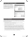
Digital Display 8
Using the Digital Display 10
Features 16
Configuration and Operation 18
Service 18
Warranty and Warranty Registration 19
Español 20
Français 39
Русский 58
1111 W. 35th Street, Chicago, IL 60609 USA • www.tripplite.com/support
Copyright © 2013 Tripp Lite. All rights reserved.
13-09-017-9332B8.indb 1 9/5/2013 4:26:45 PM

2
Important Safety Instructions
SAVE THESE INSTRUCTIONS
This manual contains instructions and warnings that should be followed during
the installation, operation, and storage of this product. Failure to heed these
instructions and warnings may affect the product warranty.
• The PDU provides convenient multiple outlets, but it DOES NOT provide surge or line noise
protection for connected equipment.
• The PDU is designed for indoor use only in a controlled environment away from excess
moisture, temperature extremes, conductive contaminants, dust or direct sunlight.
• Do not connect the PDU to an ungrounded outlet or to extension cords or adapters that
eliminate the connection to ground.
• The power requirement for each piece of equipment connected to the PDU must not exceed
the individual outlet’s load rating.
• The total power requirement for equipment connected to the PDU must not exceed the
maximum load rating for the PDU.
• Do not drill into or attempt to open any part of the PDU housing. There are no user-serviceable
parts inside.
• Do not attempt to modify the PDU, including the input plugs and power cables.
• Do not attempt to use the PDU if any part of it becomes damaged.
• Do not attempt to mount the PDU to an insecure or unstable surface.
• Use of this equipment in life support applications where failure of this equipment can
reasonably be expected to cause the failure of the life support equipment or to signicantly
affect its safety or effectiveness is not recommended. Do not use this equipment in the
presence of a ammable anesthetic mixture with air, oxygen or nitrous oxide.
• Never attempt to install electrical equipment during a thunderstorm.
• Keep indoor ambient temperature between 32°F and 104°F (0°C and 40°C).
• Connect the PDU to an outlet that is in accordance with your local building codes and that is
adequately protected against excess currents, short circuits and earth faults.
• Do not attempt to open the PDU; there are no user-serviceable parts inside.
• The PDU must be installed by a qualied technician only.
13-09-017-9332B8.indb 2 9/5/2013 4:26:45 PM

1-1 1-2
1-4
1-3
1-5
A
B
3
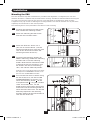
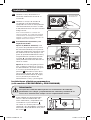
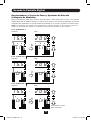
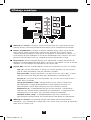
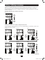
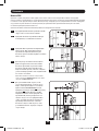
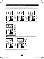
Installation
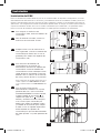
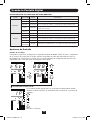
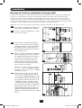
Mounting the PDU
Note: The illustrations may differ somewhat from your PDU model. Regardless of configuration, the user must
determine the fitness of hardware and procedures before mounting. The PDU and included hardware are designed
for common rack and rack enclosure types and may not be appropriate for all applications. Exact mounting
configurations may vary. Screws for attaching the mounting brackets to the PDU are included. Use only the screws
supplied by the manufacturer or their exact equivalent.
Note: Mounting buttons come preinstalled to the PDU for toolless mounting.
1-1
To attach the mounting brackets to the
PDU, remove the mounting buttons.
1-2
Attach the mounting brackets to the
PDU with the included screws.
1-3
Attach the PDU to a vertical rail in
your rack or rack enclosure. (Use the
mounting hardware that came with your
rack or rack enclosure to attach the
mounting brackets to the rail.)
1-4
To reinstall the mounting buttons for
toolless mounting, remove the mounting
brackets then install the mounting
buttons onto the PDU. Position the PDU
as desired in the rack enclosure, align
the buttons with the rack mounting
slots, and slide the PDU into position.
Note: Be sure to insert the 2 buttons into either
the upper hole at each end of the PDU or into
the lower hole at each end of the PDU.
1-5
To install the PDU with its outlets facing
the rear of the rack, use the included
PDUMVROTATEBRKT accessory. First,
attach the mounting button
A
to the
V-shaped bracket
B
using the included
screw and washer. Then, use the
button-mount slot to attach the bracket
to the PDU and the mounting button to
attach the PDU to the rack. The bracket
effectively repositions the mounting
brackets allowing for the PDU outlets to
face the rear of the rack.
13-09-017-9332B8.indb 3 9/5/2013 4:26:46 PM

4
Installation
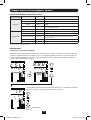
Connecting the PDU
2-1
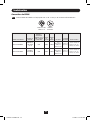
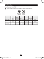
Each 208V model is equipped with 1 of 2 different input plugs.
60A Blue IEC
309 3P+E
Model Name Input Plug
Max Input
Amps (Limited
by Input Cord
and Plug)
Input
Voltage
Output
Voltage Breakers
Cord
Length
Outlets
PDU3VSR6G60A
60A Blue IEC
309 3P+E
45A 208V 208V
6 x Double
Pole, 20A
Branch-Rated
6 ft.
(1.8 m)
18 Total; 6 Banks of
(2) C19 and (1) C13
PDU3VSR6H50A
HUBBLE
CS8365C
40A 208V 208V
6 x Double
Pole, 20A
Branch-Rated
6 ft.
(1.8 m)
18 Total; 6 Banks of
(2) C19 and (1) C13
HUBBLE
CS8365C
13-09-017-9332B8.indb 4 9/5/2013 4:26:47 PM

5
Installation
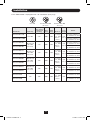
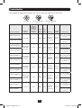
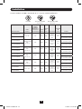
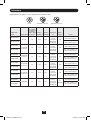
Each 400V model is equipped with 1 of 3 different input plugs.
63A Red IEC 309
3P+N+E
L22-30P 32A Red IEC 309
3P+N+E
Model Name Input Plug
Max Input
Amps (Limited
by Input Cord
and Plug)
Input
Voltage
Output
Voltage Breakers
Cord
Length
Outlets
PDU3XVSR6L2230
L22-30P 24A 400V 230V
6 x Single
Pole, 20A
Branch-
Rated
6 ft.
(1.8 m)
24 Total; 6 Banks of
(2) C19 and (2) C13
PDU3XVSR6L2230B
30 Total; 6 Banks of
(1) C19 and (4) C13
PDU3XVSR6G30A
30/32A Red
IEC 309
3P+N+E
24A 400V 230V
6 x Single
Pole, 20A
Branch-
Rated
6 ft.
(1.8 m)
24 Total; 6 Banks of
(2) C19 and (2) C13
PDU3XVSR6G30B
30 Total; 6 Banks of
(1) C19 and (4) C13
PDU3XVSR6G32A
30/32A Red
IEC 309
3P+N+E
32A 400V 230V
6 x Single
Pole, 20A
Branch-
Rated
6 ft.
(1.8 m)
24 Total; 6 Banks of
(2) C19 and (2) C13
PDU3XVSR6G32B
30 Total; 6 Banks of
(1) C19 and (4) C13
PDU3XVSR6G60A
60/63A Red
IEC 309
3P+N+E
35A 400V 230V
6 x Single
Pole, 20A
Branch-
Rated
6 ft.
(1.8 m)
24 Total; 6 Banks of
(2) C19 and (2) C13
PDU3XVSR6G60B
30 Total; 6 Banks of
(1) C19 and (4) C13
PDU3XVSR6G63A
60/63A Red
IEC 309
3P+N+E
40A 400V 230V
6 x Single
Pole, 20A
Branch-
Rated
6 ft.
(1.8 m)
24 Total; 6 Banks of
(2) C19 and (2) C13
PDU3XVSR6G63B
30 Total; 6 Banks of
(1) C19 and (4) C13
PDU3XVSRHWA
N/A 40A 400V 230V
6 x Single
Pole, 20A
Branch-
Rated
N/A
24 Total; 6 Banks of
(2) C19 and (2) C13
PDU3XVSRHWB
30 Total; 6 Banks of
(1) C19 and (4) C13
13-09-017-9332B8.indb 5 9/5/2013 4:26:47 PM

6
5
4
LOAD L2
BANK 1
3
1211
10
B4
B3
9
87
LOAD L1
BANK 2
LOAD L3
BANK 1
LOAD L2
BANK 1
STATUS
LINK
RESET
ENVIROSENSE
CONFIG
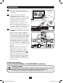
2-2
2-3
2-4
B
2-5
A
A B
6
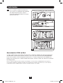
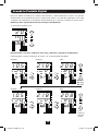
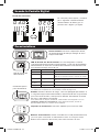
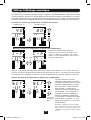
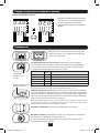
Installation
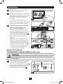
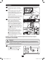
2-2
Connect the input plug to your facility’s
compatible AC power source.
2-3
Connect your equipment’s input plugs to
the appropriate outlets on the PDU. The
LED near each outlet illuminates when
the outlet is ready to distribute live
AC power.
Note: It is recommended that you do not
connect a live load to the PDU. If the load you
intend to connect has an ON/OFF switch, please
turn the switch to OFF prior to connection.
2-4
Optional Cord Retention Procedure
Option 1 (Select Models): Use
the bridge lances located near each
receptacle to retain power cords. Tie
each equipment power cord to a bridge
lance by looping the cord and securing
it with one of the included cable ties
A
.
Make sure each cord can be unplugged
from the PDU without removing the
cable tie.
Option 2: Use the included C14 and
C20 plastic sleeves to secure plugs to
receptacles. Attach the sleeve to the
plug, making sure that the pull tabs
B
remain outside the plug and that the t
is secure. To unplug equipment properly,
use the pull tabs to remove the plug
and sleeve from the receptacle.
For Installation
Purposes Only
Hardwire Installations
(PDU3XVSRHWA & PDU3XVSRHWB models only)
2-5
These models do not come equipped
with an input cable. Conduit and
adapters are installed to the endplate
A
,
wires are channeled through the conduit
and adapters to the terminal block,
located behind the access plate
B
.
WARNING
Only qualied personnel should perform hardwire installations. Wire codes and
requirements differ from area to area. Be sure to conform to local electrical
requirements.
13-09-017-9332B8.indb 6 9/5/2013 4:26:49 PM

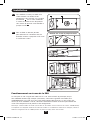
2-6
Remove Access Plate Screws
7
Installation
Networking the PDU
Your PDU can receive IP address assignments via DHCP server (dynamic) or static (manual)
addressing methods. See the SNMPWEBCARD installation guide on the included CD or visit
www.tripplite.com/manuals. If you are uncertain which method to use, contact your network
administrator for assistance before continuing the conguration process.
Note: The MAC address of the PDU (12-digit string in this format: 000667xxxxxx) is printed on a label attached
to the PDU enclosure. For static IP address assignments, use the RJ-45 to DB9 configuration cable (part
number 73-1243) included with the PDU.
2-6
To access the terminal block to make
input wire connections, remove the
access plate located on the back side of
the PDU.
Ground Terminal
X
Y
Z
N
13-09-017-9332B8.indb 7 9/5/2013 4:26:50 PM

A
BC DE
8
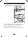
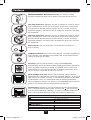
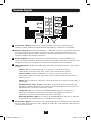
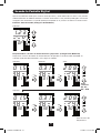
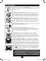
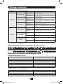
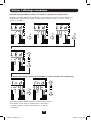
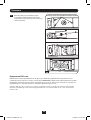
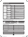
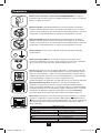
Digital Display
A
3-Digit Display: Shows measured or calculated values such as Amperage, Kilowatts,
Voltage, Power Unbalance Percentage, Temperature and Humidity.
B
Arrow Buttons: Scroll through indicated Outlet, Input, Bank, Power, Load Balance, Sensor
and Display Brightness options using these buttons. A long press of the up or down arrow
buttons allows the user to skip to the next sequential measurement category.
C
Mode Button: When a menu option is selected using the Arrow Buttons, the Mode Button
scrolls through the sub-options within each category. Sub-options are shown by the
Indicator LEDs.
D
Indicator LEDs: Lit LED indicates which value is being displayed on the 3-digit screen.
Amps (A): When selected, the load on the selected Input Phase (L#), Load Bank (B#)
or Outlet (##) is displayed in amps.
Wattage (kW): When selected, the load on the selected Load Bank (B#), Outlet (##)
or Total Output Power (OP) is displayed in kW.
Voltage (V): Input Phase (L#), Load Bank (B#) or Outlet (##) voltage is displayed.
Unbalanced Load (%UB): When lit, the display shows the unbalanced load
percentage deviance from the average measured value. The percentage for the phase
with the highest deviance is displayed.
Temperature (T): If Tripp Lite ENVIROSENSE is connected, the ambient temperature
will be displayed when this option is selected. The temperature is displayed in Celsius
by default, but can be switched to Fahrenheit.
Relative Humidity (%RH): If Tripp Lite ENVIROSENSE is connected, the relative
humidity percentage will be displayed when this option is selected.
E
2-Digit Display: This display indicates which Input Phase (L#), Load Balance (UB), Load
Bank (B#), Output Power (OP), Outlet (##) or Sensor (S#) option is selected.
13-09-017-9332B8.indb 8 9/5/2013 4:26:50 PM

65
4
LOAD L2
BANK 1
LOAD L1
BANK 1
3
21
LOAD L1
BANK 1
1211
10
LOAD L1
BANK 2
LOAD L3
BANK 1
9
87
LOAD L1
BANK 2
LOAD L3
BANK 1
LOAD L2
BANK 1
STATUS
LINK
RESET
ENVIROSENSE
1817
16
LOAD L3
BANK 2
LOAD L2
BANK 2
15
1413
LOAD L3
BANK 2
LOAD L2
BANK 2
CONFIG
STATUS
LINK
RESET
ENVIROSENSE
CONFIG
B1
B3
B5
B2
B4
B6
9
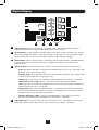
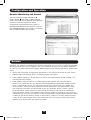
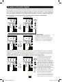
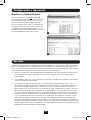
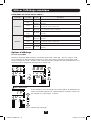
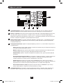
Digital Display
Load Bank Receptacle Location
Display References for 208V Models
LOAD BANKS REFERENCE
SILKSCREEN LABEL DESCRIPTION 2-DIGIT DISPLAY REFERENCE
L1-L2, BANK 1 B1
L2-L3, BANK 2 B2
L3-L1, BANK 3 B3
L1-L2, BANK 4 B4
L2-L3, BANK 5 B5
L3-L1, BANK 6 B6
INPUT PHASE REFERENCE
INPUT PHASE REPORTED 2-DIGIT DISPLAY REFERENCE
INPUT PHASE L1 – L2 L1
INPUT PHASE L2 – L3 L2
INPUT PHASE L3 – L1 L3
Button Response Denitions:
Conguration
1
Switch Action Control Function
Standard
Up Pushbutton
Depress ½ sec
Sequentially, moves up one selection in
the menu.
Depress 3 sec
Advances up to the next measurement
category.
Down Pushbutton
Depress ½ sec
Sequentially, moves down one selection in
the menu.
Depress 3 sec
Advances down to the next measurement
category.
Mode Pushbutton
Depress ½ sec
Displays available options for a given
measurement category.
Depress 3 sec
Selects the chosen available option for a given
conguration category.
Alternate
Up Pushbutton
Depress ½ sec
Sequentially, moves down one selection in
the menu.
Depress 3 sec
Advances down to the next measurement
category.
Down Pushbutton
Depress ½ sec
Sequentially, moves up one selection in the
menu.
Depress 3 sec
Advances up to the next measurement
category.
Mode Pushbutton
Depress ½ sec
Displays available options for a given
measurement category.
Depress 3 sec
Selects the chosen available option for a given
conguration category.
1
Congured via Conguration Category item “Outlet Indicator LED Color Code Options”.
13-09-017-9332B8.indb 9 9/5/2013 4:26:51 PM

i 5.5
L i
2 0 8
L i
i 5.5
L2
2 0 8
L2
i 5.5
L3
2 0 8
L3
10
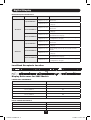
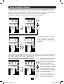
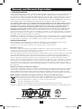
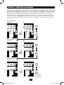
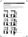
Using the Digital Display
Scrolling Through Input Phases and Options
(Measurement Category)
Press Mode button to toggle between options and data within a menu. A momentary press of the
arrow buttons switches between menus. A long press skips between measurement categories.
The scrolling pattern of the display is outlined below. Note: Three dashes will be shown in the
3-digit display when the input phase voltage is unknown, due to abnormal tripped breaker
conditions.
Input Phase 1
Input Phase 2
Input Phase 3
Amps
Amps
Amps
Volts
Volts
Volts
To Unbalanced Load Detect
13-09-017-9332B8.indb 10 9/5/2013 4:26:52 PM

2 0
i 0.5 2. i 8
2. i 8
2 0 8
i 0.5 2 0 8
i.2 3
OP
11
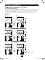
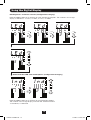
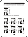
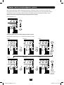
Using the Digital Display
Press Mode button to toggle between options and data within a menu. A momentary press of the
arrow buttons switches between menus. A long press skips between measurement categories.
The scrolling pattern of the display is outlined below.
Unbalanced Load Detect (Measurement Category)
Scrolling Through Load Banks and Options (Measurement Category)
Scroll through Load Banks 2-6 using Mode button.
Amps
Amps
Kilowatts
Kilowatts
Volts
Volts
Phase Imbalance %
To Total
Output
Power
Banks
#2, #3,
#4, #5
13-09-017-9332B8.indb 11 9/5/2013 4:26:52 PM

i 0.5 2. i 8
2. i 8
2 0 8
i 0.5 2 0 8
i.2 3
OP
0 i.5
0 i
0.3 i
0.3 i
2 0 8
30 30
2 0 8
30
0 i 0 i
0 i.5
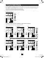
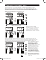
12
Outlet
#2, #3,
#4…#30
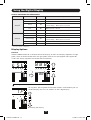
Using the Digital Display
Press Mode button to toggle between options and data within a menu. A momentary press of the
arrow buttons switches between menus. A long press skips between measurement categories.
The scrolling pattern of the display is outlined below.
Total Output Power (Measurement Category)
Kilowatts
Scrolling Through Outlets and Options (Measurement Category)
Scroll through all available outlets using Mode button. Highest outlet number varies by model.
Amps
Amps
Kilowatts
Kilowatts
Volts
Volts
To
Temperature
Readings
13-09-017-9332B8.indb 12 9/5/2013 4:26:53 PM

4 0
5 i 5 i
8 0
C F
C – F C – F
4
Y
3
I 2
I 2
13
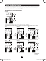
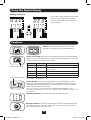
Using the Digital Display
These options are only available when a sensor such as Tripp Lite’s ENVIROSENSE is attached
(sold separately). Press Mode button to toggle between options and data within a menu. A
momentary press of the arrow buttons switches between menus. A long press skips between
measurement categories. The scrolling pattern of the display is outlined below.
Scrolling Through Temperature Readings (Measurement Category)
Humidity (%RH)Temperature (T)
Temperature Unit Options (Conguration Category)
3 Seconds
Hold Mode button for 3 seconds to
switch between options. The letter
in the 2-digit display indicates the
selected unit, C for Celsius and F for
Fahrenheit.
Press Mode button to toggle between options and data within a menu. A momentary press of the
arrow buttons switches between menus. A long press skips between measurement categories.
The scrolling pattern of the display is outlined below.
Scroll Function Options (Conguration Category)
When enabled, the Auto Scroll
function displays data for
Input Phases, Load Unbalance
and Load Banks in 4-second
intervals. Y indicates the
function is enabled; N indicates
that it is disabled. Pressing any
button interrupts the auto scroll
function, allowing the user to
navigate between menu options.
If no button is pressed, there is
a 10 second timeout.
Note: Hold Mode button for 3
seconds to switch between options.
The letter in the 2-digit display
indicates the selected option.
To LED
Bright-
ness
13-09-017-9332B8.indb 13 9/5/2013 4:26:54 PM

4
Y
3
I 2
I 2
4
Y
3
I 2
I 2
4
Y
3
I 2
I 2
14
Using the Digital Display
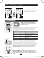
Outlet Indicator LED Color Code Options (Conguration Category)
Hold the Mode button for 3 seconds to switch between options.
The number in the 2-digit display indicates the selected scheme.
1=Standard, 2=Alternate
LED Brightness and Color Scheme (Conguration Category)
Hold the Mode button for 3 seconds to scroll through each option. The number in the 2-digit
display is dened as: 1=25%; 2=50%; 3=75%; 4=100%
13-09-017-9332B8.indb 14 9/5/2013 4:26:56 PM

i
88
i P
0 3.0
8 8 8
0 i
0 3.0
0 i
15
Using the Digital Display
Display Options
LED Test
Hold the Mode button for 3 seconds to test the display. All LEDs and display segments will light
green, while all Load Indicator LEDs will light yellow. Please visit www.tripplite.com/support for
issues with display segment or Indicator LED functionality.
Viewing the IP Address
At any point, pressing both of the arrow buttons simultaneously for 1/2
second displays the unit’s IP address in the 2-digit display.
OUTLET INDICATOR LED DEFINITIONS:
LED Conguration LED Color Outlet Status Description
Standard
1
Off Off Outlet power is absent
Green On Circuit breaker is on – Outlet power is present
Yellow On
Outlet current has exceeded 80% of the outlet
current rating – Outlet power is present
Red Off
Outlet voltage is below the Low Voltage threshold –
Outlet power is absent
Red Flashing Off Circuit breaker has tripped – Outlet power is absent
Alternate
Off Off Outlet power is absent
Red On Circuit breaker is on – Outlet power is present
Red Flashing On
Outlet current has exceeded 80% of the outlet
current rating – Outlet power is present
Green Off Outlet is disabled - Outlet power is absent
Green Flashing Off Circuit breaker has tripped – Outlet power is absent
1
This is the default conguration.
To Rotating the Display
13-09-017-9332B8.indb 15 9/5/2013 4:26:57 PM

i
88
i P
0 3.0
8 8 8
0 i
0 3.0
0 i
16
Using the Digital Display
Rotating the Display
At any point, pressing both of the arrow
buttons simultaneously and holding
for 3 seconds rotates the 2-digit and
3-digit displays.
Features
Outlets: During normal operation, the outlets
distribute AC power to connected equipment.
Outlet Status LED: Once the unit is powered on, each outlet individually
ramps up and each Outlet Status LED will illuminate when the associated
outlet is ready to distribute live AC power.
LED Color Outlet Status Comments/Notes
Green On Normal operation.
Yellow On Outlet current has exceeded 80% of the outlet
current rating.
Red Off Outlet voltage is below the Low Voltage threshold.
Flashing Red Off Circuit breaker for this bank has tripped.
Off Off Outlet is powered off.
Note: Colors noted here reflect standard LED configuration. See chart on page 15
for full LED color definitions.
C13 C19
Circuit Breaker: There are 6 Load Banks, each protected by a circuit
breaker. If the connected equipment load exceeds the Maximum Load
Rating for that bank of the PDU, the circuit breaker will trip. Disconnect
excess load and reset the breaker.
Note: Each breaker comes equipped with a push-to-reset guard to prevent
accidental breaker tripping. To turn off the breaker, insert a flathead screwdriver into
the reset slot.
Mounting Brackets: Use these brackets to mount the PDU.
Mounting Buttons: Come pre-installed on the back side of the PDU and
are used for toolless mounting. Note: Four additional mounting buttons
are included for alternate rack styles.
Outlet Status LED
Push-to-Reset Guard
13-09-017-9332B8.indb 16 9/5/2013 4:26:58 PM

CONFIG
A B
17
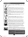
Features
SNMP Reset Button: Press the reset button for 3 seconds to reboot the
PDU’s network card. Rebooting the network card will not erase network
settings or interrupt AC power.
PS/2 Port: Use this port to connect a Tripp Lite ENVIROSENSE
environmental sensor to provide remote temperature/humidity monitoring
and a dry contact interface to control and monitor alarm, security and
telecom devices. Visit www.tripplite.com for ordering information. Note:
Do not connect a keyboard or mouse to this port.
Ground Screw: Use this to connect any equipment that requires a
chassis ground.
C20 Plug-lock Insert: (Optional) Use the included C20 inserts to secure
plugs to receptacles. Attach the insert to the plug making sure that the
pull tabs remain outside the plug and that the t is secure. To unplug
equipment properly, use the pull tabs to remove the plug and insert from
the receptacle.
RJ-45 Conguration Port: Use this port to provide a direct terminal
connection to a computer with a terminal emulation program. An RJ-45 to
DB9 cable (part number 73-1243) is included with the PDU. If you need
a replacement cable, visit www.tripplite.com for ordering information.
Note: Configuration options can found in the SNMPWEBCARD installation
guide on the included CD or at www.tripplite.com/manuals.
Ethernet Port: Use this RJ-45 jack to connect the PDU to the network
with a standard Ethernet patch cable. The Link LED
A
and Status LED
B
indicate several operating conditions, as shown in the table below. This
port is not compatible with PoE (Power Over Ethernet) applications.
Network Operating Conditions
A
Link LED Color
Off No Network Connection
Flashing Amber 100 Mbps Network Connection
Flashing Green 10 Mbps Network Connection
B
Status LED Color
Off Card Not Initialized
Steady or Flashing Green Card Initialized and Operational
Steady Amber Error - Card Not Initialized
PDUMVROTATEBRKT Mounting Accessory: Use these V-shaped
brackets to mount the PDU with its outlets facing the rear of the rack.
C14 Plug-lock Insert: (Optional) Use the included C14 inserts to secure
plugs to receptacles. Attach the insert to the plug making sure that the
pull tabs remain outside the plug and that the t is secure. To unplug
equipment properly, use the pull tabs to remove the plug and insert from
the receptacle.
13-09-017-9332B8.indb 17 9/5/2013 4:26:59 PM

A
B
18
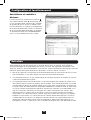
Configuration and Operation
Service
Remote Monitoring and Control
The PDU provides remote monitoring
A
,
outlet control
B
and more via Web browser,
telnet and SNMP-based Network Management
Systems. For more information about
conguration and operation of the PDU via
thePowerAlert Web browser interface, refer to
the SNMPWEBCARD User’s Guide, included on
the CD-ROM bundled with the PDU.
Your Tripp Lite product is covered by the warranty described in this manual. A variety of Extended
Warranty and On-Site Service Programs are also available from Tripp Lite. For more information
on service, visit www.tripplite.com/support. Before returning your product for service, follow these
steps:
1. Review the installation and operation procedures in this manual to ensure that the service
problem does not originate from a misreading of the instructions.
2. If the problem continues, do not contact or return the product to the dealer. Instead, visit
www.tripplite.com/support.
3. If the problem requires service, visit www.tripplite.com/support and click the Product
Returns link. From here you can request a Returned Material Authorization (RMA) number,
which is required for service. This simple on-line form will ask for your unit’s model and
serial numbers, along with other general purchaser information. The RMA number, along
with shipping instructions will be emailed to you. Any damages (direct, indirect, special
or consequential) to the product incurred during shipment to Tripp Lite or an authorized
Tripp Lite service center is not covered under warranty. Products shipped to Tripp Lite or an
authorized Tripp Lite service center must have transportation charges prepaid. Mark the RMA
number on the outside of the package. If the product is within its warranty period, enclose
a copy of your sales receipt. Return the product for service using an insured carrier to the
address given to you when you request the RMA.
13-09-017-9332B8.indb 18 9/5/2013 4:27:00 PM

19
Warranty and Warranty Registration
2- YEAR LIMITED WARRANTY
Seller warrants this product, if used in accordance with all applicable instructions, to be free from original defects
in material and workmanship for a period of 2 years from the date of initial purchase. If the product should
prove defective in material or workmanship within that period, Seller will repair or replace the product, in its sole
discretion. Service under this Warranty can only be obtained by your delivering or shipping the product (with all
shipping or delivery charges prepaid) to: Tripp Lite, 1111 W. 35th Street, Chicago, IL 60609 USA. Seller will pay
return shipping charges. Visit www.tripplite.com/support before sending any equipment back for repair.
THIS WARRANTY DOES NOT APPLY TO NORMAL WEAR OR TO DAMAGE RESULTING FROM ACCIDENT, MISUSE,
ABUSE OR NEGLECT. SELLER MAKES NO EXPRESS WARRANTIES OTHER THAN THE WARRANTY EXPRESSLY
SET FORTH HEREIN. EXCEPT TO THE EXTENT PROHIBITED BY APPLICABLE LAW, ALL IMPLIED WARRANTIES,
INCLUDING ALL WARRANTIES OF MERCHANTABILITY OR FITNESS, ARE LIMITED IN DURATION TO THE
WARRANTY PERIOD SET FORTH ABOVE; AND THIS WARRANTY EXPRESSLY EXCLUDES ALL INCIDENTAL AND
CONSEQUENTIAL DAMAGES. (Some states do not allow limitations on how long an implied warranty lasts,
and some states do not allow the exclusion or limitation of incidental or consequential damages, so the above
limitations or exclusions may not apply to you. This Warranty gives you specic legal rights, and you may have
other rights which vary from jurisdiction to jurisdiction).
WARNING: The individual user should take care to determine prior to use whether this device is suitable, adequate
or safe for the use intended. Since individual applications are subject to great variation, the manufacturer makes
no representation or warranty as to the suitability or tness of these devices for any specic application.
WARRANTY REGISTRATION
Visit www.tripplite.com/warranty today to register the warranty for your new Tripp Lite product.You’ll be
automatically entered into a drawing for a chance to win a FREE Tripp Lite product!*
* No purchase necessary. Void where prohibited. Some restrictions apply. See website for details.
FCC Notice, Class A
This device complies with part 15 of the FCC Rules. Operation is subject to the following two conditions:
(1) This device may not cause harmful interference, and (2) this device must accept any interference received,
including interference that may cause undesired operation.
Note: This equipment has been tested and found to comply with the limits for a Class A digital device, pursuant
to part 15 of the FCC Rules. These limits are designed to provide reasonable protection against harmful
interference when the equipment is operated in a commercial environment. This equipment generates, uses,
and can radiate radio frequency energy and, if not installed and used in accordance with the instruction
manual, may cause harmful interference to radio communications. Operation of this equipment in a residential
area is likely to cause harmful interference in which case the user will be required to correct the interference
at his own expense. The user must use shielded cables and connectors with this equipment. Any changes or
modications to this equipment not expressly approved by Tripp Lite could void the user’s authority to operate
this equipment.
Regulatory Compliance Identication Numbers
For the purpose of regulatory compliance certications and identication, your Tripp Lite product has been assigned
a unique series number. The series number can be found on the product nameplate label, along with all required
approval markings and information. When requesting compliance information for this product, always refer to the
series number. The series number should not be confused with the marking name or model number of the product.
WEEE Compliance Information for Tripp Lite Customers and Recyclers (European Union)
Under the Waste Electrical and Electronic Equipment (WEEE) Directive and implementing regulations,
when customers buy new electrical and electronic equipment from Tripp Lite they are entitled to:
• Send old equipment for recycling on a one-for-one, like-for-like basis
(this varies depending on the country)
• Send the new equipment back for recycling when this ultimately becomes waste
The policy of Tripp Lite is one of continuous improvement. Specications are subject to change without notice.
1111 W. 35th Street, Chicago, IL 60609 USA • www.tripplite.com/support
13-09-017-9332B8.indb 19 9/5/2013 4:27:00 PM
Page is loading ...
Page is loading ...
Page is loading ...
Page is loading ...
Page is loading ...
Page is loading ...
Page is loading ...
Page is loading ...
Page is loading ...
Page is loading ...
Page is loading ...
Page is loading ...
Page is loading ...
Page is loading ...
Page is loading ...
Page is loading ...
Page is loading ...
Page is loading ...
Page is loading ...
Page is loading ...
Page is loading ...
Page is loading ...
Page is loading ...
Page is loading ...
Page is loading ...
Page is loading ...
Page is loading ...
Page is loading ...
Page is loading ...
Page is loading ...
Page is loading ...
Page is loading ...
Page is loading ...
Page is loading ...
Page is loading ...
Page is loading ...
Page is loading ...
Page is loading ...
Page is loading ...
Page is loading ...
Page is loading ...
Page is loading ...
Page is loading ...
Page is loading ...
Page is loading ...
Page is loading ...
Page is loading ...
Page is loading ...
Page is loading ...
Page is loading ...
Page is loading ...
Page is loading ...
Page is loading ...
Page is loading ...
Page is loading ...
Page is loading ...
Page is loading ...
-
 1
1
-
 2
2
-
 3
3
-
 4
4
-
 5
5
-
 6
6
-
 7
7
-
 8
8
-
 9
9
-
 10
10
-
 11
11
-
 12
12
-
 13
13
-
 14
14
-
 15
15
-
 16
16
-
 17
17
-
 18
18
-
 19
19
-
 20
20
-
 21
21
-
 22
22
-
 23
23
-
 24
24
-
 25
25
-
 26
26
-
 27
27
-
 28
28
-
 29
29
-
 30
30
-
 31
31
-
 32
32
-
 33
33
-
 34
34
-
 35
35
-
 36
36
-
 37
37
-
 38
38
-
 39
39
-
 40
40
-
 41
41
-
 42
42
-
 43
43
-
 44
44
-
 45
45
-
 46
46
-
 47
47
-
 48
48
-
 49
49
-
 50
50
-
 51
51
-
 52
52
-
 53
53
-
 54
54
-
 55
55
-
 56
56
-
 57
57
-
 58
58
-
 59
59
-
 60
60
-
 61
61
-
 62
62
-
 63
63
-
 64
64
-
 65
65
-
 66
66
-
 67
67
-
 68
68
-
 69
69
-
 70
70
-
 71
71
-
 72
72
-
 73
73
-
 74
74
-
 75
75
-
 76
76


Tripp Lite 3-Phase Switched 0U PDUs 8 Owner's manual
- Category
- Power distribution units (PDUs)
- Type
- Owner's manual
- This manual is also suitable for
Ask a question and I''ll find the answer in the document
Finding information in a document is now easier with AI
in other languages
Related papers
-
Tripp Lite 3-Phase Metered 0U Power Distribution Unit Owner's manual
-
-
-
-
Tripp Lite PDUMH16HV Owner's manual
-
Tripp Lite PDUMV32HVNETLX Owner's manual
-
-
Tripp Lite PDUMNH20HV Owner's manual
-
-
Other documents
-
BEGLEC pd-32A Owner's manual
-
ATEN PE5342TG Quick start guide
-
Briteq PD-32A/GERMAN Owner's manual
-
ATEN PE5340SL Quick start guide
-
ATEN PE5224TA Quick start guide
-
 Enlogic EN1112 Installation guide
-
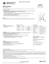 Swidget WI000UWA WiFi Control Module User manual
-
-
ATEN PE6208AV User manual
-
Inter-Tech SM-1688 Datasheet

