Page is loading ...

Betapack 4 User Manual v1 9850-000753-00 Page 1 of 12
USER MANUAL
Betapack 4
This product must be earthed
Apparatets stikprop skal tilsluttes en stikkontakt med jord, som giver forbindelse til stikproppens jord.
Laite on liitettävä suojakoskettimilla varustettuun pistorasiaan
Apparatet må tilkoples jordet stikkontakt
Apparaten skall anslutas till jordat uttag
This equipment is designed for professional stage
lighting control and is unsuitable for any other purpose. It
should be used by, or under the supervision of, an
appropriately qualified or trained person.
E&OE. Cooper Lighting Solutions reserves the right to
make changes to the equipment and specification
described in this manual without prior notice.
© Cooper Lighting Solutions UK Ltd

Betapack 4 User Manual v1 9850-000753-00 Page 2 of 12
Contents
Introduction ...................................................... 3
Thank you! ...................................................................... 3
To remove the cover ........................................ 3
Connecting the mains ...................................... 4
Three phase ................................................................... 4
Single phase ................................................................... 4
Three phase delta .......................................................... 4
Mounting / Installation ..................................... 5
In a 19" Rack .................................................................. 5
On a wall ......................................................................... 5
For Portable Use ............................................................ 5
Ventilation ....................................................................... 5
Configuration & settings ................................. 6
Introduction ..................................................................... 6
Control interface ............................................................. 6
Mode button ................................................................ 6
Enter button ................................................................ 6
Up & Down Buttons .................................................... 6
Default mode .................................................................. 6
Channel test ................................................................... 6
Setup modes .................................................................. 6
Manual control ............................................................ 6
DMX Address ............................................................. 7
DMX Fail ..................................................................... 7
Memories .................................................................... 7
Sequences ................................................................. 7
Preheat ....................................................................... 8
Topset ........................................................................ 8
Dimmer laws ............................................................... 8
Super user .......................................................................9
Lock/Unlock ................................................................ 9
Resetting Betapack 4 ................................................. 9
Firmware Version ....................................................... 9
Internal Temperature .................................................. 9
RDM Enable/Disable .................................................. 9
Electrical ......................................................... 10
Portable Appliance Testing ...................................... 10
DMX Connections .................................................... 10
DMX indication ......................................................... 10
RDM support ............................................................ 10
Mechanical ..................................................... 11
Cooling ........................................................... 11
Troubleshooting............................................. 12
Reporting a problem ...................................... 12
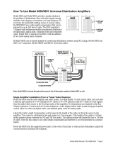
User interface
MCBs
DMX in
DMX thru
(auto terminating)
Hot power
sockets
Dim sockets
Up / Down
Mode
Enter
Labels

Betapack 4 User Manual v1 9850-000753-00 Page 3 of 12
Introduction
Thank you!
Thank you for choosing Betapack 4 by Zero 88 to fulfil your
lighting power needs. We sincerely hope that your new unit
will bring you years of trouble free service. We make great
efforts to build in reliability and serviceability at every stage
of our development and production processes and include
a three-year limited warranty - giving you peace of mind for
your investment.
Our extensive dealer network can also provide you with
technical service and sales support in your local language
no matter where you are in the world. If you have any
questions, comments or problems our contact details can
be found at zero88.com/support
Once again, thank you for choosing Zero 88.
To remove the cover
Isolate and disconnect Betapack 4 from the mains supply.
The mains supply terminals (and output terminals on the
hardwire version) are located under the top cover. To
remove the top cover, remove the four screws “A” in
Diagram 5 from the side plates.
The Triacs (type BTA40-600A/B) are located under the
bottom cover. To remove the bottom cover, remove the
four screws “B” in Diagram 5 from the side plates.
.
Diagram 1
WARNING!
Do not remove the covers without first completely disconnecting Betapack 4 from the mains supply

Betapack 4 User Manual v1 9850-000753-00 Page 4 of 12
Connecting the mains
A separate isolator and secure mains earth
connection are required.
Phase to Neutral voltage must not exceed 255VAC.
All wiring entering Betapack 4 must be rated to
+85ºC, H07RN-F cable is recommended.
Cut outs are provided on the ends and rear for
PG21 glands; one is supplied.
Supply terminals will accept wire sizes between
1.5mm
2
and 16mm
2
. Tightening torque is between
1.2Nm and 2.4Nm.
Hardwire Live/Neutral output terminals will accept
wire sizes up to 6mm
2
.
Hardwire Earth output ring-tags (blue crimp) will
accept wire sizes between 1.0mm
2
and 2.5mm
2
.
These may be replaced if larger diameter wiring is
installed.
Three phase
Betapack 4 is supplied configured for three-phase star
operation as shown in Diagram 2:
Diagram 2
Single phase
For single-phase operation, fit the supplied linking bar
between the L1, L2 and L3 terminals as shown in
Diagram 3:
Diagram 3
Three phase delta
For three-phase delta operation, the 6 neutral wires
must be removed from the terminal block, and the
crimped ferrules must be cut off. Strip the ends of these
6 wires, and reconnect as shown in Diagram 4:
Diagram 4

Betapack 4 User Manual v1 9850-000753-00 Page 5 of 12
Mounting / Installation
In a 19" Rack
Betapack 4 is supplied with side brackets fitted for rack
mounting.
On a wall
Undo the four screws ‘X’ to remove the brackets, replace
the screws in the holes for future use. Stand Betapack 4
on one end. Remove the two screws ‘Y’ (see Diagram
5), fit the brackets as shown and replace screws ‘Y’. Fit
the other bracket on the other end.
The wall drilling positions are shown in Diagram 6.
WARNING Completely fit one bracket at a time.
Removal of all four screws ‘Y’ at the same time can
allow the heatsink assembly to fall out! Allow a minimum
vertical spacing of 130mm between packs, and between
packs and other equipment. A spacing of 180mm is
recommended for ease of wiring and servicing.
For Portable Use
The ‘Easicarry’ Kit, consisting of a handle and four feet,
is included with Betapack 4. To fit, remove the brackets.
Fit the handle using the screws supplied and holes ‘Z’.
Fit the four feet to the other end using the holes ‘X’ and
‘Y’. See Diagram 5.
Ventilation
Betapack 4 is convection cooled with air flowing over the
rear mounted heatsink.
Diagram 5
Diagram 6
WARNING!
Betapack 4 is designed for indoor use only.
When one or more Betapack 4 units are mounted in an
enclosed rack, a fan MUST be fitted to ensure that adequate
cool air is circulated. Up to three Betapack 4s may be stacked
in free air.

Betapack 4 User Manual v1 9850-000753-00 Page 6 of 12
Configuration & settings
Introduction
Betapack 4 distributes both dimming and “hot power” to
a mixed rig of both tungsten and LED fixtures. Each of
the six channels are capable of driving up to 10Amp
loads.
Betapack 4 features MCBs as standard. When dimming,
there are preheat, topset and 3 laws per channel, 12
memories, 3 99-step sequences, local control and DMX
patch per channel.
An isolated DMX512-A input and loop-through allow for
remote operation. When the loop-through plug is not
inserted, the DMX line is automatically terminated.
The DMX control port supports RDM (Remote Device
Management) functionality.
Control interface
The main display consists of four seven-segment
displays; the data displayed is dependent on the set-up
mode of Betapack 4. Around the outside of these
displays are eight red LEDs which indicate the current
set-up mode of Betapack 4. An additional green LED is
used for DMX indication.
Betapack 4 has a default mode for operation. In this
mode none of the set-up mode LEDs will be lit, and the
main display will show the DMX address(es).
Mode button
The Mode button is used to cycle through the different
set-up modes. They are;
- Manual control
- DMX address
- DMX fail
- Memory
- Sequence
- Preheat
- Topset
- Law
Enter button
The Enter button is used to confirm actions.
Up & Down Buttons
These are used to adjust the values shown in the main
display. Pressing both buttons together will reset the
display to the default values.
Default mode
If a block patch has been set (see ‘DMX Address’
below), then the display will show the DMX start address
of the block.
If individual DMX addresses have been set for each
channel, then the ‘Up & Down’ Arrows can be used to
select which DMX address to display, or alternatively if
‘Auto’ is selected, then the display will cycle through all
six DMX addresses. In either case, the DMX address is
prefixed by the channel number.
Holding down the ‘Enter’ button in default mode will
change the display to ‘Out’, and the top 6 setup LEDs
(numbered) will change to displaying an indication of the
current output levels. Each LED will be lit if the current
output level for that channel is greater than 20%.
Channel test
While keeping the ‘Enter’ button held down in Default
Mode, use the ‘Up & Down’ Arrows to set a level of
100% on a single channel. Release the ‘Enter’ button to
remove this level.
Setup modes
Manual control
The Manual Control Mode allows you to set-up a look on
Betapack 4 without using an external controller.
Select ‘Manual’ mode using the ‘Mode’ button. The
display will show C.LLL, where C is the channel number
and LLL is the level. Select the channel you require or
‘A’ for all channels, using the ‘Up & Down’ Arrows and
press ‘Enter’. Now set the level you require using the
‘Up & Down’ Arrows and press ‘Enter’ again to confirm
and move back to the channel selection.
The Manual Control levels are reset to zero if power to
Betapack 4 is lost.
WARNING!
Configuration & settings affect the “Dim” sockets only. The
“hot power” sockets will be unaffected by these settings.

Betapack 4 User Manual v1 9850-000753-00 Page 7 of 12
DMX Address
There are 2 ways that Betapack 4 can be patched – a
single DMX start address can be set for the block of 6
channels (block patch), or each channel can be given a
different DMX start address.
For block patch, the range of DMX start addresses is
001 – 507. For individual patch, the range of DMX start
addresses is 001 – 512
Select ‘DMX ADR’ using the ‘Mode’ button, the display
will show C.AAA, where C is the channel number and
AAA is the current DMX address for that channel. Select
the channel you require (1-6), or ‘A’ for all channels
(block patch), using the ‘Up & Down’ Arrows and press
‘Enter’. Now set the address you require using the ‘Up &
Down’ Arrows and press ‘Enter’ again to confirm and
move back to the channel selection.
DMX Fail
There are four DMX fail modes available – ‘hold DMX’,
‘fade to black’, ‘fade to memory’ and ‘fade to sequence’.
Select ‘DMX Fail’ using the ‘Mode’ button. Using the ‘Up
& Down’ Arrows select your preferred choice from the
list below;
Fail Mode
Main Display
Hold Last State
Hold
Fade to Zero
F 00
Fade to Memory 1 - 12
F 01 – F 12
Fade to Sequence 1 - 3
S 01 – S 03
If there is no DMX present, the selected
memory/sequence will be re-called immediately.
Memories
Betapack 4 will store 12 memories for standalone
operation, these can only be re-called if there is no DMX
present.
1. Set-up the scene using the ‘Manual’ control function
or a DMX controller.
2. Select ‘Memory’ using the ‘Mode’ button.
Using the ‘Up & Down’ Arrows select the required
memory number and press the ‘Enter’ button to confirm.
A ‘p’ should appear next to the memory to signify that it
has been programmed.
Holding both the ‘Up & Down’ Arrows for 1 second will
clear the selected memory. If these buttons are held for
5 seconds, ALL memories will be cleared.
If memories are cleared which are used in sequences,
they will be removed automatically from those
sequences.
Sequences
Betapack 4 will store 3 sequences of up to 99-steps
each. Each step is a link to one of the 12 programmed
memories. Sequences can only be replayed if there is
no DMX present.
Each sequence can have a fade time (0-60s) and dwell
time (1-60s) programmed. It is only possible to add
steps to or remove steps from the end of a sequence.
1. Program the required looks using the ‘Memories’
function (see above).
2. Select ‘Sequence’ using the ‘Mode’ button.
3. Use the ‘Up & Down’ Arrows to select the required
sequence (the number of steps already
programmed in each sequence is shown after the
sequence number on the display) and press the
‘Enter’ button to confirm.
4. The display will now change to show the current
step number, followed by the memory currently
programmed in that step. Use the ‘Up & Down’
Arrows to select the required step number (or Fade
time ‘F’ or dwell time ‘d’) and press the ‘Enter’
button to confirm.
5.
a. For steps: If there is no DMX present, the
selected memory will be immediately re-called.
Use the ‘Up & Down’ Arrows to select the
memory for that step and press the ‘Enter’
button to confirm. Only programmed memories
may be selected. If the step is at the end of the
sequence, then the step number will
automatically increment, and further steps may
now be programmed in the same way.
Otherwise the display will return to step
number selection mode.
b. For fade and dwell times: If there is no DMX
present, the sequence will now run. Use the
‘Up & Down’ Arrows to change the time and
press the ‘Enter’ button to confirm.
When done, or to return to sequence selection mode
(step 3 above) at any point, press and hold the ‘Enter’
button for 1s.
At step 3 above, holding both the ‘Up & Down’ Arrows
for 1 second will clear the selected sequence. If these
buttons are held for 5 seconds, ALL sequences will be
cleared.

Betapack 4 User Manual v1 9850-000753-00 Page 8 of 12
At step 5 above, if the selected step is at the end of the
sequence, holding both the ‘Up & Down’ Arrows will
clear the selected step.
Preheat
Preheat can be selected on a per channel or all channel
basis. The preheat level is 5% and cannot be adjusted.
Select ‘Preheat’ by cycling through the modes using the
‘Mode’ button.
Select required channel or ‘A’ for all channels, using the
‘Up & Down’ Arrows and press ‘Enter’, to confirm.
Now select on/off using the ‘Up & Down’ Arrows. Press
‘Enter’ to confirm and return to the channel selection.
Note that Preheat is only applied if there is a DMX input
present, and the law is not set to ‘Switch’.
Topset
Topset can be selected on a per channel or all channel
basis. On Betapack 4, Topset is applied as a limiting
(not scaling) value.
Select ‘Topset’ by cycling through the modes using the
‘Mode’ button.
Select required channel or ‘A’ for all channels, using the
‘Up & Down’ Arrows and press ‘Enter’, to confirm.
Now select the topset level you require, again using the
‘Up & Down’ Arrows and press ‘Enter’ to confirm and
return to the channel selection.
Note that if the law is set to ‘Switch’, the setting in
Topset will instead be used to determine the switchpoint.
The ‘Topset’ LED will flash in this case, to indicate the
setting being made.
Dimmer laws
Three dimmer laws are available, which can be selected
per channel.
Select ‘Law’ mode using the ‘Mode’ button. Using the
‘Up & Down’ Arrows select the channel required, or ‘A’
for all channels. Press ‘Enter’ to confirm. Now select the
law you require, again using the ‘Up & Down’ Arrows
and press ‘Enter’ to confirm and return to the channel
selection.
Output Law
Main Display
Normal
n
Switch
S
Linear
L
Note that if the law is set to Switch, the switchpoint can
be set in the ‘Topset’ menu.

Betapack 4 User Manual v1 9850-000753-00 Page 9 of 12
Super user
Betapack 4 has a number of hidden functions, located in
the Super User Menu. The super user menus can only
be accessed from the Default mode (no LEDs lit). To
enter Super User press and hold the ‘Up & Down’
Arrows together and press and hold the ‘Mode’ button
for 5 seconds. All the mode LEDs will flash to indicate
Betapack 4 is in super user mode.
The ‘Up & Down’ Arrows are used to cycle through the
various super user functions. Pressing the ‘Mode’ button
at any point will revert to normal operation. If no buttons
are pressed after 20 seconds the unit will automatically
revert to normal operation.
Lock/Unlock
Press the ‘Up & Down’ Arrows until the display shows
“LOC”. Press ‘Enter’ to confirm this action. Betapack 4
will revert to the Default mode. Pressing the ‘Mode’
button now will only cycle between Manual Control and
Default Mode.
If Super User is entered when Betapack 4 is locked, only
the unlock function will be available. The display will
show “UNL”. To unlock Betapack 4, press and hold the
‘Enter’ button for 5 seconds. Betapack 4 will unlock and
exit super user returning to the Default mode.
Resetting Betapack 4
Press the ‘Up & Down’ Arrows until the display shows
“rset”. Press ‘Enter’ to confirm. The display will flash
briefly to confirm this action. Betapack 4 will be reset to
its default settings, shown in the table below:
Set Up Parameter
State
Manual Control Levels
All Off
DMX Addresses
Block patch at 001
DMX Fail Mode
Hold Last State
Memory
All Memories Cleared
Sequence
All Sequences Cleared
Preheat
Off (0%) for all channels
Topset
100% for all channels
Law
Normal law for all channels
Switch law switch point
50% for all channels
RDM
Enabled
Firmware Version
To identify which version of firmware is loaded in
Betapack 4, press the ‘Up & Down’ Arrows until the
firmware version is shown in the display (e.g. 02.00)
Press and hold the ‘Enter’ button for 1s, and Betapack
4’s CPU serial number will be displayed. Press the
‘Enter’ button again to return to the version display. Note
that the firmware version will also be shown briefly on
start up.
Internal Temperature
Press the ‘Up & Down’ Arrows until the temperature is
shown in the display, shown as xxxC, where xxx is the
temperature in Centigrade. The ‘Enter’ button has no
function in this mode.
RDM Enable/Disable
To enable or disable RDM (Remote Device
Management) functionality on the DMX control port,
press the ‘Up & Down’ Arrows until “ron” or “rof” is
displayed. The ‘Enter’ button toggles this setting
between “ron” (RDM enable) and” rof” (RDM disabled).

Betapack 4 User Manual v1 9850-000753-00 Page 10 of 12
Electrical
Betapack 4 is designed to operate on 230VAC +10% -
15% at 50-60Hz (auto sensing). The pack may not
operate satisfactorily outside this specification.
The packs may be wired:
- Single Phase: 60A 1 phase 2-wire 230V
(255V max phase to neutral)
Earth leakage less than 1mA
- Three Phase Star: 20A 4-wire 230/380V
(255V max phase to neutral)
Earth leakage less than 1mA
- Three Phase Delta: 30A 3-wire 230V
(255V max phase to phase)
Earth leakage less than 4mA
Max total load: 13.9kW @ 230V
Load per channel: 0.1A Min; 10A Max
No load consumption: 10W
Rise Time: 80uS
Triac Type: BTA40-600A/B
If used in conjunction with MCBs, to avoid nuisance
tripping use high inrush current (Type K) MCBs.
The “dim” sockets allow for lighting loads which are
resistive or inductive, including tungsten, transformer
driven low voltage (e.g. pinspots), and quartz halogen.
Electronic transformers plugged into the “dim” socket
must be suitable for leading edge dimming.
Portable Appliance Testing
DMX Connections
Conforms to USITT DMX512-A (isolated).
One male and one female 5 pin XLR connector. DMX
line is automatically terminated when the loop-through
plug is not inserted. The pin assignment is:
Pin 1 0V
Pin 2 DMX- (RS485 B line)
Pin 3 DMX+ (RS485 A line)
Pin 4 Reserved
Pin 5 Reserved
DMX indication
Status
Description
On
DMX data (start byte of 00) being
received OK.
Flash Fast
Data being received, but not DMX data
(start byte of 00)
Flash Slow
DMX data errors occurring.
Off
No DMX data being received.
RDM support
Protocol Version
1.0
Device Model ID
307 (0x0133)
Supported
Parameters
DMX_START_ADDRESS,
SENSOR_DEFINITION,
SENSOR_VALUE,
DEVICE_LABEL,
MANUFACTURER_LABEL,
DEVICE_MODEL_DESCRIPTION
Sub Devices
6 (one per channel)
WARNING!
Do not remove the covers without first completely
disconnecting Betapack 4 from the mains supply
WARNING!
Betapack 4 will fail the portable appliance high voltage test
as it has capacitors connected between Live 1/2/3 and Earth,
and between Neutral and Earth, to enable it to comply with
CE regulations.

Betapack 4 User Manual v1 9850-000753-00 Page 11 of 12
Mechanical
- Height: 175mm
- Width: 440mm
- Depth: 195mm
- Weight: 8.0kg (17.6lb)
- IP Rating: IP2X (indoor use only)
Cooling
Ambient Temperature: +5ºC to +40ºC.
Relative Humidity: 5% to 95% non-condensing.
Betapack 4 is convection cooled and includes a
temperature sensor which monitors the internal
temperature. If the temperature rises above the normal
operating level the outputs are first reduced, then
switched off altogether until the temperature falls back to
a safe level.
The table below shows how Betapack 4 will react under
these conditions. (Note: The temperature shown on the
display will be the actual temperature not the rounded
figures given below).
Temperature
Output Levels
(% of control)
Main display
<75ºC
100%
normal
75ºC→80ºC
100%
“075c”
80ºC→85ºC
80%
“080c”
85ºC→90ºC
60%
“085c”
90ºC→95ºC
40%
“090c”
>95ºC
0%
“hot”
sensor fault
100%
“err”
Compliance & Standards
Betapack 4 complies with the following standards:
EN 55015:2013 + A1:2015
Limits and methods of measurement of radio
disturbance characteristics of electrical lighting and
similar equipment
EN 61547:2009
Equipment for general lighting purposes - EMC Immunity
requirements
EN 61439-1:2011
Low-voltage switchgear and controlgear assemblies.
Part 1: General Rules
EN 61439-2:2011
Low-voltage switchgear and controlgear assemblies.
Part 2: Power switchgear and controlgear assemblies
EN 50581:2012
Assessment of products with respect to RoHS II

Betapack 4 User Manual v1 9850-000753-00 Page 12 of 12
Troubleshooting
If you are experiencing problems with Betapack 4,
please check the list below for common causes and
solutions.
If you are unsure how to make any of the checks, please
contact Zero 88 technical support for advice or assistance.
Symptoms
Solutions
Betapack 4 does not power up when
power is applied.
1. Check there is a mains voltage on the incoming supply terminal.
2. Check the incoming supply terminals are all adequately tightened.
3. Check the link cable between the control PCB on the front panel and the
power PCB has not been disconnected or damaged.
Betapack 4 is powering up but some
or all of the channels are either not
working or will not go to full output.
1. Check the channel breakers are in the ‘on’ position.
2. Check the channels have not had a Topset applied to them. Please see
“Topset” for further details.
3. If Betapack 4 is wired single phase check that the single-phase link bar
has been fitted. If it is fitted check the screws are adequately tightened.
Please see “diagram 3” for further details.
Channels will switch on and off but are
not able to be dimmed.
1. The channel law has been set to switch. Please see “Dimmer Laws” for
further information.
The display is outputting a sequence
of numbers after the Betapack 4 has
been powered up.
1. Channels have been soft patched.
2. Please see “DMX Address” for further details.
Unable to access any of the Betapack
4 functions.
1. Betapack 4 has been locked.
2. Please see “Lock/Unlock” for further details.
Channel is remaining on all the time,
even after disconnecting the controller
and power cycling the Betapack 4.
1. Triac has failed. Please contact your local service centre or contact Zero
88 technical support for further information
Reporting a problem
Support requests can be submitted through our support
forum at zero88.com/forum or via email to
support@zero88.com
For more urgent requests, please contact Zero 88 by
telephone on +44 (0)1633 838088 – 24 hour answer
service available.
If you have reported a problem by email or on the forum,
please bear with us as our response may take a few
days if your problem is complex. It is also worth
checking other posts on the forum to see if the fault is
already reported / fixed before contacting Zero 88.
WARNING!
These checks should ONLY be carried out by a qualified
electrician
/