Page is loading ...

VictorThermalDynamics.com
120
208-
230V
460V
Art # A-08619_AC
600V
Operating
Manual
Revision: AN Issue Date: Februrary 11, 2014 Manual No.: 0-4987
CUTMASTER
™
152
PLASMA CUTTING SYSTEM

!
WARNING
Read and understand this entire Manual and your employer’s safety practices before installing, operat-
ing, or servicing the equipment.
While the information contained in this Manual represents the Manufacturer's best judgement, the
Manufacturer assumes no liability for its use.
Plasma Cutting Power Supply
CutMaster™ 152
SL100 1Torch™
Operating Manual Number 0-4987
Published by:
Victor Technologies International, Inc.
82 Benning Street
West Lebanon, New Hampshire, USA 03784
(603) 298-5711
www.victorthermaldynamics.com
Copyright 2008, 2009, 2010, 2012, 2013 by
Victor Technologies International, Inc.
All rights reserved.
Reproduction of this work, in whole or in part, without written permission of the
publisher is prohibited.
The publisher does not assume and hereby disclaims any liability to any party for any
loss or damage caused by any error or omission in this Manual, whether such error
results from negligence, accident, or any other cause.
Original Publication Date: May 30, 2008
Revision Date: February 11, 2014
Record the following information for Warranty purposes:
Where Purchased:_______________________________ ________________
Purchase Date:__________________________________ ________________
Power Supply Serial #:___________________________ ________________
Torch Serial #:___________________________________ ________________
i
WE APPRECIATE YOUR BUSINESS!
Congratulations on your new Victor Thermal Dynamics product. We are proud to have you as our
customer and will strive to provide you with the best service and reliability in the industry. This product
is backed by our extensive warranty and world-wide service network. To locate your nearest distributor
or service agency call 1-800-426-1888, or visit us on the web at www.VictorThermalDynamics.com.
This Operating Manual has been designed to instruct you on the correct use and operation of your
Victor Thermal Dynamics product. Your satisfaction with this product and its safe operation is our
ultimate concern. Therefore please take the time to read the entire manual, especially the Safety Pre-
cautions. They will help you to avoid potential hazards that may exist when working with this product.
YOU ARE IN GOOD COMPANY!
The Brand of Choice for Contractors and Fabricators Worldwide.
Victor Thermal Dynamics is a Global Brand of manual and automation Plasma Cutting Products for
Victor Technologies.
We distinguish ourselves from our competition through market-leading, dependable products that
have stood the test of time. We pride ourselves on technical innovation, competitive prices, excel-
lent delivery, superior customer service and technical support, together with excellence in sales and
marketing expertise.
Above all, we are committed to developing technologically advanced products to achieve a safer
working environment within the welding industry.

This Page Intentionally Blank

TABLE OF CONTENTS
SECTION 1: GENERAL INFORMATION ...............................................................................1-1
1.01 Notes, Cautions and Warnings ...................................................................1-1
1.02 Important Safety Precautions .....................................................................1-1
1.03 Publications ................................................................................................1-2
1.04 Note, Attention et Avertissement ................................................................1-3
1.05 Precautions De Securite Importantes .........................................................1-3
1.06 Documents De Reference ..........................................................................1-5
1.07 Declaration of Conformity ...........................................................................1-6
1.08 Statement of Warranty ................................................................................ 1-7
SECTION 2 SYSTEM: INTRODUCTION ...............................................................................2-1
2.01 How To Use This Manual ...........................................................................2-1
2.02 Equipment Identification .............................................................................2-1
2.03 Receipt Of Equipment .................................................................................2-1
2.04 Power Supply Specifications ......................................................................2-2
2.05 Input Wiring Specifications .........................................................................2-3
2.06 Power Supply Features ..............................................................................2-4
SECTION 2 TORCH: INTRODUCTION ...............................................................................2T-1
2T.01 Scope of Manual .......................................................................................2T-1
2T.02 General Description ..................................................................................2T-1
2T.03 Specifications ...........................................................................................2T-1
2T.04 Options And Accessories ..........................................................................2T-2
2T.05 Introduction to Plasma ..............................................................................2T-2
SECTION 3 SYSTEM: INSTALLATION ................................................................................3-1
3.01 Unpacking ................................................................................................... 3-1
3.02 Lifting Options ............................................................................................. 3-1
3.03 Opening the Contactor Cover .....................................................................3-1
3.04 Primary Input Power Connections ..............................................................3-1
3.05 Gas Connections ........................................................................................3-3
SECTION 3 TORCH: INSTALLATION .................................................................................3T-1
3T.01 Torch Connections ....................................................................................3T-1
3T.02 Setting Up Mechanical Torch ....................................................................3T-1
SECTION 4 SYSTEM: OPERATION ......................................................................................4-1
4.01 Front Panel Controls / Features ..................................................................4-1
4.02 Preparations for Operation .........................................................................4-2
SECTION 4 TORCH: OPERATION ......................................................................................4T-1
4T.01 Torch Parts Selection ...............................................................................4T-1
4T.02 Cut Quality ................................................................................................4T-2
4T.03 General Cutting Information ......................................................................4T-2
4T.04 Hand Torch Operation ..............................................................................4T-3
4T.05 Gouging ....................................................................................................4T-6
4T.06 Mechanized Torch Operation ...................................................................4T-7
4T.07 Parts Selection for SL100 Torch Cutting ..................................................4T-9
4T.08 Recommended Cutting Speeds for SL100 Torch With Exposed Tip ......4T-10
4T.09 Recommended Cutting Speeds for SL100 Torch With Shielded Tip ......4T-15

TABLE OF CONTENTS
PATENT INFORMATION .....................................................................................................4T-20
SECTION 5 SYSTEM: SERVICE ............................................................................................ 5-1
5.01 General Maintenance .................................................................................5-1
5.02 Maintenance Schedule ...............................................................................5-2
5.03 Common Faults ..........................................................................................5-2
5.04 Fault Indicator .............................................................................................5-3
5.05 Basic Troubleshooting Guide ......................................................................5-4
5.06 Power Supply Basic Parts Replacement ....................................................5-6
SECTION 5 TORCH: SERVICE ............................................................................................5T-1
5T.01 General Maintenance ...............................................................................5T-1
5T.02 Inspection and Replacement of Consumable Torch Parts .......................5T-2
SECTION 6: PARTS LISTS ....................................................................................................6-1
6.01 Introduction .................................................................................................6-1
6.02 Ordering Information ................................................................................... 6-1
6.03 Power Supply Replacement .......................................................................6-1
6.04 Replacement Power Supply Parts ..............................................................6-2
6.05 Options and Accessories ............................................................................6-2
6.06 Replacement Parts for Hand Torch ...........................................................6-3
6.07 Replacement Parts - for Machine Torches with Unshielded Leads ............6-4
6.08 Replacement Shielded Machine Torch Leads Assemblies ........................6-6
6.09 Torch Consumable Parts (SL100) ..............................................................6-7
APPENDIX 1: SEQUENCE OF OPERATION (BLOCK DIAGRAM) ..................................... A-1
APPENDIX 2: DATA TAG INFORMATION ............................................................................ A-2
APPENDIX 3: TORCH PIN - OUT DIAGRAMS ...................................................................... A-3
APPENDIX 4: TORCH CONNECTION DIAGRAMS .............................................................. A-4
APPENDIX 5: SYSTEM SCHEMATIC, 208/460V UNITS ....................................................... A-6
APPENDIX 6: SYSTEM SCHEMATIC, 600V UNITS .............................................................. A-8
APPENDIX 7: PUBLICATION HISTORY ............................................................................. A-10
GLOBAL CUSTOMER SERVICE CONTACT INFORMATION ............................ REAR COVER

CUTMASTER 152
Manual 0-4987 GENERAL INFORMATION
1-1
SECTION 1:
GENERAL INFORMATION
1.01 Notes, Cautions and Warnings
Throughout this manual, notes, cautions, and warnings
are used to highlight important information. These
highlights are categorized as follows:
NOTE
An operation, procedure, or background
information which requires additional em-
phasis or is helpful in efficient operation of
the system.
CAUTION
A procedure which, if not properly followed,
may cause damage to the equipment.
!
WARNING
A procedure which, if not properly followed,
may cause injury to the operator or others in
the operating area.
WARNING
Gives information regarding possible electri-
cal shock injury. Warnings will be enclosed
in a box such as this.
1.02 Important Safety Precautions
!
WARNING
OPERATION AND MAINTENANCE OF
PLASMA ARC EQUIPMENT CAN BE DAN-
GEROUS AND HAZARDOUS TO YOUR
HEALTH.
Plasma arc cutting produces intense electric
and magnetic emissions that may interfere
with the proper function of cardiac pacemak-
ers, hearing aids, or other electronic health
equipment. Persons who work near plasma
arc cutting applications should consult their
medical health professional and the manufac-
turer of the health equipment to determine
whether a hazard exists.
To prevent possible injury, read, understand
and follow all warnings, safety precautions
and instructions before using the equipment.
Call 1-603-298-5711 or your local distributor
if you have any questions.
GASES AND FUMES
Gases and fumes produced during the plasma cutting
process can be dangerous and hazardous to your health.
• Keepallfumesandgasesfromthebreathingarea.
Keepyourheadoutoftheweldingfumeplume.
• Useanair-suppliedrespiratorifventilationisnot
adequate to remove all fumes and gases.
• Thekindsoffumesandgasesfromtheplasmaarc
depend on the kind of metal being used, coatings
on the metal, and the different processes. You must
be very careful when cutting or welding any metals
which may contain one or more of the following:
Antimony Chromium Mercury
Arsenic Cobalt Nickel
Barium Copper Selenium
Beryllium Lead Silver
Cadmium Manganese Vanadium
• AlwaysreadtheMaterialSafetyDataSheets
(MSDS) that should be supplied with the material
you are using. These MSDSs will give you the in-
formation regarding the kind and amount of fumes
and gases that may be dangerous to your health.
• Forinformationonhowtotestforfumesandgases
in your workplace, refer to item 1 in Subsection
1.03, Publications in this manual.
• Usespecialequipment,suchaswaterordowndraft
cutting tables, to capture fumes and gases.
• Donotusetheplasmatorchinanareawherecom-
bustible or explosive gases or materials are located.
• Phosgene,atoxicgas,isgeneratedfromthevapors
of chlorinated solvents and cleansers. Remove all
sources of these vapors.
• WARNING: This product contains chemicals,
including lead, known to the State of California to
cause birth defects and other reproductive harm.
Wash hands after handling.
ELECTRIC SHOCK
Electric Shock can injure or kill. The plasma arc process
uses and produces high voltage electrical energy. This
electric energy can cause severe or fatal shock to the
operator or others in the workplace.
• Nevertouchanypartsthatareelectrically“live”
or“hot.”

CUTMASTER 152
Manuel 0-4987 INFORMATIONS GÉNÉRALES
1-3
CUTMASTER 152
GENERAL INFORMATION Manual 0-4987
1-2
4. ANSI Standard Z87.1, SAFE PRACTICES FOR OC-
CUPATION AND EDUCATIONAL EYE AND FACE
PROTECTION, obtainable from American National
Standards Institute, 1430 Broadway, New York, NY
10018
5. ANSI Standard Z41.1, STANDARD FOR MEN’S SAFE-
TY-TOE FOOTWEAR, obtainable from the American
National Standards Institute, 1430 Broadway, New
York, NY 10018
6. ANSI Standard Z49.2, FIRE PREVENTION IN THE USE
OF CUTTING AND WELDING PROCESSES, obtain-
able from American National Standards Institute, 1430
Broadway, New York, NY 10018
7. AWS Standard A6.0, WELDING AND CUTTING CON-
TAINERS WHICH HAVE HELD COMBUSTIBLES,
obtainable from American Welding Society, 550 N.W.
LeJeune Rd, Miami, FL 33126
8. NFPA Standard 51, OXYGEN-FUEL GAS SYSTEMS
FOR WELDING, CUTTING AND ALLIED PRO-
CESSES, obtainable from the National Fire Protection
Association, Batterymarch Park, Quincy, MA 02269
9. NFPA Standard 70, NATIONAL ELECTRICAL CODE,
obtainable from the National Fire Protection Associa-
tion, Batterymarch Park, Quincy, MA 02269
10. NFPA Standard 51B, CUTTING AND WELDING PRO-
CESSES, obtainable from the National Fire Protection
Association, Batterymarch Park, Quincy, MA 02269
11. CGA Pamphlet P-1, SAFE HANDLING OF COM-
PRESSED GASES IN CYLINDERS, obtainable from
the Compressed Gas Association, 1235 Jefferson Davis
Highway, Suite 501, Arlington, VA 22202
12. CSA Standard W117.2, CODE FOR SAFETY IN WELD-
ING AND CUTTING, obtainable from the Canadian
Standards Association, Standards Sales, 178 Rexdale
Boulevard, Rexdale, Ontario, Canada M9W 1R3
13. NWSA booklet, WELDING SAFETY BIBLIOGRAPHY
obtainable from the National Welding Supply Associa-
tion, 1900 Arch Street, Philadelphia, PA 19103
14. American Welding Society Standard AWSF4.1, REC-
OMMENDED SAFE PRACTICES FOR THE PREPARA-
TION FOR WELDING AND CUTTING OF CONTAIN-
ERS AND PIPING THAT HAVE HELD HAZARDOUS
SUBSTANCES, obtainable from the American Welding
Society, 550 N.W. LeJeune Rd, Miami, FL 33126
15. ANSI Standard Z88.2, PRACTICE FOR RESPIRATORY
PROTECTION, obtainable from American National
Standards Institute, 1430 Broadway, New York, NY
10018
1.04 Note, Attention et Avertissement
Danscemanuel,lesmots“note,”“attention,”et“aver-
tissement”sontutiliséspourmettreenreliefdesinfor-
mations à caractère important. Ces mises en relief sont
classiéescommesuit:
NOTE
Touteopération,procédureourenseigne-
mentgénéralsurlequelilimported’insister
davantageouquicontribueàl’efcacitéde
fonctionnement du système.
• Weardryglovesandclothing.Insulateyourself
from the work piece or other parts of the welding
circuit.
• Repairorreplaceallwornordamagedparts.
• Extracaremustbetakenwhentheworkplaceis
moist or damp.
• InstallandmaintainequipmentaccordingtoNEC
code, refer to item 9 in Subsection 1.03, Publica-
tions.
• Disconnectpowersourcebeforeperformingany
service or repairs.
• ReadandfollowalltheinstructionsintheOperat-
ing Manual.
FIRE AND EXPLOSION
Fire and explosion can be caused by hot slag, sparks, or
the plasma arc.
• Besurethereisnocombustibleorammablemate-
rial in the workplace. Any material that cannot be
removed must be protected.
• Ventilateallammableorexplosivevaporsfrom
the workplace.
• Donotcutorweldoncontainersthatmayhave
held combustibles.
• Providearewatchwhenworkinginanarea
where fire hazards may exist.
• Hydrogengasmaybeformedandtrappedunder
aluminum workpieces when they are cut under-
water or while using a water table. DO NOT cut
aluminum alloys underwater or on a water table
unless the hydrogen gas can be eliminated or dis-
sipated. Trapped hydrogen gas that is ignited will
cause an explosion.
NOISE
Noise can cause permanent hearing loss. Plasma arc
processes can cause noise levels to exceed safe limits.
You must protect your ears from loud noise to prevent
permanent loss of hearing.
• Toprotectyourhearingfromloudnoise,wearpro-
tective ear plugs and/or ear muffs. Protect others
in the workplace.
• Noiselevelsshouldbemeasuredtobesurethe
decibels (sound) do not exceed safe levels.
• Forinformationonhowtotestfornoise,seeitem
1 in Subsection 1.03, Publications, in this manual.
PLASMA ARC RAYS
Plasma Arc Rays can injure your eyes and burn your
skin. The plasma arc process produces very bright ultra
violet and infra red light. These arc rays will damage
your eyes and burn your skin if you are not properly
protected.
• Toprotectyoureyes,alwayswearaweldinghel-
met or shield. Also always wear safety glasses
with side shields, goggles or other protective eye
wear.
• Wearweldingglovesandsuitableclothingto
protect your skin from the arc rays and sparks.
• Keephelmetandsafetyglassesingoodcondition.
Replace lenses when cracked, chipped or dirty.
• Protectothersintheworkareafromthearcrays.
Use protective booths, screens or shields.
• Usetheshadeoflensassuggestedinthefollowing
per ANSI/ASC Z49.1:
Minimum Protective Suggested
Arc Current Shade No. Shade No.
Less Than 300* 8 9
300 - 400* 9 12
400 - 800* 10 14
* These values apply where the actual arc
is clearly seen. Experience has shown that
lighter filters may be used when the arc is
hidden by the workpiece.
!
WARNING
WARNING: This product contains chemicals, includ-
ing lead, known to the State of California to cause birth
defects and other reproductive harm.
Wash hands after
handling.
1.03 Publications
Refer to the following standards or their latest revisions
for more information:
1. OSHA, SAFETY AND HEALTH STANDARDS, 29CFR
1910, obtainable from the Superintendent of Docu-
ments, U.S. Government Printing Office, Washington,
D.C. 20402
2. ANSI Standard Z49.1, SAFETY IN WELDING AND
CUTTING, obtainable from the American Welding
Society, 550 N.W. LeJeune Rd, Miami, FL 33126
3. NIOSH, SAFETY AND HEALTH IN ARC WELDING
AND GAS WELDING AND CUTTING, obtainable
from the Superintendent of Documents, U.S. Govern-
ment Printing Office, Washington, D.C. 20402
ATTENTION
Touteprocédurepouvantrésulterl’endom-
magementdumatérielencasdenon-respect
delaprocédureenquestion.
!
AVERTISSEMENT
Touteprocédurepouvantprovoquerdesbles-
suresdel’opérateuroudesautrespersonnes
se trouvant dans la zone de travail en cas de
non-respectdelaprocédureenquestion.
AVERTISSEMENT
Fournit l'information concernant des dom-
magespossiblesdechocélectrique. Des
avertissementsserontenfermésdansuneboîte
de ce type.
1.05 Precautions De Securite Importantes
!
AVERTISSEMENTS
L’OPÉRATION ET LA MAINTENANCE DU
MATÉRIEL DE SOUDAGE À L’ARC AU JET
DE PLASMA PEUVENT PRÉSENTER DES
RISQUES ET DES DANGERS DE SANTÉ.
Coupant à l’arc au jet de plasma produit
del’énergieélectriquehaute tensionetdes
émissionsmagnétiquequipeuventinterférer
lafonctionpropred’un“pacemaker”cardia-
que,lesappareilsauditif,ouautrematériel
desantéelectronique.Ceuxquitravailprès
d’une application à l’arc au jet de plasma
devrait consulter leur membre professionel de
médicationetlemanufacturierdematérielde
santépourdéterminers’ilexistedesrisques
desanté.
Ilfautcommuniquerauxopérateurset au
personnel TOUS les dangers possibles. Afin
d’éviterlesblessurespossibles,lisez,compre-
nez et suivez tous les avertissements, toutes les
précautionsdesécuritéettouteslesconsignes
avantd’utiliserlematériel.Composezle+
603-298-5711 ou votre distributeur local si vous
avez des questions.

CUTMASTER 152
INFORMATIONS GÉNÉRALES Manuel 0-4987
1-4
CUTMASTER 152
Manuel 0-4987 INFORMATIONS GÉNÉRALES
1-5
RAYONS D’ARC DE PLASMA
Les rayons provenant de l’arc de plasma peuvent bles-
servosyeuxetbrûlervotrepeau.Leprocédéàl’arcde
plasma produit une lumière infra-rouge et des rayons
ultra-violets très forts. Ces rayons d’arc nuiront à vos
yeuxetbrûlerontvotrepeausivousnevousprotégez
pas correctement.
• Pourprotégervosyeux,porteztoujoursuncasqueou
unécrandesoudeur.Porteztoujoursdeslunettesde
sécuritémuniesdeparoislatéralesoudeslunettesde
protection ou une autre sorte de protection oculaire.
• Portezdesgantsdesoudeuretunvêtementprotec-
teurappropriépourprotégervotrepeaucontreles
étincellesetlesrayonsdel’arc.
• Maintenezvotrecasqueetvoslunettesdeprotection
enbonétat.Remplaceztoutelentillesaleoucompor-
tant fissure ou rognure.
• Protégezlesautrespersonnessetrouvantsurlazone
de travail contre les rayons de l’arc en fournissant des
cabinesoudesécransdeprotection.
• Utilisezlanuancedelentillequiestsuggèréedansle
recommendation qui suivent ANSI/ASC Z49.1:
Nuance Minimum Nuance Suggerée
Courant Arc Protective Numéro Numéro
Moins de 300* 8 9
300 - 400* 9 12
400 - 800* 10 14
* Ces valeurs s’appliquent ou l’arc actuel est
observéclairement.L’experienceadémon-
trerquelesltresmoinsfoncéspeuventêtre
utilisésquandl’arcestcachéparmoiceaude
travail.
BRUIT
Le bruit peut provoquer une perte permanente de l’ouïe.
Lesprocédésdesoudageàl’arcdeplasmapeuvent
provoquerdesniveauxsonoressupérieursauxlimites
normalementacceptables.Vousdúezvousprotéger
lesoreillescontrelesbruitsfortsand’éviteruneperte
permanente de l’ouïe.
• Pourprotégervotreouïecontrelesbruitsforts,portez
des tampons protecteurs et/ou des protections auri-
culaires.Protégezégalementlesautrespersonnesse
trouvant sur le lieu de travail.
FUMÉE et GAZ
Lafuméeetlesgazproduitsparleprocédédejetde
plasmapeuventprésenterdesrisquesetdesdangers
desanté.
• Eloigneztoutefuméeetgazdevotrezonederespi-
ration.Gardezvotretêtehorsdelaplumedefumée
provenant du chalumeau.
• Utilisezunappareilrespiratoireàalimentationen
airsil’aérationfournienepermetpasd’éliminerla
fuméeetlesgaz.
• Lessortesdegazetdefuméeprovenantdel’arcde
plasmadépendentdugenredemétalutilisé,des
revêtementssetrouvantsurlemétaletdesdifférents
procédés.Vousdevezprendresoinlorsquevous
coupezousoudeztoutmétalpouvantcontenirun
ouplusieursdesélémentssuivants:
antimoine cadmium mercure
argent chrome nickel
arsenic cobalt plomb
baryum cuivre sélénium
béryllium manganèse vanadium
• Liseztoujoursleschesdedonnéessurlasécuritédes
matières(sigleaméricain“MSDS”);celles-cidevraient
êtrefourniesaveclematérielquevousutilisez.Les
MSDS contiennent des renseignements quant à la
quantitéetlanaturedelafuméeetdesgazpouvant
poserdesdangersdesanté.
• Pourdes informationssurlamanièredetesterla
fuméeetlesgazdevotrelieudetravail,consultez
l’article1etlesdocumentscitésàlapage5.
• Utilisezunéquipementspécialtelquedestablesde
coupeàdébitd’eauouàcourantdescendantpour
capterlafuméeetlesgaz.
• N’utilisezpaslechalumeauaujetdeplasmadans
une zone où se trouvent des matières ou des gaz
combustibles ou explosifs.
• Lephosgène,ungaztoxique,estgénéréparlafumée
provenant des solvants et des produits de nettoyage
chlorés.Elimineztoutesourcedetellefumée.
• AVERTISSEMENT: Ce produit contient des produits
chimiques, notamment du plomb, reconnu par l'État
delaCaliforniepourcauserdesmalformationscongé-
nitales et d'autres dommages touchant le système
reproductif.
Se laver les mains après manipulation.
CHOC ELECTRIQUE
Leschocsélectriquespeuventblesseroumêmetuer.Le
procédéaujetdeplasmarequiertetproduitdel’énergie
électriquehautetension.Cetteénergieélectriquepeut
produiredeschocsgraves,voiremortels,pourl’opéra-
teur et les autres personnes sur le lieu de travail.
• Netouchezjamaisunepièce“soustension”ou“vive”;
portezdesgantsetdesvêtementssecs.Isolez-vous
de la pièce de travail ou des autres parties du circuit
de soudage.
• Réparezouremplaceztoutepièceuséeouendom-
magée.
• Prenezdessoinsparticulierslorsquelazonedetravail
est humide ou moite.
• Montezetmaintenezlematérielconformémentau
CodeélectriquenationaldesEtats-Unis.(Voirlapage
5, article 9.)
• Débranchezl’alimentationélectriqueavanttouttra-
vaild’entretienouderéparation.
• LisezetrespecteztouteslesconsignesduManuelde
consignes.
INCENDIE ET EXPLOSION
Lesincendiesetlesexplosionspeuventrésulterdes
scorieschaudes,desétincellesoudel’arcdeplasma.
Leprocédéàl’arcdeplasmaproduitdumétal,des
étincelles,desscorieschaudespouvantmettrelefeu
aux matières combustibles ou provoquer l’explosion de
fuméesinammables.
• Soyezcertainqu’aucunematièrecombustibleou
inammablenesetrouvesurlelieudetravail.Proté-
gez toute telle matière qu’il est impossible de retirer
de la zone de travail.
• Procurezunebonneaérationdetouteslesfumées
inammablesouexplosives.
• Necoupezpasetnesoudezpaslesconteneursayant
pu renfermer des matières combustibles.
• Prévoyezuneveilled’incendie lorsdetouttravail
dansunezoneprésentantdesdangersd’incendie.
• Legashydrogènepeutseformerous’accumuler
sous les pièces de travail en aluminium lorsqu’elles
sontcoupéessousl’eauousurunetabled’eau.NE
PAS couper les alliages en aluminium sous l’eau ou
sur une table d’eau à moins que le gas hydrogène
peuts’échapperousedissiper.Legashydrogène
accumuléexploserasienammé.
• Ilfautmesurerlesniveauxsonoresand’assurerque
lesdécibels(lebruit)nedépassentpaslesniveaux
sûrs.
• Pourdesrenseignementssurlamanièredetesterle
bruit, consultez l’article 1, page 5.
!
AVERTISSEMENT
AVERTISSEMENT: Ce produit contient des produits
chimiques, notamment du plomb, reconnu par l'État de
laCaliforniepourcauserdesmalformationscongénitales
et d'autres dommages touchant le système reproductif.
Se laver les mains après manipulation.

CUTMASTER 152
GENERAL INFORMATION Manual 0-4987
1-6
CUTMASTER 152
Manual 0-4987 GENERAL INFORMATION
1-7
1.06 Documents De Reference
Consultezlesnormessuivantesoulesrévisionslesplusrécentesayantétéfaitesàcelles-cipourdeplusamples
renseignements :
1. OSHA, NORMES DE SÉCURITÉ DU TRAVAIL ET DE PROTECTION DE LA SANTÉ, 29CFR 1910, disponible
auprès du Superintendent of Documents, U.S. Government Printing Office, Washington, D.C. 20402
2. Norme ANSI Z49.1, LA SÉCURITÉ DES OPÉRATIONS DE COUPE ET DE SOUDAGE, disponible auprès de la
SociétéAméricainedeSoudage(AmericanWeldingSociety),550N.W.LeJeuneRd.,Miami,FL33126
3. NIOSH, LA SÉCURITÉ ET LA SANTÉ LORS DES OPÉRATIONS DE COUPE ET DE SOUDAGE À L’ARC ET
AU GAZ, disponible auprès du Superintendent of Documents, U.S. Government Printing Office, Washington,
D.C. 20402
4. Norme ANSI Z87.1, PRATIQUES SURES POUR LA PROTECTION DES YEUX ET DU VISAGE AU TRAVAIL ET
DANSLESECOLES,disponibledel’InstitutAméricaindesNormesNationales(AmericanNationalStandards
Institute), 1430 Broadway, New York, NY 10018
5. Norme ANSI Z41.1, NORMES POUR LES CHAUSSURES PROTECTRICES, disponible auprès de l’American
National Standards Institute, 1430 Broadway, New York, NY 10018
6. Norme ANSI Z49.2, PRÉVENTION DES INCENDIES LORS DE L’EMPLOI DE PROCÉDÉS DE COUPE ET DE
SOUDAGE, disponible auprès de l’American National Standards Institute, 1430 Broadway, New York, NY 10018
7. NormeA6.0del’AssociationAméricaineduSoudage(AWS),LESOUDAGEETLACOUPEDECONTENEURS
AYANT RENFERMÉ DES PRODUITS COMBUSTIBLES, disponible auprès de la American Welding Society, 550
N.W. LeJeune Rd., Miami, FL 33126
8. Norme51del’AssociationAméricainepourlaProtectioncontrelesIncendies(NFPA),LESSYSTEMESÀGAZ
AVEC ALIMENTATION EN OXYGENE POUR LE SOUDAGE, LA COUPE ET LES PROCÉDÉS ASSOCIÉS,
disponible auprès de la National Fire Protection Association, Batterymarch Park, Quincy, MA 02269
9. Norme 70 de la NFPA, CODE ELECTRIQUE NATIONAL, disponible auprès de la National Fire Protection
Association, Batterymarch Park, Quincy, MA 02269
10. Norme 51B de la NFPA, LES PROCÉDÉS DE COUPE ET DE SOUDAGE, disponible auprès de la National Fire
Protection Association, Batterymarch Park, Quincy, MA 02269
11. Brochure GCA P-1, LA MANIPULATION SANS RISQUE DES GAZ COMPRIMÉS EN CYLINDRES, disponible
auprèsdel’AssociationdesGazComprimés(CompressedGasAssociation),1235JeffersonDavisHighway,Suite
501, Arlington, VA 22202
12. Norme CSA W117.2, CODE DE SÉCURITÉ POUR LE SOUDAGE ET LA COUPE, disponible auprès de l’Asso-
ciation des Normes Canadiennes, Standards Sales, 178 Rexdale Boulevard, Rexdale, Ontario, Canada, M9W 1R3
13. Livret NWSA, BIBLIOGRAPHIE SUR LA SÉCURITÉ DU SOUDAGE, disponible auprès de l’Association Nationale
de Fournitures de Soudage (National Welding Supply Association), 1900 Arch Street, Philadelphia, PA 19103
14.NormeAWSF4.1del’AssociationAméricainedeSoudage,RECOMMANDATIONSDEPRATIQUESSURES
POUR LA PRÉPARATION À LA COUPE ET AU SOUDAGE DE CONTENEURS ET TUYAUX AYANT REN-
FERMÉ DES PRODUITS DANGEREUX, disponible auprès de la American Welding Society, 550 N.W. LeJeune
Rd., Miami, FL 33126
15. Norme ANSI Z88.2, PRATIQUES DE PROTECTION RESPIRATOIRE, disponible auprès de l’American National
Standards Institute, 1430 Broadway, New York, NY 10018
1.07 Declaration of Conformity
Manufacturer: Victor Technologies
Address: 16052 Swingley Ridge Road, Suite 300
Chesterfield, MO 63033
USA
Serial numbers are unique with each individual piece of equipment and details description, parts used to manufacture a
unit and date of manufacture.
National Standard and Technical Specications
The product is designed and manufactured to a number of standards and technical requirements. Among them are:
*UL(UnderwritersLaboratory)rating94VOammabilitytestingforallprinted-circuitboardsused.
* For environments with increased hazard of electrical shock, Power Supplies bearing the 'S' mark conform to
EN50192 when used in conjunction with hand torches with exposed cutting tips, if equipped with properly
installed standoff guides.
* Extensive product design verification is conducted at the manufacturing facility as part of the routine design
and manufacturing process. This is to ensure the product is safe, when used according to instructions in this
manual and related industry standards, and performs as specified. Rigorous testing is incorporated into the
manufacturing process to ensure the manufactured product meets or exceeds all design specifications.
*UL60974-1:2012ArcWeldingEquipment;Part1:WeldingPowerSources
* CSA E60974-1: 2012 Arc Welding Equipment - Part 1: Welding Power Sources
* IEC 60974-1: 2012 Arc Welding Equipment - Part 1: Welding Power Sources
Victor Technologies has been manufacturing products for more than 30 years, and will continue to achieve excellence in
our area of manufacture.
Manufacturers responsible representative: Joe Mueller
Vice President/America's Sales and Marketing
Victor Technologies International, Inc.
16052 Swingley Ridge Road, Suite 300
Chesterfield, MO 63033
USA

CUTMASTER 152
GENERAL INFORMATION Manual 0-4987
1-8
1.08 Statement of Warranty
LIMITED WARRANTY: Subject to the terms and conditions established below, Thermal Dynamics
®
Corporation
warrants to the original retail purchaser that new Thermal Dynamics CUTMASTER™ plasma cutting systems sold
after the effective date of this warranty are free of defects in material and workmanship. Should any failure to
conform to this warranty appear within the applicable period stated below, Thermal Dynamics Corporation shall,
upon notification thereof and substantiation that the product has been stored operated and maintained in accordance
with Thermal Dynamics’ specifications, instructions, recommendations and recognized industry practice, correct
such defects by suitable repair or replacement.
This warranty is exclusive and in lieu of any warranty of merchantability or tness for a particular purpose.
Thermal Dynamics will repair or replace, at its discretion, any warranted parts or components that fail due to
defects in material or workmanship within the time periods set out below. Thermal Dynamics Corporation must
be notified within 30 days of any failure, at which time Thermal Dynamics Corporation will provide instructions
on the warranty procedures to be implemented.
Thermal Dynamics Corporation will honor warranty claims submitted within the warranty periods listed below.
All warranty periods begin on the date of sale of the product to the original retail customer or 1 year after sale to
an authorized Thermal Dynamics Distributor.
LIMITED WARRANTY PERIOD
Product
Power Supply Components
(Parts and Labor)
Torch and Leads
(Parts and Labor)
CUTMASTER™ 39 4 Years 1 Year
CUTMASTER™ 52 4 Years 1 Year
CUTMASTER™ 82 4 Years 1 Year
CUTMASTER™ 102 4 Years 1 Year
CUTMASTER™ 152 4 Years 1 Year
This warranty does not apply to:
1. Consumable Parts, such as tips, electrodes, shield cups, o-rings, starter cartridges, gas distributors, fuses, filters.
2. Equipment that has been modified by an unauthorized party, improperly installed, improperly operated or misused
based upon industry standards.
In the event of a claim under this warranty, the remedies shall be, at the discretion of Thermal Dynamics Corporation:
1. Repair of the defective product.
2. Replacement of the defective product.
3. Reimbursement of reasonable costs of repair when authorized in advance by Thermal Dynamics.
4. Payment of credit up to the purchase price less reasonable depreciation based on actual use.
These remedies may be authorized by Thermal Dynamics and are FOB West Lebanon, NH or an authorized Victor Technologies
service station. Product returned for service is at the owner’s expense and no reimbursement of travel or transportation is
authorized.
LIMITATION OF LIABILITY: Thermal Dynamics Corporation shall not under any circumstances be liable for special or
consequential damages such as, but not limited to, damage or loss of purchased or replacement goods or claims of customer
ofdistributors(hereinafter“Purchaser”)forserviceinterruption.TheremediesofthePurchasersetforthhereinareexclusive
and the liability of Thermal Dynamics with respect to any contract, or anything done in connection therewith such as the
performance or breach thereof, or from the manufacture, sale, delivery, resale, or use of the goods covered by or furnished by
Thermal Dynamics whether arising out of contract, negligence, strict tort, or under any warranty, or otherwise, shall not, except
as expressly provided herein, exceed the price of the goods upon which liability is based.
This warranty becomes invalid if replacement parts or accessories are used which may impair the safety or performance of
any Thermal Dynamics product.
This warranty is invalid if the Thermal Dynamics product is sold by non - authorized persons.
Effective September 4, 2007

CUTMASTER 152
Manual 0-4987 INTRODUCTION
2-1
SECTION 2 SYSTEM:
INTRODUCTION
2.01 How To Use This Manual
This Owner’s Manual applies to just specification or part
numbers listed on page i.
To ensure safe operation, read the entire manual,
including the chapter on safety instructions and
warnings.
Throughout this manual, the words WARNING,
CAUTION, and NOTE may appear. Pay particular attention
to the information provided under these headings.
These special annotations are easily recognized as
follows:
NOTE
An operation, procedure, or background
information which requires additional em-
phasis or is helpful in efficient operation of
the system.
CAUTION
A procedure which, if not properly followed,
may cause damage to the equipment.
!
WARNING
A procedure which, if not properly followed,
may cause injury to the operator or others in
the operating area.
WARNING
Gives information regarding possible electri-
cal shock injury. Warnings will be enclosed in
a box such as this.
Additional copies of this manual may be purchased
by contacting Victor Technologies at the address and
phone number in your area listed on the back cover of
this manual. Include the Owner’s Manual number and
equipment identification numbers.
Electronic copies of this manual can also be downloaded
at no charge in Acrobat PDF format by going to the
Thermal Dynamics web site listed below and clicking
on Thermal Dynamics and then on the Literature link:
http://www.victorthermaldynamics.com
2.02 Equipment Identification
The unit’s identification number (specification or part
number), model, and serial number usually appear
on a data tag attached to the rear panel. Equipment
which does not have a data tag such as torch and cable
assemblies are identified only by the specification or part
number printed on loosely attached card or the shipping
container. Record these numbers on the bottom of page
i for future reference.
2.03 Receipt Of Equipment
When you receive the equipment, check it against the
invoice to make sure it is complete and inspect the
equipment for possible damage due to shipping. If there
is any damage, notify the carrier immediately to file a
claim. Furnish complete information concerning dam-
age claims or shipping errors to the location in your area
listed in the inside back cover of this manual.
Include all equipment identification numbers as
described above along with a full description of the
parts in error.
Move the equipment to the installation site before
un-crating the unit. Use care to avoid damaging the
equipment when using bars, hammers, etc., to un-crate
the unit.

CUTMASTER 152
INTRODUCTION Manual 0-4987
2-2
CUTMASTER 152
Manual 0-4987 INTRODUCTION
2-3
2.04 Power Supply Specifications
CutMaster 152 Power Supply Specifications
Input Power 208 / 230 VAC (187 - 253 VAC), Single Phase, 60 Hz
230 VAC (187 - 253 VAC), Three Phase, 50/60 Hz
380 VAC (360 - 440 VAC), Three Phase, 50/60 Hz
400 VAC (360 - 440 VAC), Three Phase, 50 Hz
460 VAC (414 - 506 VAC), Single Phase, 60 Hz
460 VAC (414 - 506 VAC), Three Phase, 60 Hz
600 VAC (540 - 630), Three Phase, 60 Hz
Input Power Cable Power Supply includes input cable.
Output Current 30 - 120 Amps, Continuously Adjustable
Power Supply Gas
Filtering Ability
Particulates to 5 Microns
CutMaster 152 Power Supply Duty Cycle *
Ambient Tempera-
ture
Duty Cycle Ratings @ 40° C (104° F)
Operating Range 0° - 50° C
All Units Duty Cycle **60% 80% 100%
Current 120 120 100
IEC IEC IEC
DC Voltage 128 128 120
* NOTE: The duty cycle will be reduced if the primary input power (AC) is low
or the output voltage (DC) is higher than shown in this chart.
**60% at 208/230V 1 Phase input ONLY
NOTE
IEC Rating is determined as specified by the International Electro-Technical Commission. These speci-
fications include calculating an output voltage based upon power supply rated current. To facilitate
comparison between power supplies, all manufacturers use this output voltage to determine duty cycle.
Power Supply Dimensions & Weight Ventilation Clearance Requirements
30.5"
774.7 m
63 lb / 28.6 kg
10.75"
273 mm
16.375"
416 mm
Art # A-08358
6"
150 mm
24"
610 mm
6"
150 mm
6"
150 mm
Art # A-07925_AB
2.05 Input Wiring Specifications
CutMaster 152 Power Supply Input Cable Wiring Requirements
Input
voltage
Freq Power
Input
Suggested Sizes
Volts Hz kVA I max I eff Fuse
(amps)
Flexible Cord
(Min. AWG)
1 Phase 208 60 26.2 126 98 150 4 Type W
230 60 27.6 118 95 125 4 Type W
460 60 35 76 68 100 4
3 Phase 208 60 21.6 60 55 60 4
230 60 22.3 56 50 60 4
380 50 23 35 32 40 8
400 50 23.6 34 31 40 8
460 60 29.5 37 33 40 8
600 60 29.0 28 25 30 10
Line Voltages with Suggested Circuit Protection and Wire Sizes
Based on National Electric Code and Canadian Electric Code
NOTE
Refer to Local and National Codes or local authority having jurisdiction for proper wiring requirements.
Thesuggestedsizesarebasedonexiblepowercablewithpowerpluginstallations.Forhard-wired
installations refer to local or national codes.
I
1
max is taken at TDC rated minimum duty cycle.
I
1
eff is taken at TDC 100% rated duty cycle.

CUTMASTER 152
INTRODUCTION Manual 0-4987
2-4
2.06 Power Supply Features
Handle and Leads Wrap
To rch Leads Receptacle
Control Panel
Art # A-08359
Work Cable
and Clamp
Art # A-08360
Input Power Cord
Port for Optional Automation
Interface Cable
Gas Inlet Port
Filter Assembly
Input Power Selection

CUTMASTER 152
Manual 0-4987 INTRODUCTION
2T-1
SECTION 2 TORCH:
INTRODUCTION
2T.01 Scope of Manual
This manual contains descriptions, operating instruc-
tions and maintenance procedures for the 1Torch Models
SL100/Manual and SL100/Mechanized Plasma Cut-
ting Torches. Service of this equipment is restricted to
properlytrainedpersonnel;unqualiedpersonnelare
strictly cautioned against attempting repairs or adjust-
ments not covered in this manual, at the risk of voiding
the Warranty.
Read this manual thoroughly. A complete understanding
of the characteristics and capabilities of this equipment
will assure the dependable operation for which it was
designed.
2T.02 General Description
Plasma torches are similar in design to the automotive
spark plug. They consist of negative and positive sec-
tions separated by a center insulator. Inside the torch,
the pilot arc starts in the gap between the negatively
charged electrode and the positively charged tip. Once
the pilot arc has ionized the plasma gas, the superheated
columnofgasowsthroughthesmalloriceinthetorch
tip, which is focused on the metal to be cut.
A single torch lead provides gas from a single source
to be used as both the plasma and secondary gas. The
airowisdividedinsidethetorchhead.Single-gas
operation provides a smaller sized torch and inexpensive
operation.
NOTE
Refer to Section "2T.05 Introduction to
Plasma" on page 2T-2, for a more detailed
description of plasma torch operation.
Refer to the Appendix Pages for additional
specifications as related to the Power Sup-
ply used.
2T.03 Specifications
A. Torch Configurations
1. Hand/Manual Torch, Models
The hand torch head is at 75° to the torch handle.
The hand torches include a torch handle and torch
trigger assembly.
10.125" (257 mm)
3.75"
(95 mm)
1.17" (29 mm)
Art # A-03322_AB
2. Mechanized Torch, Model
The standard machine torch has a positioning
tube with rack & pinch block assembly.
Art # A-02998
1.75" /
44.5 mm
1.375" / 35 mm
15.875" / 403 mm
0.625" /
16 mm
4.95" / 126 mm
1.175" / 30 mm
9.285" / 236 mm
B. Torch Leads Lengths
Hand Torches are available as follows:
• 20ft/6.1m,withATCconnectors
• 50ft/15.2m,withATCconnectors
Machine Torches are available as follows:
• 5foot/1.5m,withATCconnectors
• 10foot/3.05m,withATCconnectors
• 25foot/7.6m,withATCconnectors
• 50foot/15.2m,withATCconnectors
C. Torch Parts
Starter Cartridge, Electrode, Tip, Shield Cup
D. Parts - In - Place (PIP)
Torch Head has built - in switch
12 VDC circuit rating
E. Type Cooling
Combination of ambient air and gas stream through
torch.

CUTMASTER 152
INTRODUCTION Manual 0-4987
2T-2
CUTMASTER 152
Manual 0-4987 INTRODUCTION
2T-3
F. Torch Ratings
Manual Torch Ratings
Ambient
Temperature
104° F
40° C
Duty Cycle
100% @ 100 Amps @ 400 scfh
Maximum Current
120 Amps
Voltage (V
peak
)
500V
Arc Striking Voltage
7kV
Mechanized Torch Ratings
Ambient
Temperature
104° F
40° C
Duty Cycle
100% @ 100 Amps @ 400 scfh
Maximum Current
120 Amps
Voltage (V
peak
)
500V
Arc Striking Voltage
7kV
G. Gas Requirements
Manual and Mechanized Torch Gas
Specications
Gas (Plasma and Secondary) Compressed Air
Operating Pressure
Refer to NOTE
60 - 95 psi
4.1 - 6.5 bar
Maximum Input Pressure 125 psi / 8.6 bar
Gas Flow (Cutting and
Gouging)
300 - 500 scfh
142 - 235 lpm
!
WARNING
This torch is not to be used with oxygen (O
2
).
NOTE
Operating pressure varies with torch model,
operating amperage, and torch leads length.
Refer to gas pressure settings charts for each
model.
H. Direct Contact Hazard
For standoff tip the recommended standoff is 3/16
inches / 4.7 mm.
2T.04 Options And Accessories
For options and accessories, see section 6.
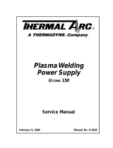
2T.05 Introduction to Plasma
A. Plasma Gas Flow
Plasma is a gas which has been heated to an ex-
tremely high temperature and ionized so that it
becomes electrically conductive. The plasma arc
cutting and gouging processes use this plasma to
transfer an electrical arc to the workpiece. The metal
to be cut or removed is melted by the heat of the arc
and then blown away.
While the goal of plasma arc cutting is separation of
the material, plasma arc gouging is used to remove
metals to a controlled depth and width.
In a Plasma Cutting Torch a cool gas enters Zone B,
where a pilot arc between the electrode and the torch
tip heats and ionizes the gas. The main cutting arc
then transfers to the workpiece through the column
of plasma gas in Zone C.
A-00002
Workpiece
Power
Supply
+
_
C
B
A
Typical Torch Head Detail
By forcing the plasma gas and electric arc through a
small orifice, the torch delivers a high concentration
of heat to a small area. The stiff, constricted plasma
arc is shown in Zone C. Direct current (DC) straight
polarity is used for plasma cutting, as shown in the
illustration.
Zone A channels a secondary gas that cools the torch.
This gas also assists the high velocity plasma gas in
blowing the molten metal out of the cut allowing for
a fast, slag - free cut.
B. Gas Distribution
The single gas used is internally split into plasma
and secondary gases.
Theplasmagasowsintothetorchthroughthe
negative lead, through the starter cartridge, around
the electrode, and out through the tip orifice.
Thesecondarygasowsdownaroundtheoutside
of the torch starter cartridge, and out between the
tip and shield cup around the plasma arc.
C. Pilot Arc
When the torch is started a pilot arc is established
between the electrode and cutting tip. This pilot arc
creates a path for the main arc to transfer to the work.
D. Main Cutting Arc
DC power is also used for the main cutting arc. The
negative output is connected to the torch electrode
through the torch lead. The positive output is con-
nected to the workpiece via the work cable and to
the torch through a pilot wire.
E. Parts - In - Place (PIP)
The torch includes a 'Parts - In - Place' (PIP) circuit.
When the shield cup is properly installed, it closes
a switch. The torch will not operate if this switch
is open.
A-02997
Torch Trigger
PIP Switch
Shield Cup
To Control
Cable Wiring
Torch Switch
Parts - In - Place Circuit Diagram for Hand Torch
PIP Sw itch
Sh ield Cup
To ATC
CNC Start
PIP Sw itch
Sh ield Cup
PIP Sw itch
Sh ield Cup
Remote Pendant
Automation To rch
To ATC
To ATC
Art # A-08168
Parts - In - Place Circuit Diagram for Machine Torch

CUTMASTER 152
INTRODUCTION Manual 0-4987
2T-4
This Page Intentionally Blank

CUTMASTER 152
Manual 0-4987 INSTALLATION
3-1
SECTION 3 SYSTEM:
INSTALLATION
3.01 Unpacking
1. Use the packing lists to identify and account for
each item.
2. Inspect each item for possible shipping damage.
If damage is evident, contact your distributor and
/ or shipping company before proceeding with
the installation.
3. Record Power Supply and Torch model and serial
numbers, purchase date and vendor name, in the
information block at the front of this manual.
3.02 Lifting Options
The Power Supply includes a handle for hand lifting
only. Be sure unit is lifted and transported safely and
securely.
!
WARNING
Do not touch live electrical parts.
Disconnect input power cord before moving
unit.
FALLING EQUIPMENT can cause serious
personal injury and can damage equipment.
HANDLE is not for mechanical lifting.
• Onlypersonsofadequatephysicalstrengthshould
lift the unit.
• Liftunitbythehandles,usingtwohands.Donot
use straps for lifting.
• Useoptionalcartorsimilardeviceofadequate
capacity to move unit.
• Placeunitonaproperskidandsecureinplace
before transporting with a fork lift or other vehicle.
3.03 Opening the Contactor Cover
The input power cord is connected to the main contactor,
the contactor is located inside a box with a snap on cover.
The cover is held in place with two or more snap lock
tabs. To remove the cover release the front latch and tilt
the cover up about ½ inch. Then squeeze both sides of
the cover and lift it straight up. See the Primary Input
Power Connections section for the necessary changes to
the Contactor. Remember to replace the Contactor Cover
when the changes are complete.
Art# A-11478
1
2
2
1
Contactor cover
3.04 Primary Input Power Connections
CAUTION
Check your power source for correct voltage
before plugging in or connecting the unit.
Check the Voltage Selector at the rear of the
unit for correct setting before plugging in
or connecting the unit. The primary power
source, fuse, and any extension cords used
must conform to local electrical code and the
recommended circuit protection and wiring
requirements as specified in Section 2.
The following illustration and directions are for changing
phase of the power supply.
Art # A-08493
Input Power Cable Connections
Three-Phase (3ø)
Store copper jumpers on base plate
Single-Phase (1ø) and Jumper Settings
GND
L1
L2
L3
L4
GND
L1
L2
L3
L4
Single and Three Phase Input Power Wiring
NOTE
There are two jumpers used for the single
phase 230V setting and none for three phase.
A. Connections to Single Phase Input Power
WARNING
Disconnect input power from the power
supply and input cable before attempting
this procedure.

CUTMASTER 152
INSTALLATION Manual 0-4987
3-2
CUTMASTER 152
Manual 0-4987 INSTALLATION
3-3
B. Connections to Three Phase Input Power
WARNING
Disconnect input power from the power
supply and input cable before attempting
this procedure.
These instructions are for changing the input power and
or cable on the 208/230, 400, 460 VAC Power Supply to
Three - Phase input power.
1. Remove the Power Supply cover per instructions
found in section 5.
2. Disconnect the original input power cable from
the main input contactor and the chassis ground
connection.
3. Loosen the through - hole protector on the back
panel of the power supply. Pull the original
power cable out of the power supply.
4. Using a customer supplied four - conductor input
power cable for the voltage desired, strip back
the insulation on the individual wires.
5. Pass the cable being used through the access
opening in the back panel of the power supply.
Refer to Section 2 for power cable specifications.
CAUTION
The primary power source and power cable
must conform to local electrical code and the
recommended circuit protection and wiring
requirements (refer to table in Section 2).
6. Connect the wires as follows.
• WirestoL1,L2andL3input.It doesnot
matter what order these wires are attached.
See previous illustration and on label in the
power supply.
• Green/YellowwiretoGround.
7. With a little slack in the wires, tighten the through
- hole protector to secure the power cable.
8. Reinstall the Power Supply cover per instructions
found in section 5.
9. Connect the opposite end of individual wires to
a customer supplied plug or main disconnect.
10. Connect the input power cable (or close the main
disconnect switch) to supply power.
3.05 Gas Connections
Connecting Gas Supply to Unit
The connection is the same for compressed air or high
pressure cylinders. Refer to the following two subsec-
tions if an optional air line filter is to be installed.
1. Connect the air line to the inlet port. The illustra-
tion shows typical fittings as an example.
NOTE
For a secure seal, apply thread sealant to the
fitting threads, according to manufacturer's
instructions.DonotuseTeontapeasa
thread sealer, as small particles of the tape
may break off and block the small air pas-
sages in the torch.
Art # A-07943
Hose Clamp
Regulator/Filter
Assembly
Inlet Port
Gas Supply
Hose
1/4 NPT or ISO-R
to 1/4” (6mm) Fitting
Air Connection to Inlet Port
Installing Optional Single - Stage Air Filter
An optional filter kit is recommended for improved fil-
tering with compressed air, to keep moisture and debris
out of the torch.
1. Attach the Single - Stage Filter Hose to the Inlet
Port.
2. Attach the Filter Assembly to the filter hose.
3. Connect the air line to the Filter. The illustration
shows typical fittings as an example.
NOTE
For a secure seal, apply thread sealant to the
fitting threads, according to the maker's in-
structions.DoNotuseTeontapeasathread
sealer, as small particles of the tape may break
off and block the small air passages in the
torch. Connect as follows:
These instructions are for changing the input power and
or cable on the 208/230, 400, 460 VAC Power Supply to
Single - Phase input power.
1. Remove the Power Supply cover per instructions
found in section 5.
2. Disconnect the original input power cable from
the main input contactor and the chassis ground
connection.
3. Loosen the through - hole protector on the back
panel of the power supply. Pull the original
power cable out of the power supply.
4. If the power cable being used is not the factory
- supplied cable, use a three - conductor input
power cable for the voltage desired and strip
back the insulation on the individual wires.
5. Pass the cable being used through the access
opening in the back panel of the power supply.
Refer to Section 2 for power cable specifications.
CAUTION
The primary power source and power cable
must conform to local electrical code and the
recommended circuit protection and wiring
requirements (refer to table in Section 2).
6. Connect the wires as follows.
• ConnectBusBarJumpersonthecontactoras
shown in prior illustration and on label in the
power supply.
• Green/YellowwiretoGround.
8. Reinstall the Power Supply cover per instructions
found in section 5.
9. Connect the opposite end of individual wires to
a customer supplied plug or main disconnect.
10. Connect the input power cable (or close the main
disconnect switch) to supply power.
Art # A-07944
Hose Clamp
1/4 NPT to 1/4"
(6mm) Fitting
Regulator/Filter
Assembly
Inlet Port
Gas Supply
Hose
Optional Single - Stage Filter Installation
Installing Optional Two - Stage Air Filter Kit
This optional two - stage air line filter is also for use on
compressed air shop systems. Filter removes moisture
and contaminants to at least 5 microns.
Connect the air supply as follows:
1. Attach the Two Stage Filter bracket to the back
of the power supply per instructions supplied
with the filter assembly.
NOTE
For a secure seal, apply thread sealant to the
fitting threads according to manufacturer's
instructions.DoNotuseTeontapeasa
thread sealer as small particles of the tape
may break off and block the small air pas-
sages in the torch.
2. Connect the two stage filter outlet hose to the
inlet port of the Regulator / Filter Assembly.
3. Use customer - supplied fittings to connect the air
line to the Filter. A 1/4 NPT to 1/4" hose barbed
fitting is shown as an example.

CUTMASTER 152
INSTALLATION Manual 0-4987
3-4
Regulator
Input
Gas Supply
Hose
1/4 NPT to 1/4”
(6mm) Fitting
Regulator/Filter
Assembly
2-Stage Filter
Inlet Port (IN)
Outlet Port
(OUT)
Two Stage
Filter
Assembly
Art # A-07945_AC
Hose Clamp
Optional Two - Stage Filter Installation
Using High Pressure Air Cylinders
When using high pressure air cylinders as the air supply:
1. Refer to the manufacturer’s specifications for
installation and maintenance procedures for high
pressure regulators.
2. Examine the cylinder valves to be sure they are
clean and free of oil, grease or any foreign mate-
rial.Brieyopeneachcylindervalvetoblowout
any dust which may be present.
3. The cylinder must be equipped with an adjust-
able high - pressure regulator capable of outlet
pressures up to 100 psi (6.9 bar) maximum and
owsofatleast300scfh(141.5lpm).
4. Connect supply hose to the cylinder.
NOTE
Pressure should be set at 100 psi (6.9 bar) at
the high pressure cylinder regulator.
Supply hose must be at least 1/4 inch (6
mm) I.D.
For a secure seal, apply thread sealant to the
fitting threads, according to manufacturer's
instructions.DoNotuseTeontapeasa
thread sealer, as small particles of the tape
may break off and block the small air pas-
sages in the torch.

CUTMASTER 152
Manual 0-4987 INSTALLATION
3T-1
SECTION 3 TORCH:
INSTALLATION
3T.01 Torch Connections
If necessary, connect the torch to the Power Supply.
Connect only the Thermal Dynamics model SL100 /
Manual or SL100 / Mechanical Torch to this power sup-
ply. Maximum torch leads length is 100 feet / 30.5 m,
including extensions.
WARNING
Disconnect primary power at the source be-
fore connecting the torch.
1. Align the ATC male connector (on the torch lead)
with the female receptacle. Push the male con-
nector into the female receptacle. The connectors
should push together with a small amount of
pressure.
2. Secure the connection by turning the locking nut
clockwise until it clicks. DO NOT use the locking
nut to pull the connection together. Do not use
tools to secure the connection.
1
2
Art # A-07885
Connecting the Torch to the Power Supply
3. The system is ready for operation.
Check Air Quality
To test the quality of air:
1. Put the ON
/ OFF switch in the ON (up)
position.
2. Put the Function Control switch in the SET
position.
3. Place a welding filter lens in front of the torch
and turn ON the air. Do not start an arc!
Any oil or moisture in the air will be visible on the
lens.
3T.02 Setting Up Mechanical Torch
NOTE
An adapter is required to be installed in the
power supply if converting a hand torch
system to operate a machine torch.
WARNING
Disconnect primary power at the source be-
fore disassembling the torch or torch leads.
The mechanical torch includes a positioning tube with
rack and pinch block assembly.
1. Mount the torch assembly on the cutting table.
2. To obtain a clean vertical cut, use a square to
align the torch perpendicular to the surface of
the workpiece.
/