Page is loading ...

Operating and
Servicing Instructions
for
Convertible - Rated
3
⁄4-Ton - 1
1
/2-Ton Nylon Strap Hoists
and 1 - 2-Ton Nylon Strap Hoists
3
⁄4 - 1
1
⁄2 Ton Catalog Numbers
Rubber Glove Models: Hotstick Models:
C309-0451 C309-0452
T309-0682 T309-0663
T309-0839 T309-0685
1 - 2 Ton Catalog Numbers
Rubber Glove Models: Hot Stick Models:
T309-0811 T309-0683
T309-0840
© 2003 Hubbell / Chance., 210 N. Allen St., Centralia, MO 65240 U.S.A.
Printed in USA
P309-0558
Rev. P
®
This guide does not claim to cover all details or variations in equipment, nor to provide
for all possible conditions to be met with concerning installation, operation, or
maintenance of this equipment. If further information is desired or if particular
problems are encountered which are not sufficiently covered in this guide, contact
Hubbell / Chance.
Refer to any questions about the use, application, repair or testing of this hoist to:
Hubbell / Chance
210 N. Allen St.
Centralia, MO 65240
Phone: (573) 682-5521
NOTE: Because Hubbell has a policy of continuous product improvement, we reserve the right to change
design and specifications without notice.
These instructions do not claim to cover all details or variations in equipment, nor
to provide for all possible conditions to be met concerning installation, operation,
or maintenance of this equipment. If further information is desired or if particular
problems are encountered which are not sufficiently covered in this guide, contact
Hubbell / Chance
®
®
POWER SYSTEMS, INC.

Hoist Capacity
-2-
Two hoist ratings are available. One is convertible for either 3/4 ton (1500 lb./675
kg.) or 1 1/2 ton (3000 lb./1350 kg.) capacity. The other is convertible for either 1-
ton (2000 lb./900 kg.) or 2-ton (4000 lb./1800 kg.) capacity.
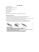
To rig the hoist for the higher rating, the strap must be run around the roller
(P309-0531) in the load hook yoke, and back to the lower clevis in the housing. The
housing loop pin (P309-0528) must be inserted through the loop in the end of the
strap attaching it to the housing. Secure the pin with a keeper ring (P309-0539)
inserted through the hole in both ends of the pin. (Refer to Fig. 1 and exploded
view).
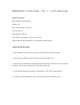
To rig the hoist for the lower rating, remove the housing loop pin (P309-0528),
remove the strap, and reinsert the pin in the housing for storage. Remove the pin
from the load hook yoke. Insert the yoke spool into the loop in the end of the strap.
Pin the yoke spool/strap loop end into the yoke using the loop pin. Secure the pin
with a keeper ring (P309-0539) inserted through the hole in both ends of the pin.
(Refer to Fig. 2 and exploded view).
NOTE: These hoists must be used with appropriate length insulating link sticks
if they are used in energized line work (see Chance
®
Catalog for insulated link
sticks that can be used with these hoists).
These hoists are not insulated live line tools.
Figure 1
Rigged for higher rating: Rubber
Glove style with regular hooks
and handle.
-3-
Figure 2
Handwheel
Shift Key
Lever
(Up/Down)
Release
Lever
Handle
Housing
Pin

-4-
REFER TO A.S.M.E. STANDARD 30.21 FOR MORE INFORMATION ON
OPERATION, MAINTENANCE, AND TESTING OF THIS HOIST.
FOR SAFE HOIST OPERATION:
1. NEVER operate this hoist if you are not familiar with how the hoist works.
2. NEVER lift people or loads over people.
3. NEVER use a hoist as a load binder.
4. NEVER use a hoist beyond rated capacity.
5. NEVER use replacement parts other than those supplied by A. B. Chance.
6. NEVER use a cheater or longer handle in the hoist.
7. NEVER allow the strap to come in contact with any object.
8. NEVER use the hoist if the pull is not hook to hook straight line.
9. NEVER leave a load suspended in the air.
10. NEVER use a hoist as a tow line.
11. NEVER use a hoist that is worn or malfunctioning.
Operating Instructions
CONSIDER THE WORK AREA
Determine the position and how the hoist is to be attached, based on the job to be
accomplished, the structure to which the hoist is to be attached, and the type and
weight of the load to be moved.
The hoist must be positioned so the load hook and housing hook are in a
straight line pull. The strap and/or housing must not be forced out of line
which could cause binding or damage to equipment. The handle and
controls of the hoist must be free to operate and not contact objects which
could cause the controls to move or damage the hoist.
The load must seat in the hook so the load is in line with the shank of the
hook and centerline of the strap. DO NOT LOAD HOOKS ON THE POINT.
The safety latches must be closed to secure the hook and prevent
accidental loss of the load. NEVER ALLOW LOAD TO BEAR ON SAFETY
LATCHES.
The strap may be quickly extended to hook to a load by operating the “RELEASE
LEVER” with the “SHIFT KEY LEVER” in the “DN” (DOWN) position.
The strap is painted red near the spool end.
NEVER LOAD THE HOIST WHEN THE RED PAINT ON THE STRAP CAN BE
SEEN.
CAUTION
LOWERING A LOAD (Requires more than 25 lb.)
Hold onto the handle, set the “SHIFT KEY LEVER” to the “DN” (DOWN) position.
Operate the handle until the “WORKING DOG” engages the ratchet wheel tooth.
Additional pressure on the handle in the same direction will release the “HOLDING
DOG”. Slowly move the handle, maintaining control, in the opposite direction,
lowering the load, until the “HOLDING DOG” engages the ratchet wheel. The
“WORKING DOG” will then release allowing the operator to repeat this movement
to lower the load.
When the load is completely off of the hoist, the strap “RELEASE LEVER” may
be operated to quickly extend the strap for unhooking.
NEVER LET THE HOIST SELF-RATCHET OR THE HANDLE TO FLY LOOSE. THE
QUICKLY MOVING HANDLE CAN CAUSE INJURY AND SELF-RATCHETING MAY
DAMAGE THE HOIST.
NEVER ATTEMPT TO OPERATE THE “RELEASE LEVER” WHILE THE HOIST IS LOADED.
-5-
NEVER OVERLOAD THE HOIST. NEVER USE A CHEATER OR EXTEND THE HANDLE.
Refer to Fig. 2 for identification of hoist controls.
The handwheel or eyenut, located on the side of the hoist, may be used to quickly
take up the slack strap prior to lifting the load. Move the “SHIFT KEY LEVER”
to the “UP” position and rotate the wheel or eyenut.
Lift the load by moving the handle in full, even strokes. Do not slam or jerk the
handle. If excessive force (more than 100 lb. for
3
/
4
-1
1
/
2
Ton —150 lb. for 1 - 2 Ton)
is required to operate the handle, the hoist is probably overloaded. Check the load
and/or rigging before proceeding. If the load is greater than the rating of the hoist
DO NOT LIFT THE LOAD.
ALWAYS INSPECT THE HOIST FOR WEAR, DAMAGE, AND PROPER OPERATION
BEFORE EACH USE.
Lifting Loads
MAKE SURE THE WORK AREA IS CLEAR OF ALL UNNECESSARY EQUIPMENT AND
PERSONNEL BEFORE MOVING A LOAD. PERSONNEL AND EQUIPMENT SHOULD
BE MOVED CLEAR OF THE AREA IN CASE THE LOAD SHOULD FALL.
If accessories, such as slings, wire grips or link sticks are used with the hoist, the
rated working load of these items must be equal to or greater than the load.
ONCE THE LOAD IS LIFTED INTO POSITION, THE “SHIFT KEY LEVER” MUST BE IN THE
“UP” POSITION FOR HOLDING THE LOAD. THIS WILL HELP PREVENT ACCIDENTAL
LOWERING OF THE LOAD.

-7--6-
Servicing Your Strap Hoist
REPAIR PARTS LIST
FOR CHANCE CONVERTIBLE RATED NYLON
STRAP NOISTS
PART NO.
E309-0849
E309-0850
P309-0512
P309-0513
P309-0473
P309-0531
P309-0528
P309-0523
P309-0522
P308-0540
P309-0541
P309-0526
P309-0547
P309-0545
P309-0871
P309-0524
P309-0525
P309-0537
P309-0532
P309-0527
P001-0017
P309-0808
P309-0539
P309-0519
P309-0515
P309-0517
P309-0872
P309-0533
P309-0546
E309-0853
E309-0854
P309-0426
P312-0027
E309-0843
P309-0392
P309-0475
P309-0474
E309-0851
E309-0852
P309-0690
P309-0829
P309-0272
P309-0848
P309-0835
DESCRIPTION
Housing Assembly (H/S)
Housing Assembly (R/G)
Handle Casting
Ratchet Spool
Strap
Yoke Spool
Loop Pin
Hand Wheel
Main Shaft
Bearing
Bearing
Idler Roller
Groove Pin
Roll Pin 3/16" x 1"
Release Lever
Holding Dog Shaft
Holding Dog
Dog Spring Pin
Snap Ring
Roll Pin 1/8" x 7/8"
Body Spring Pin
Pawl Control Assembly
Split Ring
Working Dog Shaft
Working Dog
Reversing Rod
Reversing Cam
Bearing
Roll Pin 5/32" x 1 1/2"
Load Hook Assy. (1-2T R/G) Bronze Yoke
Load Hook Assy. (1-2T H/S) Bronze Yoke
Label
Label
Handle 40" Lg. w/Guard
Latch Assembly (R/G)
Handle 30" Lg. (H/S)
Handle 30": Lg. (R/G)
Load Hook Assy. (R/G) Aluminum Yoke
Load Hook Assy. (H/S) Aluminum Yoke
Handle 36" Lg. (R/G)
Ball-Lok Pin
Roll Pin
Eye Nut (H/S)
Long Shaft
ITEM
1
2
3
4
5
6
7
8
9
10
11
12
13
14
15
16
17
18
19
20
21
22
23
24
25
26
27
28
29
30
31
32
33
34
35
36
37
38
39
40
41
42
43
44

-8-
DISASSEMBLY PROCEDURE
1. Unroll the strap from the hoist by following the procedures outlined
previously for extending the strap. When the strap is fully extended, the
spool (P309-0512) will be exposed. Locate the roll pin (P309-0546) which
goes through the spool. Using a long 1/8" punch, drive this roll pin completely
out of the spool.
2. Remove the retaining ring (P309-0532) from the handle end of the main
shaft (P309-0522). Holding the handle and spool, grasp the handwheel and
pull the main shaft from the hoist. CAUTION WHEN THE SHAFT IS
REMOVED, THE HANDLE ASSEMBLY, SPOOL, AND STRAP WILL BE
LOOSE AND COULD FALL.
3. Lay the handle assembly aside. The spool and strap can be removed from the
housing. If the strap is to be removed completely, it may be necessary to drive
pin (P309-0547) from the lower housing. Use a 1/4" punch and drive the pin
from the handle side of the hoist toward the handwheel side. Remove the pin
and idler roller (P309-0526).
HOUSING SUB-ASSEMBLY
1. Remove the roll pin (P309-0527) from the holding dog (P309-0525).
2. Disconnect pawl control spring (P309-0808) from the housing. Leave the
spring attached to holding dog unless the spring or dog must be replaced.
3. Remove the retaining ring (P309-0532) from the handle end of the holding
dog shaft (P309-0524). Remove the shaft from the housing.
HANDLE SUB-ASSEMBLY
1. Remove the roll pin (P309-0527) from the reversing cam (P309-0869).
2. Locate the retaining ring (P309-0532) on the lever end of the working dog
shaft (P309-0519). Slide this ring down the shaft toward the working dog
(P309-0515) approximately 2 inches.
3. Slide the working dog and shaft out of the handle housing (P309-0512).
Remove the reversing cam (P309-0869), working dog (P309-0515), and
reversing rod (P309-0517).
4. If it is necessary to fully remove the working dog and shaft (P309-0519) for
repairs, remove the two retaining rings (P309-0532) from the shaft.
ALWAYS WEAR SAFETY GLASSES AND OTHER APPROPRIATE PROTECTIVE
EQUIPMENT DURING THE FOLLOWING PROCEDURES. USE THE CORRECT TOOLS
FOR THE OPERATIONS BEING PERFORMED.
-9-
Care and Service of Your Hoist
Your Chance hoist will give many years of satisfactory performance if used and
maintained properly.
Always hang the hoist freely with a straight line between the housing hook and
the load hook. DO NOT JAM THE HOIST OR STRAP AGAINST ANY OBJECT.
THIS HOIST IS INTENDED FOR INDUSTRIAL OR UTILITY USE AND IS
NEVER TO BE USED FOR LIFTING PEOPLE OR LOADS OVER PEOPLE.
The Chance hoist is extremely easy to care for. The open frame construction makes
it a simple task to clean and inspect. You will add years of life to the hoist by
applying the following recommendations.
1. Do not use the hoist if it does not operate properly or is damaged in any way.
2. Do not allow the strap to be pulled over any sharp edge or wrapped around
a pole or crossarm. Always use a sling or other means of attachment.
3. Stop pulling before the load hook is pulled tight to the housing. Continued
pulling into the housing may damage the hoist.
4. Never allow the handle to fly free, or the hoist to self-ratchet.
5. Never throw or drop the hoist. Doing so can damage the hoist.
6. Keep the strap clean. Inspect the strap and hoist before each and every use.
Do not use a hoist if the strap is frayed, cut or damaged.
7. All hoists must be periodically cleaned, inspected and re-lubricated. Intervals
will depend on usage. The bronze bearings and all moving parts of the hoist
must be re-lubricated with 30 wt. oil or a light grease.
8. Extra care must be used when lowering a light or “bouncing” load such as a
span of conductor. If the handle is “flipped” the hoist can self-ratchet which
causes severe wear on the dogs, ratchet teeth, and stop areas of the hoist.
9. When operating the handle, do not “slam” the handle. A smooth, steady
pressure in each direction moves the load efficiently and does not cause
damage to the equipment.

-10-
Inspection
Thoroughly clean all metal parts with solvent and dry. The Epoxiglas handle can
be cleaned and refinished as any Chance hot line tool. Refer to Chance catalog for
cleaning and refinishing supplies.
DO NOT ATTEMPT TO CLEAN THE STRAP. IF THE STRAP IS DIRTY OR
CONTAMINATED, IT MUST BE REPLACED.
Inspect the strap for any signs of wear, torn threads or stitching, frayed edges or
cuts. Discoloration is a sign that the strap should be replaced. If there is any doubt
about the integrity of the strap, replace it.
Inspect all metal parts for wear. This includes rounded edges, elongated holes,
battered areas caused by impacts. All castings should be inspected closely for
cracks or other signs of damage.
Inspect the ratchet spool closely for damage to the teeth. Special attention should
be given to the “working surfaces” of the teeth. If the top of a tooth is rounded or
sheared off from impact, the spool must be replaced. Look carefully at the spool
area where the strap winds for sign of crushing caused by severe overloading.
Inspect the hooks for signs of bending or opening of the hook throat.
Safety latches must be in place and working properly.
All springs, including the reversing rod, should be inspected for signs of wear or
bending. The reversing rod should be straight on the long leg.
Any bending of the
long leg indicates need for replacement.
Inspect the bronze bearings in the housing for wear or elongation. Replace any
questionable bushings or if desired, the entire housing assembly.
Assembly
After all worn or damaged parts have been identified and replaced, the hoist may
be reassembled in reverse order of disassembly. All bronze bearings must be
lubricated with 30 wt. oil. All sliding or moving parts on shafts, etc. must be
lubricated with a thin coating of light grease.
The hoist should not require great force to assemble with the exception of driving
of roll pins. If parts will not fit together easily, it is likely that something is bent
or damaged. Identify the problem before proceeding.
-11-
After assembly, the hoist must be checked for proper operations and load tested.
Suspend the hoist from a support that can hold the test loads. With a load of 100
lb. on the hoist, carefully raise and lower the load. The handle should be operated
to rotate the ratchet spool at least one complete revolution (16 teeth) in one tooth
increments to insure all teeth are tested.
A load equal to the rating of the hoist should then be raised and lowered in a similar
manner. Attention to the operation of all controls, and the action of the dogs during
testing, is essential to make sure the hoist is safe to return to duty. If the hoist
passes the above tests, the hoist may be returned to the user.
It is recommended that the user establishes a procedure for the routine inspection,
repair and testing of this hoist, based on usage, to ensure a safe working
environment.
Testing
/