TRINAMIC / ANALOG DEVICES TMC2590-EVAL-KIT Operating instructions
- Type
- Operating instructions

Evaluation Board for Stepper Motors EVALUATION BOARD
TMC2590-EVAL Evaluation Board
Document Revision V1.0 •2019-AUGUST-16
The TMC2590-EVAL is designed for evaluating all features of the TMC2590-TA. The evaluation board
is part of TRINAMICs user-friendly plug-in system for chip evaluation. Just connect the TMC2590-
EVAL with Landungsbruecke, the associated base board to start driving a motor in position or
velocity mode.
Features
•
Servo Controller for DC, BLDC and
stepper motors
•
Control of torque (FOC), velocity and
position by cascade control
•Integrated Delta Sigma ADCs
•
5V Supply Voltage (onboard buck
converter for VCCIO 3.3V)
•
SPIand UART for communication
with Microcontroller
•Realtime Monitoring Interface
•
ABN Encoder Interface, Digital Hall
Interface, Analog Hall Interface, Sine/-
Cosine Encoder and Ref.-Switch In-
put
Applications
•Laboratory Automation
•Manufacturing
•Semiconductor Handling
•Robotics
•Factory Automation
•Test & Measurement
•Life Science
•Biotechnology
•Liquid Handling
Simplified Block Diagram
©2019 TRINAMIC Motion Control GmbH & Co. KG, Hamburg, Germany
Terms of delivery and rights to technical change reserved.
Download newest version at: www.trinamic.com
Read entire documentation.

TMC2590-EVAL Evaluation Board •Document Revision V1.0 •2019-AUGUST-16 2 / 11
Contents
1 Getting Started 3
1.1 First Start-Up ................................................. 4
2 Hardware Information 5
3 Evaluation Features in the TMCL-IDE 6
3.1 Velocity Mode ................................................ 6
3.2 Position Mode ................................................ 7
3.3 StallGuard2™Tuning ............................................ 8
3.4 CoolStep™Tuning .............................................. 9
4 Revision History 11
4.1 Document Revision ............................................. 11
©2019 TRINAMIC Motion Control GmbH & Co. KG, Hamburg, Germany
Terms of delivery and rights to technical change reserved.
Download newest version at www.trinamic.com

TMC2590-EVAL Evaluation Board •Document Revision V1.0 •2019-AUGUST-16 3 / 11
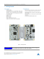
1 Getting Started
You need
•TMC2590-EVAL
•
Landungsbruecke or Startrampe with latest
firmware (We recommend the Landungs-
bruecke as it offers faster USB communication.)
•1 x Eselsbruecke
•Stepper motor
•USB interface
•Power Supply
•Latest TMCL-IDE V3.0 and PC
•Cables for interface, motors and power
Precautions
•
Do not mix up connections or short-circuit pins.
•Avoid bounding I/O wires with motor wires.
•
Do not exceed the maximum rated supply sup-
ply voltage!
•
Do not connect or disconnect the motor while
powered!
•START WITH POWER SUPPLY OFF!
Figure 1: Getting started
NOTICE
The Landungsbruecke operates on USB Power Supply. All other voltages are
generated from V_M. Kit works only, when V_M is applied.
©2019 TRINAMIC Motion Control GmbH & Co. KG, Hamburg, Germany
Terms of delivery and rights to technical change reserved.
Download newest version at www.trinamic.com

TMC2590-EVAL Evaluation Board •Document Revision V1.0 •2019-AUGUST-16 4 / 11
1.1 First Start-Up
1.
Make sure that the latest version of the TMCL-IDE is installed. The TMCL-IDE can be downloaded
from www.trinamic.com/support/software/tmcl-ide/.
2. Open the TMCL-IDE and connect the Landungsbruecke or Startrampe via USB to the computer. For
Windows 8 and higher is no driver needed, on Windows 7 machines the TMCL-IDE is installing the
driver automatically.
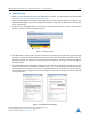
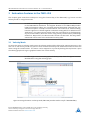
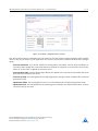
3.
Verify that the Landungsbruecke or Startrampe is using the latest firmware version. The firmware
version is shown in the connected device tree.
Figure 2: Firmware Version
4.
The TMCL-IDE 3.0 needs room to show all important information and to provide a good overview.
Therefore, arrange the main window related to your needs. We recommend using full screen. For
evaluation boards it is essential to have access to the registers. Therefore open up the Register
Browser (left side). For a better view click top right on the normal icon to get a maximized register
browser window.
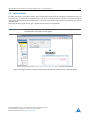
5.
The TMCL-IDE includes a dialogue for diagnostic tasks. Further, the dialogue provides an overview
of the connected motion controller and driver chips. Thus, a window pops up immediately after
connecting the evaluation kit the first time. The window shows the actual status of the connections.
The second tab of the dialogue offers the possibility to choose basic settings or to reset the module
to factory defaults.
Figure 3: Landungsbruecke Dialogue
©2019 TRINAMIC Motion Control GmbH & Co. KG, Hamburg, Germany
Terms of delivery and rights to technical change reserved.
Download newest version at www.trinamic.com

TMC2590-EVAL Evaluation Board •Document Revision V1.0 •2019-AUGUST-16 5 / 11
2 Hardware Information
All design files for our evaluation boards are available for free. We offer the original ECAD files (Eagle,
Altium, or PADS), Gerber data, the BOM, and PDF copies.
The files can be downloaded from the evaluation boards’website directly at
.
Note
Iffiles are missing on the website or something is wrong please send us a note.
©2019 TRINAMIC Motion Control GmbH & Co. KG, Hamburg, Germany
Terms of delivery and rights to technical change reserved.
Download newest version at www.trinamic.com

TMC2590-EVAL Evaluation Board •Document Revision V1.0 •2019-AUGUST-16 6 / 11
3 Evaluation Features in the TMCL-IDE
This chapter gives some hints and tips on using the functionality of the TMCL-IDE, e.g. how to use the
velocity mode or using the wizards.
Note
In order to achieve good settings please refer to descriptions and flowcharts
in the TMC2590-TA datasheet. The register browser of the TMCL-IDE provides
helpful information about any currently selected parameter. Beyond that, the
datasheet explains concepts and ideas which are essential for understanding
how the registers are linked together and which setting will fit for which kind of
application. For getting more familiar with the evaluation kit in the beginning
of your examinations, drive the motor using velocity mode and/or positioning
mode first. Beyond this, the direct mode function can be used. This way, TMCL
commands can be sent to the evaluation board system.
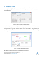
3.1 Velocity Mode
To move the motor in velocity mode, open the velocity mode tool by clicking the appropriate entry in the
tool tree. In the velocity mode tool you can enter the desired velocity and acceleration and then move the
motor using the arrow buttons. The motor can be stopped at any time by clicking the stop button. Open
the velocity graph tool to get a graphical view of the actual velocity.
Note
In order to get a more accurate graphical velocity view, close the register browser
window when using the velocity graph.
Figure 4: Driving the motor in velocity mode (TMCL-IDE provides similar view for TMC2590-EVAL)
©2019 TRINAMIC Motion Control GmbH & Co. KG, Hamburg, Germany
Terms of delivery and rights to technical change reserved.
Download newest version at www.trinamic.com

TMC2590-EVAL Evaluation Board •Document Revision V1.0 •2019-AUGUST-16 7 / 11
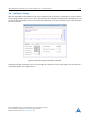
3.2 Position Mode
To move the motor in position mode, open the position mode tool by clicking the appropriate entry in
the tool tree. In the position mode tool you can enter a target position and then start positioning by
clicking the Absolute or Relative Move button. The speed and acceleration used for positioning can also be
adjusted here.
Open the position graph tool to get a graphical view of the actual position.
Note
In order to get a more accurate graphical position view, close the register browser
window when using the position graph.
Figure 5: Driving the motor in position mode (TMCL-IDE provides similar view for TMC2590-EVAL)
©2019 TRINAMIC Motion Control GmbH & Co. KG, Hamburg, Germany
Terms of delivery and rights to technical change reserved.
Download newest version at www.trinamic.com

TMC2590-EVAL Evaluation Board •Document Revision V1.0 •2019-AUGUST-16 8 / 11
3.3 StallGuard2™Tuning
To tune StallGuard2
™
properly you need to set the current for the motor first, e.g. 1A RMS. After that
you specify the velocity to run the motor with. This could be 75 rpm as in this example. You can use the
TMCL IDE to calculate the velocity with the "Parameter calculator" tool shown in the list on the left when
connecting the board.
Figure 6: TMCL IDE v3.0.20.0 Parameter calculator
In the TMCL IDE you can use the CoolStep
™
& StallGuard2
™
graph where the StallGuard2
™
value is shown
in blue. There are two parameters that need tuning for proper StallGuard2
™
use. StallGuard2
™
Threshold
(SGT), will need to be tuned by raising or lowering the SGT value. The goal of SGT it so have it hit 0 before a
stall occurs. If the SGT is too high, a step loss will occur and you need to lower it. In the picture you see
two regions. In the first region the SGT value was too high. It was set to 10 and with loading the motor you
can see the value does not reach 0. In the second region the SGT value was set to 4 which results in hitting
the 0 axis just short before the motor stalls.
Figure 7: CoolStep™& StallGuard2™window
With optimal StallGuard2™settings you can optionally activate CoolStep™.
©2019 TRINAMIC Motion Control GmbH & Co. KG, Hamburg, Germany
Terms of delivery and rights to technical change reserved.
Download newest version at www.trinamic.com

TMC2590-EVAL Evaluation Board •Document Revision V1.0 •2019-AUGUST-16 9 / 11
3.4 CoolStep™Tuning
With the TMCL IDE and the EVAL-KIT you have a powerful tool to find your CoolStep
™
to run your motor
most energy efficient and cool. To tune it, please open the CoolStep
™
& StallGuard2
™
window you’ll find
on the left of the IDE when you have connected the EVAL board. On the CoolStep
™
tab you will see below
picture by default.
Figure 8: TMCL IDE v3.0.20.0 Parameter calculator
CoolStep
™
will get activated as soon as you change the "Hysteresis start" value higher than 0 and enter a
"Threshold speed" value higher than 0.
©2019 TRINAMIC Motion Control GmbH & Co. KG, Hamburg, Germany
Terms of delivery and rights to technical change reserved.
Download newest version at www.trinamic.com

TMC2590-EVAL Evaluation Board •Document Revision V1.0 •2019-AUGUST-16 10 / 11
Figure 9: CoolStep™& StallGuard2™window
The above values activate CoolStep
™
but the values can be fine tuned to make CoolStep
™
work reliable
and in a way as you need it in your application. For that it is important to understand what each setting is
doing.
•Current minimum
: The current minimum setting will be the lowest current when CoolStep
™
is
activated. With 1A RMS the current will either be reduced to a quarter or to the half of this current
when no or less force is applied to the motor shaft.
•Current down step
: Current down steps defines the speed of the current to drop down after load
gets released from the motor shaft.
•Current up step
: This setting defines the step height when hitting the lower StallGuard2
™
threshold
(Hysteresis start).
•Hysteresis width: This setting defines the area of the StallGuard2™threshold (Hysteresis end).
•Hysteresis start
: This setting defines the switching point, related to the StallGuard2
™
value, to boost
up the current by one step.
©2019 TRINAMIC Motion Control GmbH & Co. KG, Hamburg, Germany
Terms of delivery and rights to technical change reserved.
Download newest version at www.trinamic.com

TMC2590-EVAL Evaluation Board •Document Revision V1.0 •2019-AUGUST-16 11 / 11
4 Revision History
4.1 Document Revision
Version Date Author Description
1.0 2019-AUG-16 LH Initial creation.
Table 1: Document Revision
©2019 TRINAMIC Motion Control GmbH & Co. KG, Hamburg, Germany
Terms of delivery and rights to technical change reserved.
Download newest version at www.trinamic.com
-
 1
1
-
 2
2
-
 3
3
-
 4
4
-
 5
5
-
 6
6
-
 7
7
-
 8
8
-
 9
9
-
 10
10
-
 11
11


TRINAMIC / ANALOG DEVICES TMC2590-EVAL-KIT Operating instructions
- Type
- Operating instructions
Ask a question and I''ll find the answer in the document
Finding information in a document is now easier with AI
Related papers
-
TRINAMIC / ANALOG DEVICES TMC2209-EVAL User manual
-
-
-
-
-
-
-
-
-
Other documents
-
Trinamic TMC2226-EVAL User manual
-
-
-
-
-
-
-
-
-