Page is loading ...

© 2004 ITW Finishing Systems and Products 1
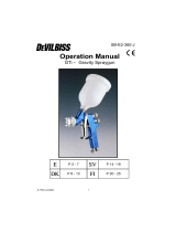
Binks “STEADI-GRIP”
2 QT. PRESSURE CUPS
Model No. 80-295-CE
SB-E-4-231
ISS.01
SPECIFICATIONS
MAX. WORKING PRESSURE . . . . . . . . . . . . . . . . . . . . 50 psig 3.5 bar
OVERALL HEIGHT
WITH AUXILIARY HANDLE . . . . . . . . . . . . . . . . . 16 15/16 in 430 mm
WITHOUT AUXILIARY HANDLE . . . . . . . . . . . . . 13in 330 mm
BASE DIAMETER . . . . . . . . . . . . . . . . . . . .. . . . . . . . . . 5 1/4in. 133 mm
AIR INLET & OUTLET CONNECTION SIZE . .. . . . . . . . 1/4 NPS (m) -
FLUID OUTLET CONNECTION SIZE . . . . . . .. . . . . . . . 3/8 NPS (m) -
FLUID CAPACITY. . . . . . . . . . . . . . . . . . . . . . . . . . . . . . 2 Qts (US) 1.9 Ltr
WEIGHT. . . . . . . . . . . . . . . . . . . . . . . . . . . . . . . . . . . . . . 3 lb.3oz. 1.46 kg

© 2004 ITW Finishing Systems and Products 2
The following hazards may occur during the normal use of this equipment. Please read the following
chart.
HAZARD CAUSE SAFEGUARDS
FIRE
Solvents and coatings can be
highly combustible, especially
when sprayed.
1. Adequate exhaust must be provided
to keep the air free of
accumulations of flammable
vapours
2. Smoking must never be allowed in
the spray area.
3. Fire extinguishing equipment must
be present in the spray area.
FIRE - PRESSURE CUP Vapours from flammable liquids
can catch fire or explode
1. Keep Cup at least 3 metres away
from sources of ignition, including
hot surfaces, mechanical sparks
and arcing (non-explosion proof)
electrical equipment.
2. Electrostatic charges may
accumulate and may ignite
flammable vapours by brush
discharges. Ensure the Cup is
earthed with conductive air or fluid
hoses or earthing clamp.
INHALING TOXIC
SUBSTANCES
Certain materials may be
harmful if inhaled, or there is
contact with the skin.
1. Follow the requirements of the
Material Safety Data Sheet supplier
by the coating manufacturer.
2. Adequate exhaust must be provided
to keep the air free of
accumulations of toxic materials.
3. Use a mask or respirator wherever
there is a risk of inhaling sprayed
materials. The mask must be
suitable for the material being
sprayed.
EXPLOSION, PRESSURE
TANK—RUPTURE
Making any changes or
modification to the pressure Cup
may weaken it.
1. Never drill into, weld or modify the
Cup in any way.
2. Do not adjust, remove or tamper
with the safety valve.
3. Only replace the safety valve with
the correct spare part as listed.
4. Do not fit any other safety valve of a
higher pressure rating than the
maximum working pressure of the
Cup.
GENERAL SAFETY Improper operation or
maintenance may create a
hazard.
Operators should be given adequate
training in the safe use and
maintenance of this equipment. Refer
to Pressure Systems Safety
Regulations 2000 Approved Code of
Practice or other national codes.
WARNING

© 2004 ITW Finishing Systems and Products 3
SETUP AND OPERATION
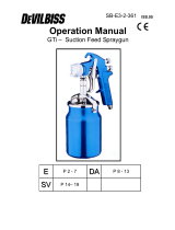
Refer to “TYPICAL INSTALLATION” drawing below
Set up the “Steadi-Grip” with the CONVENTIONAL or HVLP gun along with at least 1.5m (5 ft.) of air
and fluid hose. Attach air hose from extractor to air inlet on handle of steadigrip assembly. Pour paint
into canister with liner. Re-attach lid to canister and firmly tighten four knobs over canister lid. Set air
pressure from air regulator mounted on extractor and fluid pressure by adjusting fluid pressure
adjustment knob on cup handle.
INTRODUCTION
Binks “Steadi-Grip” Pressure Cups are CE marked in accordance with the
ATEX Directive 94/9/EC, Cat 2 G X for use in Zones 1 and 2.
These Cups are ideal for component spraying and industrial applications where small batch
production spraying is required. The 2 qt. capacity is sufficient to complete large spray jobs without
refilling the cup. Its lightweight and rugged construction is excellent for portability allowing the
operator to make fluid and air control adjustments quickly and efficiently at the spray station.
NOTE
Before refilling canister with paint, shut
odd air supply to the cup and release
pressure from canister by rotating pres-
sure relief knob counter clockwise
WARNING
Chlorinated solvents and aluminum are incompatible and
will cause an adverse chemical reaction, possibly resulting
in bodily injury. Under NO circumstances should
chlorinated solvents be used with the “Steady Grip
Pressure Cup”.
CAUTION
Do not exceed 100 PSIG input air pressure
into the cup. Excessive pressure could dam-
age components
WARNING
All air and fluid pressure in the system must be relieved
before servicing the cup and before cup is filled or cleaned.
Attempting to service the cup while pressurized could result
in damage to components or personal injury.

© 2004 ITW Finishing Systems and Products 4
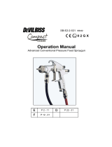
PARTS LIST
ITEM
NO
PART
NO
DESCRIPTION QTY
1 20-353-1 HEX JAM NUT 5/16" 1
4 † 72-1022 CENTER POST ASSEMBLY 1
5 80-4 CUP (2 Quart) 1
6 ○ 80-11-5 COVER GASKET (Tri Seal
Foam) 1
7 80-12 RELIEF VALVE STEM 1
8 80-267 CHECK VALVE 1
9 ○ 60-7 CHECK VALVE SPRING 1
10 80-33 FLUID OUTLET 1
11 80-34 FLUID TUBE (2 Quart) 1
14 * 80-45 COVER GASKET
(Leather)................ 1
15 80-297 CONTAINER COVER
1
17 83-1899 HANDLE
1
18 ▲ 85-440 REGULATOR ASSEMBLY 1
* Accessories available
▲ Item 18 ref. Part Sheet 2417
† Available from Industrial Finishing distributors only
○ Available only as 5-pack

© 2004 ITW Finishing Systems and Products 5
MODEL 80-295 PRESSURE CUP

© 2004 ITW Finishing Systems and Products 6
Refer to “TYPICAL INSTALLATION” drawing
below
Set up the “Steadi-Grip” with the CONVENTIONAL or
HVLP gun along with at least 5 ft. of air and fluid
hose. Attach air hose from extractor to air inlet on
handle of steadigrip assembly. Pour paint into
canister with liner.
Re-attach lid to canister and firmly tighten four knobs
over canister lid. Set air pressure from air regulator
mounted on extractor and fluid pressure by adjusting
fluid pressure adjustment knob on cup handle.
CLEANING
1. Open air release valve on pressure cup cover.
2. Reduce pressure in cup until gauge reads zero,
(turn knob counter-clockwise).
3. Loosen cup cover and set fluid tube on angle in
cup.
4. Loosen air nozzle two turns, place cloth over
nozzle and pull the trigger to force paint into cup.
5. Remove cover and clean cup and cover
thoroughly.
6. With approximately 1/4 to 1/2 cup of clean solvent,
attach cover and set fluid pressure at
approximately 10 PSI.
7. Close air adjusting valve at spray gun.
8. Trigger gun and allow solvent to flow into a
container until it flows clear.
9. Remove solvent, then clean air nozzle. If any dirt
appears in orifice, clean with tooth pick; wire will
damage nozzle. Blow nozzle and cup dry.
NOTE
Before refilling canister with paint, shut
off air supply to the cup and release
pressure from canister by rotating
pressure relief knob counter clockwise
WARNING
Chlorinated solvents and aluminum are
incompatible and will cause an adverse
chemical reaction, possibly resulting in bodily
injury. Under NO circumstances should
chlorinated solvents be used with the “Steady
Grip Pressure Cup”.
WARNING
All air and fluid pressure in the system must
be relieved before servicing the cup and before
cup is filled or cleaned. Attempting to service
the cup while pressurized could result in
damage to components or personal injury.
SETUP AND OPERATION

© 2004 ITW Finishing Systems and Products 7
EC DECLARATION OF CONFORMITY
We: ITW Finishing UK
Ringwood Rd
Bournemouth
Dorset
BH11 9LH
UK
As the manufacturers representative of the items listed below:
TYPE : SG Pressure Feed Cup
MODEL: 80-295-CE
Declare, under our sole responsibility, that the equipment to which this
document relates is in conformity with the following standards or
other normative documents:
EN 13463-1:2001
And thereby conform to the protection requirements of Council
Directive 94/9/EC relating to Equipment and Protective Systems
intended for use in Potentially Explosive Atmospheres protection;
level II 2 G X.
Approved by:
P C Loveless
Manufacturing Engineering Manager
Date: 1/12/2004

© 2004 ITW Finishing Systems and Products 8
ITW Finishing Systems and Products
Ringwood Road,
Bournemouth,
BH11 9LH,
England.
Tel. No. (01202) 571111
Telefax No. (01202) 581940,
Website address http://www.itweuropeanfinishing.com
ITW Oberflächentechnik GmbH & Co. KG
Justus-von-Liebig-Straße 31
63128 Dietzenbach
Tel (060 74) 403-1
Telefax: (060 74) 403300
Website address http://www.itw-finishing.de
ITW Surfaces Et Finitions
163-171 avenue des Auréats B.P. 1453
26014 VALENCE CEDEX FRANCE
Tél. (33) 475-75-27-00
Télex 345 719F DVILBIS
Téléfax: (33) 475-75-27-99
ITW Finishing Systems and Products is a Division of ITW Ltd. Reg. Office:
Admiral House,
St Leonard’s Road,
Windsor,
Berkshire,
SL4 3BL,
UK
Registered in England: No 559693 Vat No 619 5461 24
/