Page is loading ...

1257016-GB_v1.2
CONT-R15
1
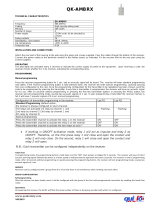
GENERAL DESCRIPTION
Control panel for 24 Vdc motors on sectional, swing, folding and sliding doors for residential and
communal use.
Basic features:
- self-programming
- stoppage by consumption
- receiver incorporated (15 codes) / pluggable receiver (433.92 (two-channel)/ 868.35
MHz)
- resistive safety edge inlet (8 k2)
- encoder inlet (sensor hall, ...)
- slow-speed start of operations (programmable)
- slow-speed end of operations (selectable)
- connection to portable programmer
TECHNICAL CHARACTERISTICS
Panel supply 0-12-24Vac
Transformer 0-12-24Vdc / 100VA or 150VA
Receiver 868.35MHz incorporated 15 codes
Optional cards Pluggable receiver card (433,92 (bi-channel) / 868,35 MHz) and
traffic light card (TL-CARD)
Security device output 24V ac / 1A
Operating temperature -20ºC to +85ºC
Airtightness IP54
Equipment category Class II
Base plate size 160x83x27 mm
Box dimensions 225x195x85 mm
BASE PLATE DESCRIPTION
1 2 3 4 5 6 7 8 9 10 11 12 13 14 15 16 17 18 19 20 21 22 23 24

1257016-GB_v1.2
CONT-R15
2
CONNECTION
1 Primary 230V ac Transformer + 230Vac power supply (L)
2 Primary 230V ac Transformer + 230Vac power supply (N)
3 Secondary 0V ac Transformer
4 Secondary 12V ac Transformer
5 Secondary 24V ac Transformer
6 24V ac output
7 24V ac output
8 24V dc motor output
9 24V dc motor output
10 Encoder (+)
11 Encoder (S.H.)
12 Encoder (-)
13 Common buttons
14 Stop (STOP) (NC)
15 Start (START) (NO)
16 Common buttons
17 Open (OPEN) (NO)
18 Close (CLOSE) (NO)
19 Common securities
20 Close security contact (NC) (SEC.CL)
21 Resistive security edge 8K2 (S.EDGE)
22 Common ends of run
23 End of run close (NC) (FC.CL)
24 End of run open (NC) (FC.OP)
INSTALLATION
Any handling of the panel for installation must be carried out with the power supply disconnected.
FITTING THE CASING (only box version)
· Parts: front casing and container box.
· Unscrew the securing points. Insert the cables through the lower holes.
IMPORTANT CONSIDERATIONS FOR START-UP
Where inversions are made, the panel adds time to ensure the door closes.
Any optional cards must be connected to the panel with the power supply disconnected.

1257016-GB_v1.2
CONT-R15
3
OPERATING
Start (START): Contact normally open to open and close. The first press opens, the second press
stops (until the limit switch) and the third closes. If it is pressed while the door is closing, it will
stop and invert the operation.
Stop (STOP): Contact normally closed. This detains the operation on standby for a new order.
Where not used, turn option 1 on the input switch to ON.
Open (OPEN): Contact normally open to open. If it is pressed while the door is closing, it will stop
and open.
Close (CLOSE): Contact normally open to close. If it is pressed while the door is closing, it
will stop
and close.
Security contact (SEC.CL): Contact normally closed, photocell or magnetic detector type. This
acts on closing, causing stoppage and inversion. Where not used, turn option 2 on the input
switch to ON.
Security edges (S.EDGE): Resistive contact for resistive security edge. This acts on closing, causing
stoppage and inversion. Where not used, turn option 3 on the input switch to ON.
Where option 6 of the options switch is turned to ON, the band is inhibited during the last 4 cm of
door closure.
Ends of run (FC.CL / FC. OP): contacts normally closed to mechanically indicate the open and
closed end of run. Where not used, turn option 4 or 5 on the input switch to ON.
24Vac outlet enables any unit to be powered at a voltage of 24Vac with a maximum consumption
of 1A.
Encoder inlet (+, S.H., -): Allows for an NPN-type encoder (or sensor hall) to be connected at 5Vdc,
necessary for the operation by pulses.
Reference search function: If the panel loses power halfway through the operation, on receiving
power it goes into reference search mode, in such a way that the door will move until a mechanical
stop or the end of the run is reached, with preference given to the opening reference, if it exists.
Reference search is indicated by the corresponding flashing of the SAFETY light (see table).
The Aut ref Search parameter (configurable by means of programmer) is selected if the user requires
this automatic search or wishes to wait for the START button to be pressed for the reference search.
N.B.: The panel may lose the reference if the power is disconnected halfway through the operation.
Door operation control function with external clock: By connecting an external clock or timer
(normally open) between the common push button terminal (16) and the bridged Open and Close
terminals (17 and 18), it is possible to temporize the opening and closing of the door.
Back Jump Function: With this function, the panel causes a small delay in the door at the end of
the operation to prevent voltage in the mechanism or to avoid pressure on the safety edge, where
applicable. The time of the delay can be defined using advanced programmer parameters.
OPTION SWITCH
Option No. Upper position – ON Lower position - OFF
1 (AUTO PROG) Self-programming Manual programming (default option)
2 (AUTO CLOSE.) Automatic closure Does not close automatically (default option)
3- NON STOP ON
OPENING
Does not allow for radio reverse on opening Allows for radio reverse on opening (default
option)
4 (SLOW) Allows for slow speed (default option) Does not allow for slow speed
5 (COURTESY L /
ELECT)
Garage light comes on (default option). Garage
light contact time = Operating time + 30
seconds.
Works like an electro-lock (1.5 seconds before
opening)
6 (INH.SEC.EDGE Inhibits the security edge for the last 4 cm of Does not inhibit the security edge (default

1257016-GB_v1.2
CONT-R15
4
4 cm) the run option)
7 (DEAD MAN) Dead-man operations Semi-automatic or automatic operations (default
option)
INPUT SWITCH
Option No. Upper position – ON (default option) Lower position - OFF
1 (STOP) Stop button not connected Stop button connected
2 (SEC.CL.) Security Close contact not connected Security Close contact connected
3 (S.EDGE ) Security band not connected Security edge connected
4 (FC.CL.) End of run close not connected End of run close connected
5 (FC.OP.) End of run open not connected End of run open connected
LIGHT INDICATORS
Function Indicates Default status
POWER Power Normally on
SAFETY Operating alert (see table) Normally off
ERROR Operating fault (see table) Normally off
TIMER PROG Operation programming mode Normally off
RADIO PROG. Radio programming mode Normally flashing
OPTION SWITCH BRIDGING
JP1 Integrated radio disconnection (where a pluggable receiver card is used, the cut
bridge provides greater range)
JP2 Pedestrian channel disconnection of the pluggable receiver card (where a
single-channel RACK+DCS is used, this bridge must be cut)
JP3 Select the operation by pulses or by time. With the jumper at ON the panel
operates by pulses and with the jumper removed it will operate by time.
CURRENT LIMIT LEVEL SWITCH JUMPERS
JP4 at ON Normal level of current limit
JP4 cut off High level of current limit
BUTTONS
START Start
TIMER PROG Start pulse or time programming
RADIO PROG. Start transmitter programming
TIMES
Controlling Minimum Maximum
Motor operating 3s 10min
Wait for automatic close 3s 10min
PROGRAMMING
· If stoppage is required during programming, the control panel exists programming automatically
for safety reasons.
· Before starting any type of operation programming, the corresponding options must be correctly
selected (option switch, input switch and option switch bridging) and the safety elements must be
connected, where applicable.
· Operations can be programmed indifferently using the TEST / START button or through a
previously programmed transmitter.
· If in programming mode for 30 seconds without programming, the equipment will exit
programming mode and the TIMER PROG. led will switch off.

1257016-GB_v1.2
CONT-R15
5
SELF-PROGRAMMING
Press the TIMER PROG button to enter programming. The TIMER PROG. led with light up. Use the
TEST or the START button or a transmitter to start programming the run. After the button is
pressed for the first time, the door will open slowly (if option 4 of the options switch is turned to ON)
until a mechanical stop is reached or the Open limit switch is enabled. It will then close until it
reaches a mechanical stop or the Close limit switch is enabled. Immediately afterwards, the panel
begins to operate, carrying out all of the operations programmed and memorising the consumption
of the runs. Once consumption memorising is complete, the TIMER PROG led will switch off.
The panel is programmed with the following fixed parameters: Slow-speed operations are 15 % of
total operations, partial opening is equivalent to 2/3 total opening and the automatic closure
standby time is 30 seconds (total opening and partial opening).
N.B.: Where limit switches or mechanical stops are not used on either of the two ends of the door,
the START button must be pressed to indicate the limit of the run at the end of the door without the
limit switch or mechanical stop.
MANUAL PROGRAMMING
Press the TIMER PROG button to enter programming. The TIMER PROG. led with light up. Use the
TEST or the START button or a transmitter to programme the run. The first time the button is
pressed, it opens. After the button is pressed for the second time, the opening movement will slow
down (if option 4 of the options switch is turned to ON) until a mechanical stop is reached or the
Open limit switch is enabled and the automatic standby timer will begin. The third time it is
pressed, it stops the automatic standby timer and closes. After the button is pressed for the fourth
time, the closure movement will slow down (if option 4 of the options switch is turned to ON) until
a mechanical stop is reached or the Open limit switch is enabled. Immediately afterwards, the
panel then begins to operate, carrying out all of the operations programmed and memorising the
consumption of the runs. Once consumption memorising is complete, the TIMER PROG led will
switch off.
N.B.: Where limit switches or mechanical stops are not used on either of the two ends of the door,
the START button must be pressed to indicate the limit of the run at the end of the door without the
limit switch or mechanical stop.
PARTIAL OPENING PROGRAMMING
In programming, use the second recorded transmitter channel button to programme partial opening.
Then programme as required using the steps described above.
SENSITIVITY PROGRAMMING
The control panel must be installed on the door and the operation programmed correctly to
programme sensitivity. Follow the steps below:
1. Press the programming button for more than 10 seconds until the safety led (or error led,
depending on the model) flashes.
2. Release the programming button. The safety (or error) led will flash between 1 and 10
times. This is the sensitivity level selected (crush prevention). 1 indicates very sensitive
(little crushing force) and 10 indicates very insensitive (a lot of crushing force). See table.
3. On pressing the START button, the sensitivity level will increase by one to give a stronger
crushing force. If pressed again on reaching level 10, it will return to level 1.
4. Press the PROG button to exit sensitivity level programming mode.

1257016-GB_v1.2
CONT-R15
6
No. of flashes Crushing force (sensitivity margin) (approx. percentage)
1 10% (minimum)
2 20%
3 30%
4 40%
5 50%
6 60%
7 70%
8 80%
9 90%
10 100% (maximum) *
PARAMETER CONFIGURATION FROM PROGRAMMER
There are different parameters that can be configured by portable programmer. Below is a
description of the most basic. Refer to the programmer instruction manual for further
information.
- Operation by Time: Indicates if the panel is programmed to operate by time.
- Operation by Pulses: Indicates if the panel is programmed to operate by pulses.
- Oper. counter limit: Indicates / selects the limit number of operations for the panel.
- Operation counter: Indicates the number of operations made to date.
- Autoclosing time: Indicates / selects the seconds of automatic standby time.
- Equip.: Shows an equipment identifier.
- Low speed starting open: Indicates / selects slow speed at start of opening
operation.
- Low speed starting clos.: Indicates / selects slow speed at start of closing operation.
- BackJump Open: Indicates / Selects the back jump function for the opening
operation.
- BackJump Close: Indicates / Selects the back jump function for the closing
operation.
- Last 4cm inh. space: Indicates / selects the seconds or pulses equivalent to 4cm of
distance for the disabling of the security band.
- Sec. C. Close: Indicates whether the panel allows for security contact closure.
- Time-only close: Indicate / select if the door can be time-closed. If the Sec. C. Close
parameter is enabled, closure through activation of the security contact is also possible.
TROUBLESHOOTING
The following table indicates the possible causes of operating failures in the control panel through
the ERROR and SAFETY leds.
Description ERROR led
SAFETY led
(Code)
Stop enabled on
on
(255)
Security band enabled
1 flashes
1 flashes
(17)
Safety contact enabled
2 flashes
2 flashes
(34)
Excess consumption on closure off
1 flashes
(16)
Excess consumption on opening off
2 flashes
(32)
Panel programmed by times off
3 flashes
(48)
Panel not referenced or waiting to start
reference search
off
4 flashes
(64)
Security band not connected 1 flash
off
(1)
Maximum current limit exceeded 2 flashes
off
(2)
End of run or programmed reference not
reached
3 flashes
off
(3)
No encoder pulses 4 flashes
off
(4)
Panel programmed without references
5 flashes
off
(5)
Internal error 6 flashes
off
(6)

1257016-GB_v1.2
CONT-R15
7
RECEIVER OPERATIONS
Upon receiving a code, the equipment checks whether it is in its memory, activating the
corresponding relay.
Manual programming
1) Normal programming
Press the RADIO PROG programming button for 1 sec. The programming RADIO PROG pilot
light will come on and the equipment will emit an acoustic signal. The equipment will enter
normal programming. Send the code and the channel to be programmed by pressing the
transmitter.
Every time a transmitter is programmed, the equipment will issue an acoustic signal for 0.5 sec.
After 10 seconds without programming or by pressing the programming button, the equipment
will exit programming mode, issuing two 1 sec. acoustic signals. If, on programming a
transmitter, the equipment memory is full, it will issue seven 0.5 sec. acoustic signals and exit
programming.
By pressing the transmitter channel, opening and closure is activated in automatic operating
mode.
2) Programming for pedestrian function
In normal programming, press the RADIO PROG programming button again and keep it pressed
down until the RADIO PROG pilot light flashes and the equipment emits a short acoustic signal.
The equipment will now have entered programming for pedestrian function. Press the required
channel of the transmitter to be programmed.
Every time a transmitter is programmed, the equipment will issue an acoustic signal for 0.5 sec.
After 10 seconds without programming or by pressing the programming button, the equipment
will exit programming mode, issuing two 1 sec. acoustic signals. If, on programming a
transmitter, the equipment memory is full, it will issue seven 0.5 sec. acoustic signals and exit
programming.
N.B.: Each transmitter channel can be configured independently on the equipment, occupying only
one memory position.
Programming by radio
To enter programming, press the first two buttons on a transmitter that has already been registered
on the equipment. The equipment will issue a 1 sec. acoustic signal. On pressing any button on
the new transmitter, the equipment will issue another 1 sec. acoustic signal to indicate that it has
been memorised. The new transmitter will maintain the same channel configuration as the
transmitter registered.
After 10 seconds without programming or by quickly pressing the programming button or pressing
the first two transmitter buttons, the equipment will exit programming mode, issuing two 1 sec.
acoustic signals.
CODE CANCELLATION (TOTAL RESET)
In programming mode, the programming button is held down and the “MR” reset jumper is bridged
for 3 secs. The equipment will issue 10 short acoustic warning signals followed by others at a faster
pace to indicate that the operation has been successful. The equipment is now in programming
mode. The pilot programming light will also follow the acoustic indications by flashing.
After 10 seconds without programming or quickly pressing the programming button, the equipment
will exit programming mode, issuing two 1 sec. acoustic signals.

1257016-GB_v1.2
CONT-R15
8
OPTIONAL CARDS
RECEIVER CARD 433MHz / 868MHz
This acts on the panel with transmitters, proximity keys or smart cards in the same way as the start
button.
TRAFFIC LIGHT CARD / FLASH CARD (TL-CARD)
Traffic light card
This carries out three different functions according to the outlets:
Output 1: signal.
Output 2: garage light contact – acts for the entire time that the door is operating, plus 30 seconds.
If option 5 of the option switch is turned to OFF, it will carry out the function of an electro-lock.
Outlets 3 and 4: traffic lights. Outlet 3 activates the red traffic light that works during door
movement. Outlet 4 activates the green traffic light that is only lit when the door is fully open.
Signal card
Warns of door movement through the contact of a relay intermittently activated.
*N.B.: The traffic light selector carries out no function.
EQUIPMENT USE
Designed for the automation of garage doors as per the general description. Not guaranteed for
other uses.
The manufacturer reserves the right to modify equipment specifications without prior notice.
IMPORTANT SAFETY INSTRUCTIONS FOR INSTALLATION
· Before installing the panel, remove all unnecessary ropes or chains and disable any equipment
such as locks that is not necessary for the automatic operation.
· Before installing the panel, check that the door is in good mechanical condition, correctly
balanced and that it opens and closes correctly.
· Install the manual unlocking device at a height lower than 1.8m.
· Install any permanent control next to the door away from any moving part and at a minimum
height of 1.5m.
· An easily accessible disconnection device must be fitted to the wiring for permanently connected
equipment. It is wise for this to be an emergency switch.
· Following installation, check that the mechanism is correctly adjusted and that the automatism
inverts when the door enters into contact with an object 40mm high located on the floor. Where
option 6 is turned to ON, check that the band stops and reverses over 4 cm.

1257016-GB_v1.2
CONT-R15
9
· This equipment can only be handled by a specialist fitter, by maintenance staff or by a suitably
trained operator.
· To connect the power supply and motor wiring, 2.5 mm
2
section terminals must be used.
· Fuses must only be handled when the appliance is disconnected from the mains.
The 24 Vac outlet is protected by a resettable fuse. In the event of this outlet short-circuiting,
disconnect the power for 2 minutes to ensure the fuse resets.
· The instructions for using this equipment must remain in the possession of the user.
· European door normative EN 12453 and EN 12445 specify the following minimum protection
and door safety levels:
- for single-family homes, prevent the door being able to come into contact with any object or limit
the contact force (e.g. security edge) and, in the event of automatic closure, a presence detector
(e.g. photocell) must be added.
· This panel incorporates a current measuring system that can be used for the safety of the
installation (replacing the band). Whether this safety system fulfils door regulations depends largely
on the door, which makes it necessary to carry out onsite measurements in each installation in
order to adjust forces.
IMPORTANT SAFETY INSTRUCTIONS FOR USE
· Do not allow children to play with the door controls.
· Keep the remote controls out of the reach of children.
· Watch the door movement and keep people away until the door is fully open or closed.
· Precaution when operating the manual unlocking device, as the door may suddenly fall due to the
bad condition of the springs or door unbalance. Details on how to use the manual unlocking device
must be provided by the manufacturer or the device installer.
· Examine the installation frequently, especially the cables, springs and supports, to detect signs of
wear, damage or unbalance. Do not use the door if repair work or adjustments are required, as this
may cause damage.
· Check once a month whether the automatism inverts when the door enters into contact with an
object 40m high located on the floor. Readjust if necessary.
CE DECLARATION OF CONFORMITY
See website: www.jcm-tech.com
/