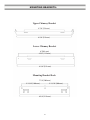
Ancona AN-1132 is a range hood designed for general ventilating use. It features a 30-inch width, making it suitable for use over most standard-sized cooktops. The range hood has three fan speeds, allowing you to adjust the airflow to your needs. It also has a built-in light, providing illumination for your cooking surface. The Ancona AN-1132 is constructed from stainless steel, making it durable and easy to clean. It comes with all the necessary hardware for installation, including a chimney extension for ceiling heights up to 10 feet.
Ancona AN-1132 is a range hood designed for general ventilating use. It features a 30-inch width, making it suitable for use over most standard-sized cooktops. The range hood has three fan speeds, allowing you to adjust the airflow to your needs. It also has a built-in light, providing illumination for your cooking surface. The Ancona AN-1132 is constructed from stainless steel, making it durable and easy to clean. It comes with all the necessary hardware for installation, including a chimney extension for ceiling heights up to 10 feet.


-
 1
1
-
 2
2
-
 3
3
-
 4
4
-
 5
5
-
 6
6
-
 7
7
-
 8
8
-
 9
9
-
 10
10
-
 11
11
-
 12
12
-
 13
13
-
 14
14
-
 15
15
-
 16
16
-
 17
17
-
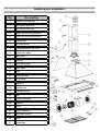 18
18
-
 19
19
-
 20
20
-
 21
21
-
 22
22


Ancona AN-1132 is a range hood designed for general ventilating use. It features a 30-inch width, making it suitable for use over most standard-sized cooktops. The range hood has three fan speeds, allowing you to adjust the airflow to your needs. It also has a built-in light, providing illumination for your cooking surface. The Ancona AN-1132 is constructed from stainless steel, making it durable and easy to clean. It comes with all the necessary hardware for installation, including a chimney extension for ceiling heights up to 10 feet.
Ask a question and I''ll find the answer in the document
Finding information in a document is now easier with AI
Related papers
-
Ancona AN-1132 Installation guide
-
-
Ancona AN-1362 User manual
-
-
-
-
-
-
-
Other documents
-
Cavaliere AirPRO 238 Professional User manual
-
-
-
-
Verona VEHOOD36CH Installation guide
-
-
 Hallman AP238PS6330 Hallman Installation Guide and Users Manual
-
-
-
