5
Important Information
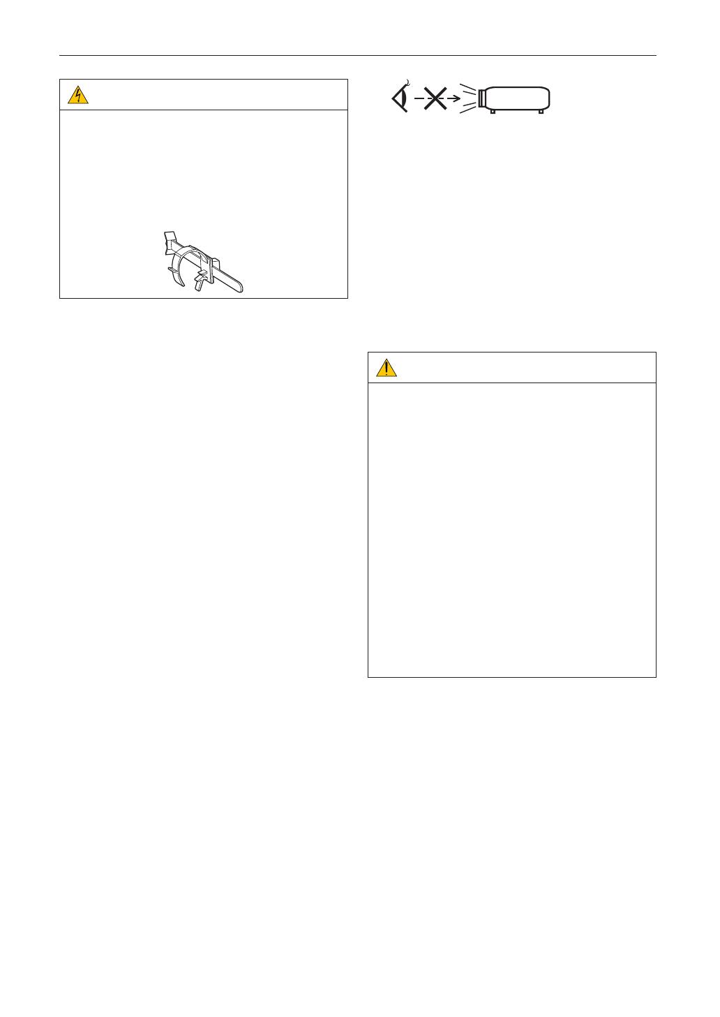
CAUTION:
The power cable stopper (shown in below) is supplied with
this projector.
To prevent the power cable from coming loose, make sure
that all the prongs of the power cable are fully inserted into
the AC IN terminal of the projector before using the power
cable stopper to fix the power cable. A loose contact of the
power cable may cause a fire or electric shock. For using
the power cable stopper, refer to the user’s manual.
Fire and Shock Precautions
1. Ensure that there is sufficient ventilation and that vents are
unobstructed to prevent potentially dangerous concentra-
tions of ozone and the build-up of heat inside your projec-
tor. Allow at least 12 inches (30cm) of space between your
projector and a wall. In particular, clear a space of 27.6
inches (70 cm) or more in front of the air outlet on the rear
surface and 19.8 inches (50 cm) or more in front of the air
outlet on the lamp side. (See page 16)
2. Prevent foreign objects such as paper clips and bits of
paper from falling into your projector. Do not attempt to
retrieve any objects that might fall into your projector. Do
not insert any metal objects such as a wire or screwdriver
into your projector. If something should fall into your projec-
tor, disconnect it immediately and have the object removed
by a qualified service person.
3. Turn off the projector, unplug the power cable and have the
projector serviced by a qualified service personnel under
the following conditions:
• When the power cable or plug is damaged or frayed.
• If liquid has been spilled into the projector, or if it has
been exposed to rain or water.
• If the projector does not operate normally when you fol-
low the instructions described in this user’s manual.
• If the projector has been dropped or the cabinet has
been damaged.
• If the projector exhibits a distinct change in performance,
indicating a need for service.
4. Keep any items such as magnifying glass out of the light
path of the projector. The light being projected from the lens
is extensive, therefore any kind of abnormal objects that
can redirect light coming out of the lens, can cause unpre-
dictable outcome such as fire or injury to the eyes.
5. When using a LAN cable:
For safety, do not connect to the connector for peripheral
device wiring that might have excessive Voltage.
6. Do not look into the lens while the projector is on. Serious
damage to your eyes could result.
7. Do not try to touch the air outlets on the projector during
normal projector operation as it is hot.
Cleaning
1. Turn off the projector and unplug the power cable before
cleaning the cabinet or replacing the lamp.
2. Clean the cabinet periodically with a cloth. If heavily soiled,
use a mild detergent. Never use strong detergents or sol-
vents such as alcohol or thinner.
3. Use a blower or lens paper to clean the lens, and be careful
not to scratch or mar the lens.
4. Do not touch the projector or the power plug with wet
hand. Doing so can cause electrical shock or fire.
CAUTION:
1. Do not unplug the power cable from the wall outlet or
projector when the projector is powered on.
Doing so can damage the projector.
• While projecting images
• While cooling after the power is turned off.
(The STATUS indicator LED blinks in orange while the
fan is rotating, and “cooling...” is displayed on the LCD
screen. )
- When using the NP-90MS02: 100 seconds
• During IMB Operation (if the projector is not in standby
state)
2. Do not turn of the AC power for 90 seconds after the
lamp is turned on and while the POWER indicator is blink-
ing green. Doing so could cause premature lamp failure.
3. Use of a wall outlet with a 20 A or more circuit breaker is
recommended.
4. Keep hands away from the lens mounting portion while
the lens shift is in operation. Failure to do so could result
in fingers being pinched between the cabinet and lens
cover.
Caution on Carrying the Projector/Handling the Optional
Lens
When shipping the projector with the lens, remove the lens
before shipping the projector. Always attach the dust
cap to the lens whenever it is not mounted on the projector. The
lens and the lens shift mechanism may encounter damage
caused by improper handling during transportation.


