Indesit TD 640 S (ICE) IX/HA User guide

Type
User guide
TD 640 IX/HA
TD 631 S IX/HA
TD 640 S IX/HA
TD 640 S GH/HA
TD 641 S IX/HA
TD 750 S IX/HA
TD 751 S GH/HA
TQ 640 S GH/HA
TQ 751 S GH/HA
TZ 640 S /HA
TZ 751 S /HA
TQ 751 S IX/HA
TQ 640 S IX/HA
TD 740 S IX/HA
TD 751 S IX/HA
TZ 751 S N/HA
TZ 751 S K/HA
TQ 640K GH/HA
TQ 640K X/HA
TQ 751K X/HA
TQ 751K GH/HA
English
Operating Instructions
HOB
Français
Mode d’emploi
TABLE DE CUISSON
Español
Manual de instrucciones
ENCIMERA
Portuges
Instruções para a utilização
PLANO
Italiano
Istruzioni per l’uso
PIANO
Índice
Instruções para a utilização,1
Advertências,5
Assistência,10
Descrição do aparelho,13
Instalação,46
Início e utilização,50
Precauções e conselhos,51
Manutenção e cuidados,51
Anomalias e soluções,52
Sumario
Manual de instrucciones,1
Advertencias,4
Asistencia,9
Descripción del aparato,12
Instalación,39
Puesta en funcionamiento y uso,43
Precauciones y consejos,44
Mantenimiento y cuidados,44
Anomalías y soluciones,45
Contents
Operating Instructions,1
Warnings,3
Assistance,9
Description of the appliance,11
Installation,23
Start-up and use,27
Precautions and tips,27
Maintenance and care,28
Troubleshooting,29
Sommaire
Mode d’emploi,1
Avertissements,4
Assistance,9
Description de l’appareil,12
Installation,30
Mise en marche et utilisation,36
Précautions et conseils,37
Nettoyage et entretien,37
Anomalies et remèdes,38
Sommario
Istruzioni per l’uso,1
Avvertenze,3
Assistenza,9
Descrizione dell’apparecchio,11
Installazione,16
Avvio e utilizzo,20
Precauzioni e consigli,20
Manutenzione e cura,21
Anomalie e rimedi,22
3
Avvertenze
ATTENZIONE: Questo apparecchio e le
sue parti accessibili diventano molto caldi
durante l’uso. Bisogna fare attenzione ed
evitare di toccare gli elementi riscaldanti.
Tenere lontani i bambini inferiori agli 8
anni se non continuamente sorvegliati.
Il presente apparecchio può essere
utilizzato dai bambini a partire dagli 8
anni e da persone con ridotte capacità
siche, sensoriali o mentali oppure con
mancanza di esperienza e di conoscenza
se si trovano sotto adeguata sorveglianza
oppure se sono stati istruiti circa l’uso
dell’apparecchio in modo sicuro e se
si rendono conto dei pericoli correlati.
I bambini non devono giocare con
l’apparecchio. Le operazioni di pulizia
e di manutenzione non devono essere
effettuate dai bambini senza sorveglianza.
ATTENZIONE: Lasciare un fornello
incustodito con grassi e olii può essere
pericoloso e può provocare un incendio.
Non bisogna MAI tentare di spegnere
una amma/incendio con acqua, bensì
bisogna spegnere l’apparecchio e coprire
la amma per esempio con un coperchio
o con una coperta ignifuga.
ATTENZIONE: Rischio di incendio: non
lasciare oggetti sulle superci di cottura.
Non utilizzare mai pulitori a vapore o ad alta
pressione per la pulizia dell’apparecchio.
Eliminare eventuali liquidi presenti sul
coperchio prima di aprirlo. Non chiudere
il coperchio in vetro (se presente) con i
bruciatori gas o la piastra elettrica ancora
caldi.
L’apparecchio non è destinato a essere
messo in funzione per mezzo di un
temporizzatore esterno oppure di un
sistema di comando a distanza separato.
ATTENZIONE: l’uso di protezioni del
piano inappropriate può causare incidenti.
Warnings
WARNING: The appliance and its
accessible parts become hot during use.
Care should be taken to avoid touching
heating elements. Children less than 8
years of age shall be kept away unless
continuously supervised. This appliance
can be used by children aged from 8 years
and above and persons with reduced
physical, sensory or mental capabilities
or lack of experience and knowledge
if they have been given supervision
or instruction concerning use of the
appliance in a safe way and understand
the hazards involved. Children shall not
play with the appliance. Cleaning and
user maintenance shall not be made by
children without supervision.
WARNING: Unattended cooking on a hob
with fat or oil can be dangerous and may
result in re. NEVER try to extinguish a
re with water, but switch off the appliance
and then cover ame e.g. with a lid or a
re blanket.
WARNING: Danger of re: do not store
items on the cooking surfaces.
Never use steam cleaners or pressure
cleaners on the appliance.
Remove any liquid from the lid before
opening it. Do not close the glass cover (if
present) when the gas burners or electric
hotplates are still hot.
11
Descrizione dell’apparecchio
Vista d’insieme
1. Griglie di appoggio per RECIPIENTI DI COTTURA
2. BRUCIATORI GAS
3. PIASTRA ELETTRICA*
4. Spia FUNZIONAMENTO PIASTRA ELETTRICA*
5. Manopole di comando dei BRUCIATORI GAS
6. Manopola di comando della PIASTRA ELETTRICA*
7. Candela di accensione dei BRUCIATORI GAS*
8. DISPOSITIVO DI SICUREZZA*
PIASTRE ELETTRICHE possono essere di vari diametri
e potenze diverse: “normali” o “rapide”, quest’ ultime si
riconoscono dalle altre per la presenza di un bollo rosso
al centro.
Spia FUNZIONAMENTO PIASTRA ELETTRICA si
accende per qualsiasi posizione della manopola diversa
da quella di spento
BRUCIATORI GAS sono di diverse dimensioni e potenze.
Scegliete quello più adatto al diametro del recipiente da
utilizzare.
• Manopole di comando dei BRUCIATORI GAS e della
PIASTRA ELETTRICA* per la regolazione della amma
o della potenza.
• Candela di accensione dei BRUCIATORI GAS* permette
l’accensione automatica del bruciatore prescelto.
DISPOSITIVO DI SICUREZZA* in caso di spegnimento
accidentale della amma, interrompe l’uscita del gas.
* Presente solo in alcuni modelli.
Description of the appliance
Overall view
1. Support Grid for COOKWARE
2. GAS BURNERS
3. ELECTRIC HOTPLATE*
4. Electric HOTPLATE INDICATOR LIGHT*
5. Control Knobs for GAS BURNERS
6. Control Knobs for ELECTRIC HOTPLATES*
7. Ignition for GAS BURNERS*
8. SAFETY DEVICES*
ELECTRIC HOTPLATES may have different diameters
and operate at different power levels. These power
levels may be “normal” or “rapid” (the latter may be
distinguished from the others by a red spot in the middle
of the hotplate).
The ELECTRIC HOTPLATE INDICATOR LIGHT
switches on whenever the selector knob is moved from
the ‘off’ position.
GAS BURNERS differ in size and power. Use the
diameter of the cookware to choose the most appropriate
burner to cook with.
Control Knobs for GAS BURNERS and ELECTRIC
PLATES*
GAS BURNER IGNITION* enables a specic burner to
be lit automatically.
SAFETY DEVICE* stops the gas ow if the ame is
accidentally extinguished.
* Only available on certain models.
8
7
1
2
5
2
1
3
4
56
IT
19
Caratteristiche dei bruciatori ed ugelli
Tabella 1 Gas Liquido Gas Naturale
Nominale (mbar)
Minima (mbar)
Massima (mbar)
37
25
45
28-30
20
35
20
17
25
Rapido (R)
Rapido Ridotto (RR)
Ultra Rapido (UR)
Semi Rapido (S)
Ausiliario (A)
Mini WOK (MW)
Pressioni
di
alimentazione
Bruciatore
Diametro
(mm)
Potenza termica
kW (p.c.s.*)
100
100
100
75
55
110
3.00
2.60
3.40
1.65
1.00
3.50
Nomin. Ridot.
0.70
0.70
0.40
0.40
0.40
1.50
By-pass
1/100 (mm)
41
41
41
30
30
(1)
39
39
39
28
28
61
Ugello
1/100
Portata*
g/h
(mm) ***
86
80
91
64
50
91
Ugello
1/100
Portata*
l/h
(mm)
116
110
123
96
79
138
286
248
324
157
95
333
218
189
247
120
73
254
**
214
186
243
118
71
250
* A 15°C e 1013 mbar-gas secco
** Propano P.C.S. = 50.37 MJ/Kg
*** Butano P.C.S. = 49.47 MJ/Kg
Naturale P.C.S. = 37.78 MJ/m
3
(1) Solo per apparecchi con dispositivo di sicurezza contro le fughe di gas.
Ø 145
S
RS
A
S
RS
A
S
RR MW
A
UR
RR
S
S
A
MW
RR
S
S
TD 750 S IX/HA
TD 751 S GH/HA
TQ 751 S GH/HA
TQ 751 S IX/HA
TZ 751 S /HA
TD 751 S IX/HA
TZ 751 S N/HA
TZ 751 S K/HA
TQ 751K X/HA
TQ 751K GH/HA
TD 640 IX/HA
TD 640 S GH/HA
TD 640 S IX/HA
TQ 640 S GH/HA
TQ 640 S IX/HA
TZ 640 S /HA
TQ 640K GH/HA
TQ 640K X/HA
A
S
RS
TD 740 S IX/HA
TD 641 S IX/HA TD 631 S IX/HA
GB
23
Installation
! Before operating your new appliance please read this
instruction booklet carefully. It contains important information
for safe use, installation and care of the appliance.
! Please keep these operating instructions for future reference.
Pass them on to possible new owners of the appliance.
Positioning
! Keep packaging material out of the reach of children. It can
become a choking or suffocation hazard (see Precautions
and tips).
! The appliance must be installed by a qualied professional
according to the instructions provided. Incorrect installation
may cause harm to people and animals or may damage
property.
! This unit may be installed and used only in permanently
ventilated rooms in accordance with British Standard
Codes Of Practice: B.S. 6172 / B.S. 5440, Par. 2 and B.S.
6891 Current Editions. The following requirements must
be observed:
The room must be equipped with an air extraction system
that expels any combustion fumes. This may consist of
a hood or an electric fan that automatically starts each
time the appliance is switched on.
In a chimney stack or branched flue.
(exclusively for cooking appliances)
Directly to
the Outside
The room must also allow proper air circulation, as air is
needed for combustion to occur normally. The ow of air
must not be less than 2 m
3
/h per kW of installed power.
The air circulation system may
take air directly from the outside
by means of a pipe with an inner
cross section of at least 100 cm
2
;
the opening must not be vulnerable
to any type of blockages.
The system can also provide the air
needed for combustion indirectly,
i.e. from adjacent rooms tted with
air circulation tubes as described
above. However, these rooms must
not be communal rooms, bedrooms
or rooms that may present a re
hazard.
A
Examples of
ventilation holes
for comburant air.
Enlarging the ventilation slot
between window and floor.
Adjacent
Room
Room to be
Vented
Liquid petroleum gas sinks to the oor as it is heavier
than air. Therefore, rooms containing LPG cylinders must
also be equipped with vents to allow gas to escape in
the event of a leak. As a result LPG cylinders, whether
partially or completely full, must not be installed or stored
in rooms or storage areas that are below ground level
(cellars, etc.). It is advisable to keep only the cylinder
being used in the room, positioned so that it is not subject
to heat produced by external sources (ovens, replaces,
stoves, etc. ) which could raise the temperature of the
cylinder above 50°C.
Fitting the appliance
The following precautions must be taken when installing
the hob:
Kitchen cabinets adjacent to the appliance and taller than
the top of the hob must be at least 600 mm from the edge
of the hob (see gure).
Hoods must be installed according to their relative
installation instruction manuals and at a minimum
distance of 650 mm from the hob.
Place the wall cabinets adjacent to the hood at a minimum
height of 420 mm from the hob (see gure).
If the hob is installed beneath a wall
cabinet, the latter must be situated
at a minimum of 700 mm above
the hob.
The installation cavity should have the dimensions
indicated in the gure.
Fastening hooks are provided, allowing you to fasten
the hob to tops that are between 20 and 40 mm thick.
To ensure the hob is securely fastened to the top, we
recommend you use all the hooks provided.
555 mm
55 mm
475 mm
Before fastening the cooktop in place, position the seal
(supplied) along the perimeter of the countertop, as
shown in the gure.
600mm min.
420mm min.
650mm min.
24
GB
Hook fastening diagram
Hooking position Hooking position
for top H=20mm for top H=30mm
Front
Hooking position Back
for top H=40mm
! Use the hooks contained in the “accessory pack”.
Where the hob is not installed over a built-in oven, a
wooden panel must be installed as insulation. This must
be placed at a minimum distance of 20 mm from the lower
part of the hob.
Ventilation
To ensure adequate ventilation, the back panel of the cabinet
must be removed. It is advisable to install the oven so that it
rests on two strips of wood, or on a completely at surface
with an opening of at least 45 x 560 mm (see diagrams).
560 mm.
45 mm.
! The hob can only be installed above built-in ovens with a
cooling ventilation system.
Electrical connection
Hobs equipped with a three-pole power supply cable are
designed to operate with alternating current at the voltage
and frequency indicated on the data plate (this is located
on the lower part of the appliance). The earth wire in the
cable has a green and yellow cover. If the appliance is to
be installed above a built-in electric oven, the electrical
connection of the hob and the oven must be carried out
separately, both for electrical safety purposes and to make
extracting the oven easier.
Connecting the supply cable to the mains
Install a standardised plug corresponding to the load
indicated on the data plate.
The appliance must be directly connected to the mains
using an omnipolar circuit-breaker with a minimum contact
opening of 3 mm installed between the appliance and the
mains. The circuit-breaker must be suitable for the charge
indicated and must comply with current electrical regulations
(the earthing wire must not be interrupted by the circuit-
breaker). The supply cable must not come into contact with
surfaces with temperatures higher than 50°C.
! The installer must ensure that the correct electrical
connection has been made and that it is compliant with
safety regulations.
Before connecting to the power supply, make sure that:
The appliance is earthed and the plug is compliant with
the law.
The socket can withstand the maximum power of the
appliance, which is indicated on the data plate.
The voltage is in the range between the values indicated
on the data plate.
The socket is compatible with the plug of the appliance.
If the socket is incompatible with the plug, ask an
authorised technician to replace it. Do not use extension
cords or multiple sockets.
! Once the appliance has been installed, the power supply
cable and the electrical socket must be easily accessible.
! The cable must not be bent or compressed.
! The cable must be checked regularly and replaced by
authorised technicians only (see Assistance).
! The manufacturer declines any liability should these safety
measures not be observed.
Gas connection
The appliance should be connected to the main gas supply
or to a gas cylinder in compliance with current national
regulations. Before carrying out the connection, make sure
the cooker is compatible with the gas supply you wish to
use. If this is not the case, follow the instructions indicated
in the paragraph “Adapting to different types of gas.”
When using liquid gas from a cylinder, install a pressure
regulator which complies with current national regulations.
! Check that the pressure of the gas supply is consistent
with the values indicated in Table 1 (“Burner and nozzle
specications”). This will ensure the safe operation and
longevity of your appliance while maintaining efcient
energy consumption.
Connection with a rigid pipe (copper or steel)
! Connection to the gas system must be carried out in such a
way as not to place any strain of any kind on the appliance.
There is an adjustable L-shaped pipe tting on the appliance
supply ramp and this is tted with a seal in order to prevent
leaks. The seal must always be replaced after rotating the
GB
25
pipe tting (seal provided with appliance). The gas supply
pipe tting is a threaded 1/2 gas cylindrical male attachment.
Connecting a exible jointless stainless steel pipe to a
threaded attachment
The gas supply pipe tting is a threaded 1/2 gas cylindrical
male attachment.
These pipes must be installed so that they are never longer
than 2000 mm when fully extended. Once connection has
been carried out, make sure that the exible metal pipe
does not touch any moving parts and is not compressed.
! Only use pipes and seals that comply with current national
regulations.
Checking the tightness of the connection
! When the installation process is complete, check the pipe
ttings for leaks using a soapy solution. Never use a ame.
Adapting to different types of gas
To adapt the hob to a different type of gas other than default
type (indicated on the rating plate at the base of the hob or
on the packaging), the burner nozzles should be replaced
as follows:
1. Remove the hob grids and slide the burners off their
seats.
2. Unscrew the nozzles using a 7 mm socket spanner, and
replace them with nozzles for the new type of gas (see
table 1 “Burner and nozzle characteristics”).
In the case of the Mini WOK burner,
use a spanner with a 7 mm opening
to unscrew the nozzle (see gure).
3. Reassemble the parts following the above procedure in
the reverse order.
4. Once this procedure is nished, replace the old rating
sticker with one indicating the new type of gas used.
Sticker are available from any of our Service Centres.
Adjusting the burners’ primary air
Does not require adjusting.
Setting the burners to minimum
1. Turn the tap to the low ame position;
2. Remove the knob and adjust the adjustment screw, which
is positioned in or next to the tap pin, until the ame is
small but steady.
3. Having adjusted the ame to the required low setting,
while the burner is alight, quickly change the position
of the knob from minimum to maximum and vice versa
several times, checking that the ame does not go out.
4. Some appliances have a safety device (thermocouple)
tted. If the device fails to work when the burners are set
to the low ame setting, increase this low ame setting
using the adjusting screw.
5. Once the adjustment has been made, replace the seals on
the by-passes using sealing wax or a similar substance.
! If the appliance is connected to liquid gas, the regulation
screw must be fastened as tightly as possible.
! Once this procedure is nished, replace the old rating
sticker with one indicating the new type of gas used. Stickers
are available from any of our Service Centres.
! Should the gas pressure used be different (or vary slightly)
from the recommended pressure, a suitable pressure
regulator must be tted to the inlet pipe (in order to comply
with current national regulations).
Electrical
connections
DATA PLATE
see data plate
This appliance conforms to the following
European Economic Community directives:
- 2006/95/EEC dated 12/12/06 (Low
Voltage) and subsequent amendments
- 2004/108/EEC dated 15/12/04
(Electromagnetic Compatibility) and
subsequent amendments
- 93/68/EEC dated 22/07/93 and
subsequent amendments.
- 2009/142/EEC dated 30/11/09 (Gas) and
subsequent amendments.
- 2012/19/EC and subsequent
amendments.
26
GB
Burner and nozzle specications
Table 1 Liquid Gas Naturale Gas
Nominal (mbar)
Minimum (mbar)
Maximum (mbar)
20
17
25
28-30
20
35
37
25
45
Fast (R)
Reduced Fast (RR)
Ultra Rapid (UR)
Semi Fast (S)
Auxiliary (A)
Mini WOK (MW)
Supply pressures
Burner
Diameter
(mm)
Thermal Power
kW (p.c.s.*)
100
100
100
75
55
110
3.00
2.60
3.40
1.65
1.00
3.50
Nomin. Reduc.
0.70
0.70
0.70
0.40
0.40
1.50
By-pass
1/100 (mm)
41
41
41
30
30
(1)
39
39
39
28
28
61
Nozzle
1/100
Flow*
g/h
(mm) ***
86
80
91
64
50
91
Nozzle
1/100
Flow*
l/h
(mm)
116
110
123
96
79
138
286
248
324
157
95
333
218
189
247
120
73
254
**
214
186
243
118
71
250
* At 15°C and 1013 mbar - dry gas
** Propane P.C.S. = 50.37 MJ/Kg
*** Butane P.C.S. = 49.47 MJ/Kg
Natural P.C.S. = 37.78 MJ/m
3
(1) Only for appliances with the security device.
Ø 145
S
RS
A
S
RS
A
S
RR MW
A
UR
RR
S
S
A
MW
RR
S
S
TD 750 S IX/HA
TD 751 S GH/HA
TQ 751 S GH/HA
TQ 751 S IX/HA
TZ 751 S /HA
TD 751 S IX/HA
TZ 751 S N/HA
TZ 751 S K/HA
TQ 751K X/HA
TQ 751K GH/HA
TD 640 IX/HA
TD 640 S GH/HA
TD 640 S IX/HA
TQ 640 S GH/HA
TQ 640 S IX/HA
TZ 640 S /HA
TQ 640K GH/HA
TQ 640K X/HA
A
S
RS
TD 740 S IX/HA
TD 641 S IX/HA TD 631 S IX/HA
GB
27
Start-up and use
! The position of the corresponding gas burner or electric
hotplate* is shown on every knob.
Gas burners
Each burner can be adjusted to one of the following settings
using the corresponding control knob:
Off
Maximum
Minimum
To light one of the burners, hold a lit match or lighter near
the burner and, at the same time, press down and turn the
corresponding knob anti-clockwise to the maximum setting.
Since the burner is tted with a safety device, the knob
should be pressed for approximately 6 seconds to allow
the automatic device keeping the ame alight to heat up.
When using models with an ignition button, light the desired
burner by rst pressing the gas burners button (identiable
by the symbol), then pressing down the corresponding
knob as far as possible and turning it anticlockwise towards
the maximum setting.
Some models are equipped with an ignition button
incorporated into the control knob. If this is the case, the
ignitor is present, but not the button.
To light a burner, simply press the corresponding knob all the
way in and then turn it in the counter-clockwise direction to
the “High” setting, keeping it pressed in until the burner lights.
! If a ame is accidentally extinguished, turn off the control
knob and wait for at least 1 minute before trying to relight it.
To switch off the burner, turn the knob in a clockwise
direction until it stops (when reaches the “●” position).
Electric hotplates*
The corresponding knob may be turned clockwise or anti-
clockwise and set to six different positions:
Setting Normal o Fast Plate
0 Off
1
Low
2-5 Medium
6 High
When the selector knob is in any position other than the off
position, the ‘on’ light comes on.
Practical advice on using the burners
To ensure the burners operate efciently:
Use appropriate cookware for each burner (see table)
so that the ames do not extend beyond the bottom of
the cookware.
Always use cookware with a at base and a cover.
When the contents of the pan reach boiling point, turn
the knob to minimum.
Burner
Rapid (R)
Reduced Rapid (RR)
Ultra Rapid (UR)
Semi-Rapid (S)
Auxiliary (A)
Mini WOK (MW)
Ø Cookware Diameter (cm)
24 - 26
24 - 26
24 - 26
16 - 20
10 - 14
24 - 26
To identify the type of burner, refer to the designs in the
section entitled, “Burner and Nozzle Specications”.
Practical advice on using the electric
hotplates*
To avoid heat loss and damage to the hotplates, use pans
with a at base, whose diameter is no less than that of the
hotplate itself.
Setting
0
1
2
3
4
5
6
Setting
Off
Cooking vegetables, fish
Cooking patatoes (using steam) soups,
chickpeas, beans.
Continuing the cooking of large quantities of
food, minestrone.
For roasting (average)
For roasting (above average)
For browning and reaching a boil in a short time
! Before using the hotplates for the rst time, you should heat
them at maximum temperature for approximately 4 minutes,
without placing any pans on them. During this initial stage, their
protective coating hardens and reaches its maximum resistance.
Precautions and tips
! This appliance has been designed and manufactured
in compliance with international safety standards. The
following warnings are provided for safety reasons and
must be read carefully.
* Only available on certain models.
28
GB
General safety
This is a class 3 built-in appliance.
Gas appliances require regular air exchange to
maintain efcient operation. When installing the hob,
follow the instructions provided in the paragraph on
“Positioning” the appliance.
These instructions are only valid for the countries
whose symbols appear in the manual and on the serial
number plate.
The appliance was designed for domestic use inside the
home and is not intended for commercial or industrial
use.
The appliance must not be installed outdoors, even in
covered areas. It is extremely dangerous to leave the
appliance exposed to rain and storms.
Do not touch the appliance with bare feet or with wet or
damp hands and feet.
The appliance must be used by adults only for the
preparation of food, in accordance with the instructions
outlined in this booklet. Any other use of the appliance
(e.g. for heating the room) constitutes improper use and
is dangerous. The manufacturer may not be held liable
for any damage resulting from improper, incorrect and
unreasonable use of the appliance.
Ensure that the power supply cables of other electrical
appliances do not come into contact with the hot parts
of the oven.
The openings used for ventilation and dispersion of heat
must never be covered.
Always make sure the knobs are in the “●”/“” position
when the appliance is not in use.
When unplugging the appliance always pull the plug from
the mains socket, do not pull on the cable.
Never carry out any cleaning or maintenance work
without having detached the plug from the mains.
In case of malfunction, under no circumstances should
you attempt to repair the appliance yourself. Repairs
carried out by inexperienced persons may cause injury
or further malfunctioning of the appliance. Contact a
Service Centre (see Assistance).
Always make sure that pan handles are turned towards
the centre of the hob in order to avoid accidental burns.
Do not close the glass cover (if present) when the gas
burners or electric hotplates are still hot.
Do not leave the electric hotplate switched on without a
pan placed on it.
Do not use unstable or deformed pans.
The appliance should not be operated by people
(including children) with reduced physical, sensory or
mental capacities, by inexperienced individuals or by
anyone who is not familiar with the product. These
individuals should, at the very least, be supervised by
someone who assumes responsibility for their safety or
receive preliminary instructions relating to the operation
of the appliance.
Do not let children play with the appliance.
The appliance is not intended to be operated by means
of an external timer or separate remote-control system.
Disposal
When disposing of packaging material: observe local
legislation so that the packaging may be reused.
The European Directive 2012/19/EC on Waste
Electrical and Electronic Equipment (WEEE), requires
that old household electrical appliances must not
be disposed of in the normal unsorted municipal
waste stream. Old appliances must be collected
separately in order to optimise the recovery and
recycling of the materials they contain and reduce
the impact on human health and the environment.
The crossed out “wheeled bin” symbol on the product
reminds you of your obligation, that when you dispose
of the appliance it must be separately collected.
Consumers should contact their local authority or retailer
for information concerning the correct disposal of their
old appliance.
Maintenance and care
Switching the appliance off
Disconnect your appliance from the electricity supply before
carrying out any work on it.
Cleaning the appliance
! Do not use abrasive or corrosive detergents such as stain
removers, anti-rust products, powder detergents or sponges with
abrasive surfaces: these may scratch the surface beyond repair.
! Never use steam cleaners or pressure cleaners on the
appliance.
• It is usually enough to wash the hob with a damp sponge
and dry it with absorbent kitchen roll.
The removable parts of the burners should be washed
frequently with warm water and soap and any burnt-on
substances removed.
For hobs which ligth automatically, the terminal part of
the electronic instant lighting devices should be cleaned
frequently and the gas outlet holes should be checked
for blockages.
Stainless steel can be marked by hard water that has
been left on the surface for a long time, or by aggressive
detergents containing phosphorus. After cleaning, rinse
and dry any remaining drops of water.
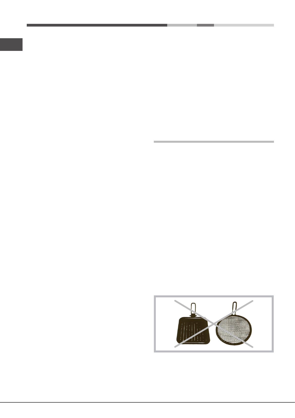
! Do not use stainless steel ame spreaders, bread
toasters or meat grills over gas ames.
GB
29
Gas tap maintenance
Over time, the taps may become jammed or difcult to turn.
If this happens, the tap must be replaced.
! This procedure must be performed by a qualied
technician authorised by the manufacturer.
Troubleshooting
It may happen that the appliance does not function properly
or at all. Before calling the service centre for assistance,
check if anything can be done. First, check to see that there
are no interruptions in the gas and electrical supplies, and,
in particular, that the gas valves for the mains are open.
The burner does not light or the ame is not even
around the burner.
Check whether:
The gas holes on the burner are clogged.
All the movable parts that make up the burner are
mounted correctly.
There are draughts near the appliance.
The ame dies in models with a safety device.
Check to make sure that:
You pressed the knob all the way in.
You keep the knob pressed in long enough to activate
the safety device.
The gas holes are not blocked in the area corresponding
to the safety device.
The burner does not remain lit when set to minimum.
Check to make sure that:
The gas holes are not blocked.
There are no draughts near the appliance.
The minimum setting has been adjusted properly.
The cookware is unstable.
Check to make sure that:
The bottom of the cookware is perfectly at.
The cookware is positioned correctly at the centre of the
burner.
The pan support grids have been positioned correctly.
FR
BE
LU
NL
35
Gaz NaturelsTableau 1 (Pour la Hollande)
Brûleur
Rapide (R)
Rapide Réduit (RR)
Ultra Rapide (UR)
Semi Rapide (S)
Auxiliaire (A)
Mini WOK (MW)
Pression
de
alimentation
Débit*
(l/h)
G25
332
288
376
183
111
365
25
20
30
Diamêtre
(mm)
100
100
100
75
55
110
Nominal
3.00
2.60
3.40
1.65
1.00
3.50
Réduit
0.70
0.70
0.70
0.40
0.40
1.50
Puissance thermique
kW (p.c.s.*)
Injecteur
1/100
(mm)
116
110
123
96
79
138
Nominale (mbar)
Minimum (mbar)
Maximum (mbar)
* A 15°C et 1013 mbar-gaz sec
** Propane P.C.S. = 50.37 MJ/Kg
*** Butane P.C.S. = 49.47 MJ/Kg
Naturel G20 P.C.S. = 37.78 MJ/m
3
Naturel G25 P.C.S. = 32.49 MJ/m
3
(1) Seulement pour les appareils équipés de dispositif de sécurité.
(2) Voir la plaquette d’immatriculation de l’appareil.
Ø 145
S
RS
A
S
RS
A
S
RR MW
A
UR
RR
S
S
A
MW
RR
S
S
TD 750 S IX/HA
TD 751 S GH/HA
TQ 751 S GH/HA
TQ 751 S IX/HA
TZ 751 S /HA
TD 751 S IX/HA
TZ 751 S N/HA
TZ 751 S K/HA
TQ 751K X/HA
TQ 751K GH/HA
TD 640 IX/HA
TD 640 S GH/HA
TD 640 S IX/HA
TQ 640 S GH/HA
TQ 640 S IX/HA
TZ 640 S /HA
TQ 640K GH/HA
TQ 640K X/HA
A
S
RS
TD 740 S IX/HA
TD 641 S IX/HA TD 631 S IX/HA
42
ES
Características de los quemadores e inyectores
Tabla 1 Gas Liquido Gas Natural
Nominal (mbar)
Minimo (mbar)
Màximo (mbar)
37
25
45
28-30
20
35
20
17
25
Ràpido (R)
Ràpido Reducido (RR)
Ultrarrápido (UR)
Semi Ràpido (S)
Auxiliar (A)
Mini WOK (MW)
Presiones
de
suministro
Quemador
Diametro
(mm)
Potencia térmica
kW (p.c.s.*)
100
100
100
75
55
110
3.00
2.60
3.40
1.65
1.00
3.50
Nomin. Reduc.
0.70
0.70
0.40
0.40
0.40
1.30
By-pass
1/100 (mm)
41
41
41
30
30
(1)
39
39
39
28
28
57
Pico
1/100
Capacid.*
g/h
(mm) ***
86
80
91
64
50
91
Pico
1/100
Capacid.*
l/h
(mm)
116
110
123
96
79
138
286
248
324
157
95
333
218
189
247
120
73
254
**
214
186
243
118
71
250
* A 15°C y 1013 mbar-gas seco
** Propano P.C.S. = 50.37 MJ/Kg
*** Butano P.C.S. = 49,47 MJ/Kg
Natural P.C.S. = 37.78 MJ/m
3
Ciudad P.C.S. = 15.87 MJ/m
3
(1) Únicamente para aquellos aparatos con dispositivos de seguridad contra fugas de gas.
Ø 145
S
RS
A
S
RS
A
S
RR MW
A
UR
RR
S
S
A
MW
RR
S
S
TD 750 S IX/HA
TD 751 S GH/HA
TQ 751 S GH/HA
TQ 751 S IX/HA
TZ 751 S /HA
TD 751 S IX/HA
TZ 751 S N/HA
TZ 751 S K/HA
TQ 751K X/HA
TQ 751K GH/HA
TD 640 IX/HA
TD 640 S GH/HA
TD 640 S IX/HA
TQ 640 S GH/HA
TQ 640 S IX/HA
TZ 640 S /HA
TQ 640K GH/HA
TQ 640K X/HA
A
S
RS
TD 740 S IX/HA
TD 641 S IX/HA TD 631 S IX/HA
49
PT
Características dos queimadores e bicos
Tabla 1 Gás Liquefeito Gás Natural
Nominal (mbar)
Minima (mbar)
Màxima (mbar)
37
25
45
28-30
20
35
20
17
25
Ràpido (R)
Ràpido Reduz. (RR)
Ultra-Rápido (UR)
Semi Ràpido (S)
Auxiliar (A)
Mini WOK (MW)
Pressões
de
alimentação
Queimador
Diâmetro
(mm)
Poténcia térmica
kW (p.c.s.*)
100
100
100
75
55
110
3.00
2.60
3.40
1.65
1.00
3.50
Nomin. Reduz.
0.70
0.70
0.40
0.40
0.40
1.50
By-pass
1/100 (mm)
41
41
41
30
30
(1)
39
39
39
28
28
61
Bico
1/100
Capacid.*
g/h
(mm) ***
86
80
91
64
50
91
Bico
1/100
Capacid.*
l/h
(mm)
116
110
123
96
79
138
286
248
324
157
95
333
218
189
247
120
73
254
**
214
186
243
118
71
250
* A 15°C e 1013 mbars-gás seco
** Propano P.C.S. = 50,37 MJ/Kg.
*** Butano P.C.S. = 49,47 MJ/Kg.
Natural P.C.S. = 37,78 MJ/m
3
(1) Únicamente para aquellos aparatos con dispositivos de seguridad contra fugas de gas
Ø 145
S
RS
A
S
RS
A
S
RR MW
A
UR
RR
S
S
A
MW
RR
S
S
TD 750 S IX/HA
TD 751 S GH/HA
TQ 751 S GH/HA
TQ 751 S IX/HA
TZ 751 S /HA
TD 751 S IX/HA
TZ 751 S N/HA
TZ 751 S K/HA
TQ 751K X/HA
TQ 751K GH/HA
TD 640 IX/HA
TD 640 S GH/HA
TD 640 S IX/HA
TQ 640 S GH/HA
TQ 640 S IX/HA
TZ 640 S /HA
TQ 640K GH/HA
TQ 640K X/HA
A
S
RS
TD 740 S IX/HA
TD 641 S IX/HA TD 631 S IX/HA
57
BE
Merkmale der Brenner und Düsen
Tabelle 1
Nominal (mbar)
Minimum (mbar)
Maximum (mbar)
28-30
20
35
37
25
45
Starkbrenner (R)
Reduz. Starkbrenner (RR)
Schnellbrenner (UR)
Mittelstarker Brenner (S)
Hilfsbrenner (A)
Mini WOK (MW)
Versorgungs-druck
Brenner Durch-
messer
(mm)
Wärme-
leistung
kW (p.c.s.*)
100
100
100
75
55
110
3.00
2.60
3.40
1.65
1.00
3.50
Nom.
Wärme-
leistung
kW (p.c.s.*)
3.00
2.60
3.40
1.65
1.00
3.30
Nom.Red.
0.70
0.70
0.70
0.40
0.40
1.50
By-pass
1/100
(mm)
41
41
41
30
30
(1)
39
39
39
28
28
61
Düse
1/100
Menge*
g/h
(mm) Butan
86
80
91
64
50
91
Düse
1/100
Menge*
l/h
Menge*
l/h
(mm)
20
15
25
G20
116
110
123
96
79
138
286
248
324
157
95
333
25
15
30
G25
332
288
376
183
111
365
218
189
247
120
73
254
Propan
214
186
243
118
71
250
Erdgas Flüssiggas
* Bie 15°C und 1013 mbar-Trockengas
Propan P.C.S. = 50,37 MJ/kg
Butan P.C.S. = 49,47 MJ/kg
Erdgas G20 P.C.S. = 37,78 MJ/m³
Erdgas G25 P.C.S. = 32,49 MJ/m³
(1) Nur für Geräte, die mit einer Sicherheitsvorrichtung gegen Gasverluste ausgerüstet sind.
Ø 145
S
RS
A
S
RS
A
S
RR MW
A
UR
RR
S
S
A
MW
RR
S
S
TD 750 S IX/HA
TD 751 S GH/HA
TQ 751 S GH/HA
TQ 751 S IX/HA
TZ 751 S /HA
TD 751 S IX/HA
TZ 751 S N/HA
TZ 751 S K/HA
TQ 751K X/HA
TQ 751K GH/HA
TD 640 IX/HA
TD 640 S GH/HA
TD 640 S IX/HA
TQ 640 S GH/HA
TQ 640 S IX/HA
TZ 640 S /HA
TQ 640K GH/HA
TQ 640K X/HA
A
S
RS
TD 740 S IX/HA
TD 641 S IX/HA TD 631 S IX/HA
NL
BE
65
Natuurlijk gas
Table 1 (Voor Nederland)
Gaspit
Snel (R)
Gered. Snel (RR)
Extra-Snel (UR)
Halp Snel (S)
Hulp (A)
Mini WOK (MW)
Spanning
van
voeding
Bereik*
(l/h)
G25
332
288
376
183
111
365
25
20
30
Doorsnee
(mm)
100
100
100
75
55
110
Nomin.
3.00
2.60
3.40
1.65
1.00
3.50
Gered.
0.70
0.70
0.70
0.40
0.40
1.50
Thermisch vermogen
kW (p.c.s.*)
Straal.
1/100
(mm)
116
110
123
96
79
138
Nominale (mbar)
Minimum (mbar)
Maximum (mbar)
* Met 15°C en 1013 mbar-droog gas
** P.C.S. Propaangas = 50,37 MJ/kg
*** P.C.S. Butangas = 49,47 MJ/kg
P.C.S. Natuurlijk gas G20 = 37,78 MJ/m³
P.C.S. Natuurlijk gas G25 = 32,49 MJ/m³
(1) Allen voor apparaten met veiligheidsmechanisme om gaslekkages te voorkomen.
Ø 145
S
RS
A
S
RS
A
S
RR MW
A
UR
RR
S
S
A
MW
RR
S
S
TD 750 S IX/HA
TD 751 S GH/HA
TQ 751 S GH/HA
TQ 751 S IX/HA
TZ 751 S /HA
TD 751 S IX/HA
TZ 751 S N/HA
TZ 751 S K/HA
TQ 751K X/HA
TQ 751K GH/HA
TD 640 IX/HA
TD 640 S GH/HA
TD 640 S IX/HA
TQ 640 S GH/HA
TQ 640 S IX/HA
TZ 640 S /HA
TQ 640K GH/HA
TQ 640K X/HA
A
S
RS
TD 740 S IX/HA
TD 641 S IX/HA TD 631 S IX/HA
73
PL
Charakterystyki palników oraz dysz
Tabela 1 (dla Polski) GZ 50 GZ 35 GPB-B
S redni (RR)
Duzy (R)
Ultra Duzy (UR)
Pólszybki (sredni) (S)
Pomocniczy (maly) (A)
Mini WOK (MW)
Cisnienia
zasilania
* A 15°C e 1013 mbar - gaz suchy
GZ50 p.c.i. = 35.9 MJ/m
3
GZ35 p.c.i. = 25.8 MJ/m
3
GPB p.c.i. = 123.6 MJ/m
3
16
20
25
10
13
16
Palnik
Moc cieplna
(p.c.i.*) kW
2.50
2.70
2.60
1.60
0.90
3.50
Srednica
1/100 (mm)
minimalne (mbar)
nominalne (mbar)
maksymalne (mbar)
100
100
100
75
55
110
Dysza 1/100
(w mm)
110
116
110
96
71
138
Przeplyw*
l/godz
265
286
248
169
95
333
Dysza 1/100
(w mm)
170
180
171
140
106
195
Przeplyw*
l/godz
368
398
344
236
133
463
29
36
44
Dysza 1/100
(w mm)
80
86
80
64
50
91
Przeplyw*
l/godz
197
213
211
126
71
269
Ø 145
S
RS
A
S
RS
A
S
RR MW
A
UR
RR
S
S
A
MW
RR
S
S
TD 750 S IX/HA
TD 751 S GH/HA
TQ 751 S GH/HA
TQ 751 S IX/HA
TZ 751 S /HA
TD 751 S IX/HA
TZ 751 S N/HA
TZ 751 S K/HA
TQ 751K X/HA
TQ 751K GH/HA
TD 640 IX/HA
TD 640 S GH/HA
TD 640 S IX/HA
TQ 640 S GH/HA
TQ 640 S IX/HA
TZ 640 S /HA
TQ 640K GH/HA
TQ 640K X/HA
A
S
RS
TD 740 S IX/HA
TD 641 S IX/HA TD 631 S IX/HA
UA
81
Характеристики пальників і насадок
Таблиця 1 Зріджений газ Природний газ
Номінальний (мбар)
Мінімальний (мбар)
Максимальний (мбар)
37
25
45
28-30
20
35
20
17
25
Швидка (R)
Зменшеної
швидкості (RR)
Ультрашвидка (UR)
Напівшвидка (S)
Допоміжна (A)
Міні ВОК (MW)
Тиск, що подається
Пальник
Діаметр
(мм)
Теплова
потужність
кВт (p.c.s.*)
100
100
100
75
55
110
3.00
2.60
3.40
1.65
1.00
3.50
Номiн. Зменш.
0.70
0.70
0.40
0.40
0.40
1.50
Перепускний
клапан
1/100 (мм)
41
41
41
30
30
(1)
39
39
39
28
28
61
Форсунка
1/100
Витрати*
г/год
(мм) ***
86
80
91
64
50
91
Форсунка
1/100
Витрати*
г/год
(мм)
116
110
123
96
79
138
286
248
324
157
95
333
218
189
247
120
73
254
**
214
186
243
118
71
250
* При 15°C і 1013 мбар-сухий газ
** Пропан P.C.S. = 49.47 МДж/кг
*** Бутан P.C.S. = 49.47 МДж/кг
Природний газ P.C.S. = 37.78 МДж/м
3
(1) Тільки для плити з засобом безпеки.
Ø 145
S
RS
A
S
RS
A
S
RR MW
A
UR
RR
S
S
A
MW
RR
S
S
TD 750 S IX/HA
TD 751 S GH/HA
TQ 751 S GH/HA
TQ 751 S IX/HA
TZ 751 S /HA
TD 751 S IX/HA
TZ 751 S N/HA
TZ 751 S K/HA
TQ 751K X/HA
TQ 751K GH/HA
TD 640 IX/HA
TD 640 S GH/HA
TD 640 S IX/HA
TQ 640 S GH/HA
TQ 640 S IX/HA
TZ 640 S /HA
TQ 640K GH/HA
TQ 640K X/HA
A
S
RS
TD 740 S IX/HA
TD 641 S IX/HA TD 631 S IX/HA
  • Page 1 1
  • Page 2 2
  • Page 3 3
  • Page 4 4
  • Page 5 5
  • Page 6 6
  • Page 7 7
  • Page 8 8
  • Page 9 9
  • Page 10 10
  • Page 11 11
  • Page 12 12
  • Page 13 13
  • Page 14 14
  • Page 15 15
  • Page 16 16
  • Page 17 17
  • Page 18 18
  • Page 19 19
  • Page 20 20
  • Page 21 21
  • Page 22 22
  • Page 23 23
  • Page 24 24
  • Page 25 25
  • Page 26 26
  • Page 27 27
  • Page 28 28
  • Page 29 29
  • Page 30 30
  • Page 31 31
  • Page 32 32
  • Page 33 33
  • Page 34 34
  • Page 35 35
  • Page 36 36
  • Page 37 37
  • Page 38 38
  • Page 39 39
  • Page 40 40
  • Page 41 41
  • Page 42 42
  • Page 43 43
  • Page 44 44
  • Page 45 45
  • Page 46 46
  • Page 47 47
  • Page 48 48
  • Page 49 49
  • Page 50 50
  • Page 51 51
  • Page 52 52
  • Page 53 53
  • Page 54 54
  • Page 55 55
  • Page 56 56
  • Page 57 57
  • Page 58 58
  • Page 59 59
  • Page 60 60
  • Page 61 61
  • Page 62 62
  • Page 63 63
  • Page 64 64
  • Page 65 65
  • Page 66 66
  • Page 67 67
  • Page 68 68
  • Page 69 69
  • Page 70 70
  • Page 71 71
  • Page 72 72
  • Page 73 73
  • Page 74 74
  • Page 75 75
  • Page 76 76
  • Page 77 77
  • Page 78 78
  • Page 79 79
  • Page 80 80
  • Page 81 81
  • Page 82 82
  • Page 83 83
  • Page 84 84

Indesit TD 640 S (ICE) IX/HA User guide

Type
User guide

Ask a question and I''ll find the answer in the document

Finding information in a document is now easier with AI