
JS4QE-KB & JS6QF Series - Residential Split System Air Conditioner
Table 2. Thermostat Wire Gauge
THERMOSTAT
WIRE GAUGE
RECOMMENDED T-STAT WIRE
UNIT TO T-STAT (LENGTH IN FT)
2-WIRE
(HEATING)
5-WIRE
(HEATING/COOLING)
24 55 25
22 90 45
20 140 70
18 225 110
Table 1. Electrical Specifications & Physical Data
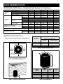
Table 3. Unit Dimensions
MODEL
NUMBER
HEIGHT
(H)
WIDTH
(W)
DEPTH
(D)
JS4QE-024KB 31 1/2" 22 3/4" 22 3/4"
JS4QE-030KB 27 1/2" 30 3/4" 30 3/4"
JS4QE-036KA 35 1/2" 30 3/4" 30 3/4"
JS6QF-042K 43" 30 3/4" 30 3/4"
JS6QF-048K 43" 30 3/4" 30 3/4"
D
W
H
Figure 1. Clearance Requirements
2” Mounting Pad
24" for
Service Access
12" or 18”
See Note
12" or 18”
See Note
DO NOT
OBSTRUCT
TOP OF UNIT
NOTE: Units require full perimeter clearances.
Installer must maintain 18” between two units
or 12” between single unit and structure.
6” from Building
or Structure
48”
QUICK REFERENCE DATA
MODEL NUMBERS: JS4QE-024KB JS4QE-030KB JS4QE-036KA JS6QF-042K JS6QF-048K
Electrical
Data
Volts-Cycles-Phase (1) 208/230-60-1
Total Amps 9.0 10.8 15.1 19.4 22.4
Delay Fuse Max. (2) 15 20 30 40 45
Min. Circuit Ampacity 11.1 13.3 18.6 23.9 27.4
Condenser
Data
Coil
Area 11.7 15.2 20.3 25.3 25.3
Rows-FPI 1-23 1-18 1-18 1-23 1-23
Tube Dia Micro-Channel
Fan Motor
Type PSC BLDC
Amps 0.7 0.9 1.0 1.5 2.6
HP 0.10 0.13 0.20 0.25 0.33
Compressor Data
RLA 8.3 9.9 14.1 17.9 19.8
LRA 50.0 69.0 77.0 112.0 109.0
Refrigerant suction line O.D
NOTE: Liquid line is 3/8” O.D. for entire length.
0-24 ft. 3/4" 3/4" 3/4" 7/8" 7/8"
25-39 ft. 3/4" 3/4" 7/8" (3) 7/8" 7/8"
40-75 ft. 3/4" 3/4" 7/8" (3) 7/8" 7/8"
Refrigerant charge:
R-410A in ounces for outdoor unit, indoor unit, & 15' Lineset
64.0 67.0 58.0 91.0 94.0
APPROXIMATE WEIGHT (LBS.)
Net 131 137 146 208 218
Ship 138 145 155 217 227
(1) Operating Voltage Range: 187v min. — 253v max.
(2) HACR Type Circuit Breakers may be used.
(3) Requires 7/8" to 3/4" reducer from unit to line.
NOTE: Weights shaded in gray signify prelliminary data.

10067340 (Replaces 7097500)
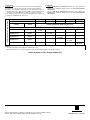
Instructions:
1. Find the column for the model of outdoor unit that is being installed.
2. Find the row for the model of the indoor unit that is being installed.
3. Find the cell in the table in which this row and column meet. In this cell
the appropriate orifice / TXV and charge addition for this match are listed.
If the text in this cell is BOLD, then a change of orifice is necessary.
4. If a change in restrictor is necessary, then the appropriate restrictor will
already be supplied with the outdoor unit.
Examples:
• FortheJS4QE-024KB/C8QAMX24U-BmatchthecorrectTXVisthe
669681 and no additional charge needs to be added (NO CHANGES
NECESSARY).
• For the JS6QF-042K / C8QAMX42U-B match the correct TXV is the
669684 and no additional charge needs to be added (NO CHANGES
NECESSARY).
ID RESTRICTOR INSTALLED WITH ID UNIT
MODEL NUMBERS: JS4QE-024KB JS4QE-030KB JS4QE-036KA JS6QF-042K JS6QF-048K
TOTAL SYSTEM CHARGE (OZ.) 64 67 58 91 94
MODELS
SUPPLIED
WITH ID
REQUIRED RESTRICTOR OR TXV
(CHARGE ADDITION (OZ) / RATED AIRFLOW - SCFM)
C8-X
C8QAMX24U-B 669564
669564
(0 / 780)
-- -- -- --
C8QAMX30U-B 669565 --
669565
(0 / 1000)
-- -- --
C8QAMX36U-B 669566 -- --
669566
(0 / 1200)
-- --
C8QAMX42U-B 669684 -- -- --
669684
(0 / 1250)
--
C8QAMX48U-B 669684 -- -- -- --
669684
(0 / 1440)
NOTES
• Thechargeslistedareonlyvalidforthestandard15’lineset.
• Numberslistedas0.***arerestrictordiameters,whilenumberslistedas669***areTXVpartnumbers.
Table 4. Restrictor or TXV / Charge Addition (Oz)
Specifications & illustrations subject to change without notice or incurring obligations (07/15).
O’Fallon,MO,©NortekGlobalHVACLLC2015.AllRightsReserved.
-
 1
1
-
 2
2


Unbranded JS6QF User guide
- Type
- User guide
- This manual is also suitable for
Ask a question and I''ll find the answer in the document
Finding information in a document is now easier with AI
Related papers
-
Broan NS4BD-KA User guide
-
Broan FS4BD-KA/B User guide
-
-
-
-
-
Unbranded PSA4BD-KA/B User guide
-
-
-