CORRECT LP GAS TANK USE
[] LP Gas grill models are designed for use with a
standard 20 lb. Liquid Propane Gas (LP Gas) tank,
not included with gdll. Never connect your gas grill to
an LP Gas tank that exceeds this capacity. A tank of
approximately 12 inches in diameter by 18-1/2 inches
high is the maximum size LP Gas tank to use. You
must use an "OPD" gas tank which offers a listed
Overfill Prevention Device. This safety feature
prevents tank from being overfilled which can cause
malfunction of LP Gas tank, regulator and/or grill.
[] The LP Gas tank must be constructed and marked in
accordance with the Specifications for LP-Gas Cylin-
ders of the U.S. Department of Transportation (D.O.T.)
or the National Standard of Canada, CAN/CSA-B339,
Cylinders, Spheres and Tubes for Transportation of
Dangerous Goods; and Commission, as applicable.
[] The LP Gas tank must have a shutoff valve, terminat-
ing in an LP Gas supply tank valve outlet, that is
compatible with a Type 1 tank connection device. The
LP Gas tank must also have a safety relief device
that has a direct connection with the vapor space of
the tank.
[] The tank supply system must be arranged for vapor
withdrawal.
[] The LP Gas tank used must have a collar
to protect the tank valve.
[] Never connect an unregulated LP gas tank to your
gas grill. The gas regulator assembly supplied with
your gas grill is adjusted to have an outlet pressure
of 11" water column (W.C.) for connection to an LP
gas tank. Only use the regulator and hose assembly
supplied with your gas grill. Replacement regulators
and hose assemblies must be those specified by
Sears. See Parts List.
[] Have your LP Gas dealer check the release valve
after every filling to ensure it remains free of defects.
[] Always keep LP Gas tank in upright position.
[] Do not subject the LP Gas tank to excessive heat.
[] Never store an LP Gas tank indoors. If you store
your gas grill in the garage always disconnect the
LP Gas tank first and store it safely outside.
[] LP Gas tanks must be stored outdoors in a well-
ventilated area and out of the reach of children.
[] Disconnected LP Gas tanks must not be stored in a
building, garage or any other enclosed area.
[] The regulator and hose assembly can be seen after
opening the doors (if applicable) and must be
inspected before each use of the grill. If there is
excessive abrasion or wear or if the hose is cut, it
must be replaced prior to using the grill again.
[] Never light your gas grill with the lid closed or
before checking to ensure the burner tubes are fully
seated over the gas valve orifices.
[] Never allow children to operate your grill. Do not
allow children or pets to play near your grill.
12
[] Use of alcohol, prescription or non-prescription
drugs can impair your ability to properly assemble
and safely operate your grill.
[] Keep fire extinguisher readily accessible. In the
event of a oil/grease fire, do not attempt to
extinguish with water. Use type B extinguisher
or smother with dirt, sand or baking soda.
[] In the event of rain, cover the grill and turn off
the burner and gas supply.
[] Use your grill on a level, stable surface in an
area clear of combustible materials.
[] Do not leave grill unattended when in use.
[] Do not move the appliance when in use.
[] Allow the grill to cool before moving or storing.
[] Do not use your grill as a heater.
[] This grill is not intended to be installed in or on
recreational vehicles and/or boats.
[] Never use charcoal in this gas grill.
A. Do not store a spare LP-Gas tank under or near
this appliance.
B. Never fill the tank beyond 80 percent full; and
C. If the information in "(a)" and "(b)" is not followed
exactly, a fire causing death or serious injury may
occur.
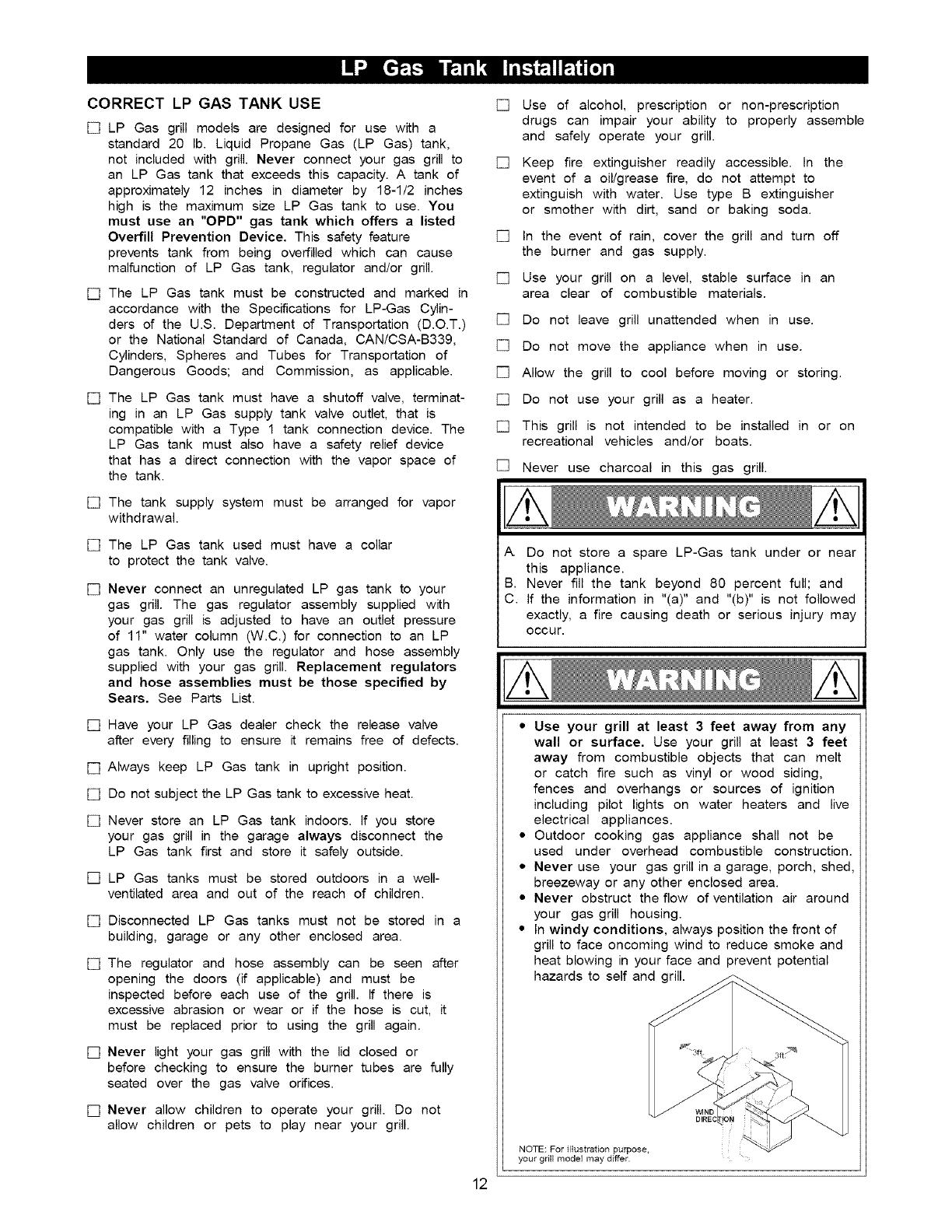
• Use your grill at least 3 feet away from any
wall or surface. Use your grill at least 3 feet
away from combustible objects that can melt
or catch fire such as vinyl or wood siding,
fences and overhangs or sources of ignition
including pilot lights on water heaters and live
electrical appliances.
• Outdoor cooking gas appliance shall not be
used under overhead combustible construction.
• Never use your gas grill in a garage, porch, shed,
breezeway or any other enclosed area.
• Never obstruct the flow of ventilation air around
your gas grill housing.
• In windy conditions, always position the front of
grill to face oncoming wind to reduce smoke and
heat blowing in your face and prevent potential
hazards to self and grill.
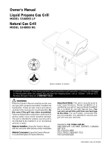
NOTE: For illustration purpose.
your grill model may differ. :