FLAME
ROLL-OUT
SUPPLY
AIR LIMIT
PRESSURE
SWITCH
PRESSURE
SWITCH
PRESSURE
SWITCH
PRESSURE
SWITCH
FLAME SENSOR
GAS
VALVE
HI
LO
C
11
4
1
8
7
10
5
2
9
3
12
6
LINE- N
XMFR-N
LINE
LINE
XMFR
EAC
HUM
LINE- N
14325
R
C
TX
RX
W
COM
IGNITOR
DOOR
SWITCH
RCY/Y2 W2GW1Y1
1
2
1
2
LOW
HIGH
BLOWER
LIMIT
BLOWER
LIMIT
CFM
MOTOR
GNDSENDHUM Y1
H
L2-OUT
L2-IN
L1-IN
L1-OUT
Y1Y/Y2W
CR
HP
SPEED
COMMON
PWM
MODE
OPEN
OPEN
FAULT
R
C
GND
RX
TX
W
C
DX-
DX+
R
RED
GREEN
24 V
120 V
WHITE
BLACK
WHITE W/ BLK STRIPES
BLK W/ WHITE STRIPES
1234
1234
INDUCER
H
L
C
123
123
BLACK
WHITE
BLACK
BLACK
1
2
3
4
5
6
1
2
3
4
5
6
COOL
FAN SPEED
HEAT
BLWR OFF
DELAY
RED
RED
RED
PA R T O F
MOTOR
123
123
BLUE
BLUE
BLUE
BLUE
BLUE
BLACK
WHITE
BLACK
BLACK
BLACK
BLACK
WHITE
BLACK
WHITE
WHITE
RED
RED
GREEN
GREEN
BROWN
BROWN
YELLOW
VIOLET
VIOLET
ORANGE
ORANGE
VENT LIMIT
(ON SELECT
MODELS)
BLACK 120V
WHITE (NEUTRAL)
GROUND
CONDENSATE
(ON SELECT
MODELS)
BLACK
VIOLET
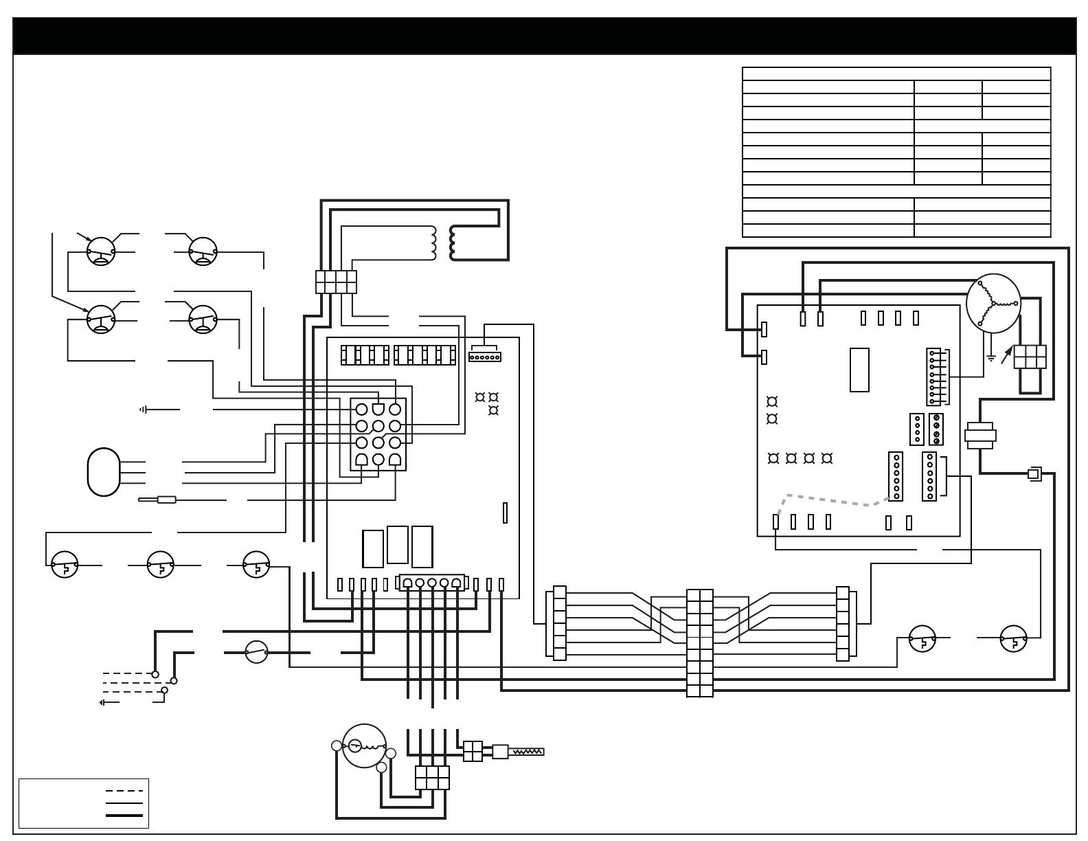
For 80+ and 90+ 2-Stage Variable Speed Upflow Furnaces
WIRING DIAGRAM
710811D
FIELD WIRING
LEGEND:
LOW VOLTAGE
HIGH VOLTAGE
Refer to the Installation Instructions
provided with the kit for the proper
heating and cooling speeds for your
application.
If any of the origInal wire as supplied with the
furnace must be replaced, it must be replaced
with wiring material having a temperature
rating of at least 105° C.
Use copper conductors only.
This wiring diagram shows connections and
termination required for the blower kit only.
Use in addition to the wiring diagram for the
furnace.
¢710811p¤
Control Fault (No Power) Off Off
L1 / Neutral Polarity Fault Flash Flash
Pressure Switch Closed Fault On Flash
Pressure Switch Open Fault Flash On
Open Limit Switch Fault Flash Off
0408
ORANGE
MOTOR CHOKE
(ON 3/4 AND 1HP
MOTORS ONLY)
BLUE BLUE
BLACK
WHITE
BLACK
WHITE
BROWN
RED
ORANGE
YELLOW
GREEN
BLUE
BROWN
RED
ORANGE
YELLOW
GREEN
BLUE
