Page is loading ...

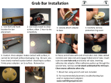
A-2000™
Unloading, Handling
and Installation Guide
ENGINEERED SOLUTIONS

2
Preface
This instruction book is for your crews. Distribute it
to help them install Contech
®
A-2000™ correctly.
They are flexible pipes that must be installed
following the trench construction, bedding,
haunching, initial backfill, and other requirements
of ASTM D 2321,“Standard Recommended
Practice for Underground Installation of Flexible
Thermoplastic Sewer Pipe.”
Don’t assume experienced workers know all
the answers. Review these instructions with your
supervisors and crews. It can mean a better job
for you and your customer.
We suggest that you adopt a policy of
performance testing the first few manhole runs.
It will give you an early check that installation
procedures are correct.
If you have any questions about these instructions,
call your Contech Distributor or your Contech
Sales Engineer, or carefully review the installation
guide in the Contech A-2000 catalogs and ASTM
D 2321.

3
Contents
Cold Weather Installation ......................... 5
Unloading and Handling .......................... 6
Trenching ................................................ 8
Installation Tips ........................................ 9
Assembly of Pipe .................................... 10
A. Gasket/Pipe Connection .............. 10
B. Manhole Connection .................... 12
C. Field Cutting Pipe ........................ 14
D. Caps ........................................... 14
E. Mechanical plugs ......................... 14
F. Tapping/Saddle Connections ......... 15
Repairs .................................................. 18
Installation of Pipe ................................. 20
A. Pipe Zone/Embedment Material .... 20
B. Deflection Control ........................ 26
Deep Laterals ........................................ 27
Special Notes ........................................ 28
Standard Details ..................................... 30
This safety alert symbol indicates
important safety messages.
When you see this symbol,
be alert to the possibility of
personal injury and be sure you
understand the message that follows.

4
Terms You Should Know
Alerts you to
hazards or unsafe
practices that CAN result in severe
personal injury or property damage.
Messages about
procedures or actions
that must be followed for safe
handling and installation of A-2000
Pipe.
Falling or rolling pipe
can cause severe
personal injury
or death.
Read and follow all safety instructions
before unloading pipe.

5
Cold Weather Installation
1. Handle the pipe with more care in cold
weather. PVC outer walls can become
hardened as temperatures drop. When placing
embedment materials in deep trenches and
temperatures 0° - 32° F, it is required to use
smaller aggregate (3/4- inch max.) and limit
the height of dumping stone, not to exceed
20 feet.
2. Rubber gaskets become harder as the
temperature decreases, gaskets tend to
compress less, and when combined with PVC
bells that become more installation sensitive,
jointing becomes less forgiving. Proper
bell-spigot alignment, adequate bell and
spigot lubrication, and recommended joining
procedures (-i.e. bar and block) all become
more essential as temperature decreases.
In addition, it is recommended to store the
gaskets in a warm place prior to use.

6
Unloading and Handling
The following equipment is recommended for
unloading pipe pallets:
Forklift with full-length forks to engage entire
pallet width, front-end loader or backhoe
with fork adapters full length to engage entire
pallet width.
Nylon lifting slings of sufficient strength and
length to safely handle entire pallet. Do
not stand or ride on the pipe load during
unloading.
NOTE: Pipes sizes 18” and less are palletized with
steel straps around a wood frame. Full trailer width
pallets (21” to 36”) are not framed. Only forks of
sufficient length to engage entire pallet width are
recommended for unloading.
Table 1. A-2000 PVC Handling Weights
Diameter (in) Weight (lbs/ft)
4 1.00
6 1.25
8 2.00
10 3.00
12 4.25
15 7.00
18 10.00
21 13.00
24 17.00
30 25.00
36 34.00

7
Failure to follow these instructions can result in
serious injury or death and/or damage to pipe.
1. Only trained and authorized equipment
operators are to be permitted to unload the
trailer.
2. Wear approved safety hat and shoes, gloves, and
eye protection.
3. Park the truck and trailer on level ground before
you start unloading.
4. Keep all unauthorized persons clear of the area
when the driver releases the binders from the
trailer and during unloading.
5. Do not release steel strapping around the wood
frame until the pallets have been placed on level
ground and will not be moved again as a unit.
6. Know the capabilities and rated load capacities
of your lifting equipment. Never exceed them.
7. Do not stand or ride on the load of pipe while it
is being unloaded. Do not stand beneath or near
the pipe when it’s being unloaded.
8. If unloading at multiple points,
secure pallets between drop
off points. For each unit of
four pallets, always unload the
top pallets first. (See diagram)
9. Never attach chains or wire
rope to the pipe. They could damage the pipe.
10. Do not push pallets off the trailer or permit pipe
to drop to the ground.
11. Do not drag A-2000 Pipe across the ground.
12. Do not stack A-2000 Pipe over two pallets high.
Stacks of three or more pallets can damage
bottom pipes and can become unstable.
13. Handle A-2000 Pipe with extra care in freezing
or cold weather.

8
Trenching
Trenching practice and bedding materials shall be
in accordance with ASTM D2321 and OSHA rules.
1. The excavation needs to be wide enough
and be supported adequately to allow a
person to work safely.
2. Where trench walls are unstable, the contractor
may elect to use sheeting, stay bracing, or
a trench box for stabilization during pipe laying. If
the conditions are severe, sheeting may be left in
place.
3. Excessive groundwater may necessitate dewatering.
4. An unstable trench bottom must be stabilized at the
engineer’s direction. In such cases, install special
foundation and bedding materials in 6-inch layers
and compact.
5. Excavation from 6 inches to 12 inches below the
pipe should be filled with acceptable bedding
material and compacted to a minimum 90%
Standard Proctor Density. Fill areas of over
excavation beyond 12 inches with processed stone
or gravel following standard bedding practices
6. Before installing the pipe, bring bedding material
to grade along the entire length of the pipe.
7. When excavating in Class IV materials (silt, silty
clays, and clays), provide a uniform, undisturbed
foundation.

9
Installation Tips
1. At manholes, flexible manhole connections like
rubber boots, A-Loks, etc. can be used.
With rubber boot manhole connectors, install
either a standard A-2000 double
gasket (8”-10”) or an A-2000 manhole gasket
(12”-36”) on the pipe spigot under the stainless
steel strap (see manhole connection detail on page
12). Where manholes are manufactured with A-Lok
connections, use a Contech PVC manhole sleeve.
2. Do not probe for the pipe with rods, shovels, or
other sharp objects when excavating down to
install laterals, etc. Instead, mark the elevation of
the pipe with stakes or other markers to help locate it.
3. When haunching the pipe or digging down to
install laterals, take care not to damage the pipe
with shovels, or other construction equipment.
4. String only enough pipe to use during the day’s
laying operations.
5. A full line of adapters to other pipes is available. See
Contech A-2000 Fittings Catalogs.
6. After proper assembly, the first load of backfill
should be placed over the middle of the pipe.
While the first load is being placed, the free bell
end should be held safely on line by the pipe layer.
This technique will minimize pipe movement during
backfilling. Subsequent loads of backfill may be
placed in a normal fashion.

10
Assembly of Pipe
A. Gasket/Pipe Connection
1.The double sealing surface A-2000 gaskets
are fitted to the first two full corrugations on the
spigot end of the pipe as shown in the drawing.
The single sealing surface A-2000 Drainage
gaskets are fitted in the first corrugation valley
as shown in the drawing.
Gaskets are shipped loose and require field
installation on the pipe spigot. The leading
(lower) edge of the gasket is marked with the
Contech logo and wording to distinguish it from
the seating (higher) edge.
The low height seal is fitted into the first
corrugation. The double sealing gasket is fitted
into the first two full corrugation valleys.
Gasket location
on 4” to 36”
diameter
A-2000
Pipe
end
Spigot
Bell
(plant-
formed)
Gasket location
on A-2000 pipe

11
2. Thoroughly clean the bell and spigot ends,
making sure they are free of mud and grit. If the
gasket has been removed, make sure the gasket
seat (the first two full corrugation valleys) is
clean. Reinstall the gasket by stretching it over
the spigot end and nesting it into the seat.
3. Use a Johnny mop or brush to apply a liberal
amount of gasket lube to the gasket and to
swab the inside of the bell. Take care to lube
the chamfered (leading) edge of the bell. Keep
lube and lubed surfaces free of debris.
4. Align the joint and push the spigot to the
corrugation with the homemark. The total
corrugation, with the homemark, should be
visible when the pipe is properly “homed.” When
using a bar and wood block, make sure the
block protects the pipe end from the bar. It is
recommended to use a nylon sling to facilitate
handling and joining 21” diameter and larger
A-2000. When joining, NEVER use the backhoe
bucket to push against the pipe bell. When
pushing the joint home, make sure the bedding
material is not pulled into the bell by the spigot.
Material such as small stones or sand pulled into
the bell as the pipe is stabbed can impair gasket
sealing and cause leaks.

12
B. Manhole Connection
At manholes, flexible manhole connections like
rubber boots, A-Loks, etc. can be used.
1. Boot: With rubber boot manhole connectors,
install either a standard A-2000 double gasket
(8”-10”) or an A-2000 manhole gasket (12’-36”)
on the pipe spigot under the stainless steal strap
(See manhole connection detail A.)
2. A-Lok: Where manholes are manufactured
with A-Lok connections, use a Contech PVC
manhole sleeve (See manhole
connection detail B.)
If the manhole sleeves are
not attached and the need
arises in the field, follow the
procedure below.
• Place a standard gasket
on the pipe about 6” from the end. Lube
the gasket and the manhole sleeve and
slide the manhole sleeve onto the pipe end.
Restrict the coupling from sliding and push
the unit (pipe and coupling) into the A-Lok
connection (lube the A-Lok).
Manhole Detail A
Manhole Detail B

13
3. Waterstop type manhole connections can be
accomplished using A-2000 pipe gaskets. For
cast-in-place concrete bottoms, precast bottoms
with “mouse hole” or similar pipe-to-manhole
entry that does not incorporate a flexible
connection, use two standard A-2000 double
gaskets for 8”-and 10”-diameter pipe, positioned
on the pipe in the center of the manhole wall
with the leading (the lower) edge of the gaskets
in adjacent corrugations, then concrete grout or
seal the pipe/manhole connections as required.
For pipe with diameters of 12”-36” inches, use
one standard A-2000 double gasket, positioned
on the pipe in the center of the manhole wall,
with the leading (lower) edge of the gasket closest
to the inside of the manhole.
Waterstop Manhole Connection

14
C. Field Cutting Pipe
A-2000 can be field cut to length. Cut through
a corrugation valley using a hand or power
saw. Fit the gasket following the procedure
listed in “Gasket/Pipe Connection.”
D. Installing Caps
Caps are installed the same way you make a
gasketed joint. Caps need to be staked to make
sure they are secure. Mark the lateral location and
depth with a lath or other marker so that probing,
etc. to locate the pipe is not required.
E. Installing Mechanical Plugs
Mechanical plugs may be used, but caps
are recommended. (Mechanical plugs
should not be used for air testing.)
Install mechanical plugs by following
these steps:
1. DO NOT USE LUBRICANT.
2. Insert into the pipe barrel, beyond the
bell, until the back of the washer seats
against the bell hub transition.
3. Hold and tighten the wing nut until
firmly seated.
4. Stake the plug to keep safely secured during
testing. Proper staking requires a spacer from
the plug in the bell to a stake driven outside
the bell.
5. Mark the lateral location and depth with
a lath or other marker so the probing
etc. to locate the pipe is not required.

15
F. Tapping/Saddle Connections
Saddle fittings are used for tapping
in-service systems. Use inline fittings
for new construction. Ribbed A-2000
saddles must line up with pipe corrugations.
Stick-on templates are marked for proper
orientation.
Follow these steps:
1. Place template on the pipe to mark the
outline of the hole. Take care to line up the
template with the corrugation valley properly.
Instructions are located on the template.
2. Use keyhole or saber saw to cut the
hole. Do not start the hole with a
hammer or hatchet. Use a drill, awl, or
other sharp cutting tool.
3. Thoroughly clean the pipe and saddle
mating areas (e.g. MEK cleaner or other).
Place the saddle in position on the pipe
and draw a line around the outer
edge of the saddle skirt to mark the
area of pipe to be covered by the
saddle. Use the recommended adhesive
(Sikaflex
®
or similar) provided by others.
Adhesive is in the caulking tube that uses a
standard caulking gun. Proceed as
described on the following page.

16
3.A. For saddles with ribbed skirt.
3.A.1. Place a 1/4 -inch bead around the
cut opening in the pipe. Continue to make
concentric rings with 1/4 -inch beads of
adhesive about 1/4 -inch apart. The final
ring should be just inside the area to be
covered by the saddle skirt. Make certain
when crossing corrugation valleys that the
adhesive bead flows into the valley.
3.A.2. Apply adhesive to the underside of
the saddle skirt in a similar fashion.
3.B. For saddle with smooth (underside) skirt.
3.B.1. Completely fill the corrugation
valleys of the pipe with adhesive. The
bead should completely fill the valleys
and bulge above the corrugation crests
throughout the area to be covered by the
saddle.
3.B.2. Place a 1/4 -inch bead around the
cut opening in the pipe. Continue to make
concentric rings with 1/4 -inch apart. The
final ring should be just inside the area to
be covered by the saddle skirt.

17
3.B.3 Apply adhesive to the underside of the
saddle skirt in a similar fashion.
With either type of skirt, a bead of adhesive can
be applied to the cut edge of the pipe wall to seal
the profile if desired.
NOTE: 8-inch to 36-inch saddle gaskets are also
available to be used with smooth skirt saddles.
Step 3.B.1. is not required for saddles with
gaskets. In steps 3.B.2. and 3.B.3., adhesive may
be applied to either the saddle or gasket surface.
4. Place saddle in position on the pipe
and cinch in place with the two steel
straps provided. Tighten straps
uniformly by alternating back and forth
between them, tapping the saddle
lightly with a rubber mallet to aide in
firmly seating the saddle in position (do
not over-tighten the straps).
5. For attaching 21-inch to 36-inch (only)
A-2000 saddle fittings with
the smooth saddle skirt, follow the
procedure described in Steps 1, 2, 3,
and 3B above. In addition, place
saddle in position on the pipe and
fasten in place with the stainless steel
screws provided. Holes are predrilled in
saddles for location of screws.

18
Repairs
Cut out damaged areas and cut a length of
replacement pipe to fit. Use two flexible rubber
couplings and follow these steps:
1. Expose the existing cut pipe ends to give working
room under them.
2. Install a flexible rubber adapter on each end of
the replacement section. Using gasket lube or
vegetable oil as a lubricant, slide (or roll) the
adapters back and position the replacement
section.
3. Slide (or roll) the adapters over the joint at each
end of the replacement section so they
are centered over the joint. Use gasket lube or
vegetable oil as a lubricant.
4. Tighten the two stainless steel bands, making
certain they are properly positioned.
5. When optional shear stops are required, the
split plastic ring is snapped around the repair
coupling between the stainless steel bands
(Steps 3 and 4). This ring is held in place by two
additional stainless steel straps. The shear stop is
installed prior to re-establishing bedding support.
6. Tamp bedding material under the points where
it was disturbed. Replace haunching and initial
backfill throughout the disturbed area.
Alternate Repair Procedure

19
Place gaskets on each spigot end of the
embedment pipe backwards (with the higher or
seating edge of the gasket adjacent to the pipe
cut.) Place gaskets on each end of the replacement
piece in the recommended fashions. Draw
homemarks a half coupling length from end
of each spigot end on the replacement length.
Liberally lube all gaskets and inside of couplings.
Cut out damaged areas.
Align replacement length with existing spigots and push repair couplings to
homemarks.
Place couplings over each spigot end of embedded pipe.

20
Installation of Pipe
A. Pipe Zone/Embedment Material
Embedment Materials
Embedment materials are those used for bedding,
haunching, and initial backfill. All materials should
be installed and compacted in 6-inch maximum lifts.
ASTM D2321 classifies soil materials as:
Class IA Manufactured aggregates: Open graded
clean, angular, crushed stone or rock, crushed gravel,
broken coral, crushed slag, cinders or shells, large void
content, with little or no fines. These materials compact
with little or no mechanical effort.
Class IB Manufactured, processed aggregates: Dense,
graded clean, angular, crushed stone (or other Class
IA materials) and stone/sand mixtures with gradations
selected to minimize migration of adjacent soils,
containing little or no fines. Compact to 85% Standard
Proctor Density with hand tampers or vibratory
compaction.
/