Page is loading ...

Öhlins Radial Caliper Bracket Kit is designed for
Brembo radial calipers. The Kit contains left and right
caliper brackets and fork bottom pieces. Spacers
for larger diameter brake disks are provided
Kit 4791-01 includes caliper brackets with 100
mm c-c screw holes.
Kit 4791-02 includes caliper brackets with 108
mm c-c screw holes.
No wheel spacers or fender brackets are included
in this kit.
The brackets have a side offset of 13.3 mm. The
brake discs must have an offset corresponding
to this measure.
CAUTION!
It is of vital importance that brake discs with correct
offset are used
Bracket without spacers fits brake discs with a
diameter of 290 mm.
When spacers are used discs with a diameter of
320 mm can be fitted.
WARNING!
When radial brake calipers are mounted to earlier
Front Forks 43 the fork bottoms must be changed.
New fork bottoms are provided with the kit. Chang-
ing fork bottoms demands good mechanical skills
and special tools. This kit must be changed by an
authorized Öhlins Service Centre
Mounting Instructions
Öhlins Radial Caliper Bracket Kit
04791-01 and 04791-02
© Öhlins Racing AB. All rights reserved. Any reprinting or unauthorized use without the
written permission of Öhlins Racing AB is prohibited. Printed in Sweden.
NOTE!
Before dismantling the front fork check the
settings and make a note on rebound and com-
pression clicks and spring pre-load setting.
Öhlins Racing AB, Box 722, S-194 27 Upplands Väsby, Sweden.
Phone +46 8 590 025 00. Fax +46 8 590 025 80.
www.ohlins.com
Part No. 04791-01. Issued 03 05 12
Checking sag and ride height
Front suspension
F1. Bike on a stand with the
suspension fully extended = ............
F2. Bike on the ground without rider = ............
F3. Bike on the ground with rider = ............
Free sag
F1 - F2 = ............
Ride height
F1 - F3 = ............
Bike on a stand.
F1
R1
Bike on the ground.
F2
R2
Bike with rider on.
F3
R3
Rear suspension
R1.Bike on a stand with the
suspension fully extended = ............
R2.Bike on the ground without rider = ........... .
R3.Bike on the ground with rider = ............
Free sag
R1 - R2 = ............
Ride height
R1 - R3 = ............
Safety signals
Important information concerning safety is
distinguished in this manual by the
following notations:
The Safety alert symbol means:
Caution! Your safety is involved.
WARNING!
Failure to follow warning instructions
could result in severe or fatal injury
to anyone working with, inspecting or
using the suspension, or to bystanders.
CAUTION!
Caution indicates that special pre-
cautions must be taken to avoid dam-
age to the suspension.
NOTE!
This indicates information that is of
importance with regard to procedures.
Before installation
Öhlins Racing AB can not be held responsible for
any damage whatsoever to suspension or vehicle,
or injury to persons, if the instructions for fitting
and maintenance are not followed exactly.
Similarly, the warranty will become null and void
if the instructions are not adhered to.
WARNING!
Installing a suspension, that is not approved
by the vehicle manufacturer, may affect the
stability of your vehicle. Öhlins Racing AB
cannot be held responsible for any personal
injury or damage whatsoever that may occur
after fitting the suspension. Contact an
Öhlins dealer or other qualified person for
advice.
Öhlins products are subject to continual improve-
ment and development. Consequently, although
these instructions include the most up-to-date
information available at the time of printing, there
may be minor differences between your front fork
and this mounting instruction. Please consult your
Öhlins dealer if you have any questions with re-
gard to the contents of the mounting instruction.
Kit contents
Before installing the Caliper Bracket Kit, please
check the contents of the kit. If anything is
missing, contact your Öhlins dealer.
Description Pcs. Part No.
04791-01
Caliper bracket LH 1 01593-13
Caliper bracket RH 1 01593-14
04791-02
Caliper bracket LH 1 01593-11
Caliper bracket RH 1 01593-12
Caliper spacer 4 01669-03
Caliper sleeve 4 01669-02
Fork bottom assy 2 04742-05
O-ring 2 04722-08
Sticker Öhlins 2 00194-10
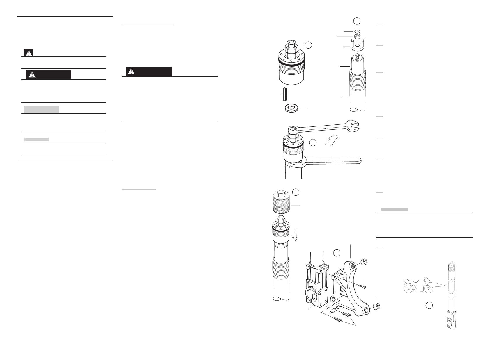
21
Reinstall the pre load tube, the upper spring seat
and the nut of the piston rod..
22
Apply red grease (146-01) to the washer and the
key and fit them to the top nut assy. (Top nut A/B
assy only)
23
Pull the piston rod upwards and screw it into the
top nut assy. Use Top nut holder (4705-01) or a
17 mm wrench to keep a firm hold of the cartridge
nut, use a 12 mm wrench on top nut assy “A/B”
and a 17 mm wrench on top nut assy “C/D” and
tighten to a torque of 30 Nm.
24
Pull the outer tube up and reinstall the top nut. Use
top nut tool (797-04) and tighten it gently by hand.
25
Fit the radial caliper brackets.
Torque: M8=25Nm, M6=12 Nm.
26
Adjust compression and rebound by first turning
the adjusters clock vise to 0-position. Then turn
them counter clock vise to correct number of
clicks according to your notes. Set the pre-load.
27
Reinstall the fork legs to the motorcycle.
NOTE!
The shaft hole of the fork bottom has a diameter of
32 +0,05 -0 mm. We recommend a sleeve with the
following valves: 32 h9 +0 -0,052. Max. radial play
between the sleeves and the wheel shaft is 0,1 mm.
21
22
23
24
27
25
Washer
Nut
Spring
seat
Pre-load
tube
Outer
tube
Key
Washer
12 mm wrench
17 mm wrench
Top nut assy tool 797-04
Front fork
bottom
Spacer
Caliper bracket
30 Nm
M6 screw
M8 screws
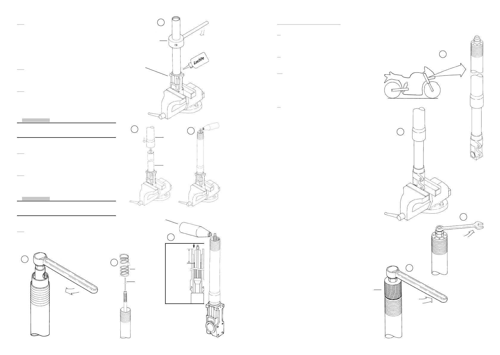
28
The sleeve 01669-02 shall be mounted with the
chamfer inside the caliper bracket, not inside the
brake caliper.
4
Mounting instructions
1
Remove the front fork legs from the motorcycle.
2
Fasten the fork leg in a vice. Use soft jaws.
3.
Loosen the spring pre load by turning the upper
adjustment nut counter clock vise. Use a 12 mm
wrench to Top nut type “A/B” and a 17 mm
wrench to Top Nut type “C/D”
4
Loosen the top nut assembly. Use Top nut tool
(797-04).
1
2
3
Top nut tool 797-04
15
Make sure that the thread of the inner tube is clean
and free form oil, grease and loctite. Position the
o-ring (04722-08) provided into the bottom piece.
When reinstalling the inner tube to the new fork
bottom piece, locking fluid Loctite 270 or similar
must be used. Tighten to a torque of 110 Nm.
16
Install the outer tube. Fill 500 ml Öhlins front fork
oil (1309-01).
17
Insert the piston rod assy into the cylinder. Apply
some red grease (146-01) to the tread and tighten
to a torque of 40 Nm. Use a torque wrench
NOTE!
Open the compression adjuster fully before
pumping procedure. Use a 3 mm allen tool
18
Push the piston rod up and down until the
cartridge is completely filled with oil.
19
Reinstall the adjustment rod and put the spring
back into the fork leg.
NOTE!
The spring is to be positioned with the marking
number upwards.
20
Measure the oil level and adjust to correct level
(see spec. card for correct data)
17
15
16
16
20
Oil level
See
spec. card for
correct fluid level
Tool 786-05
New bottom piece
Loctite 270
Outer
tube
Inner
tube
Spring
Öhlins front fork oil
1309-01
19
Adjustment
rod
110 Nm

5
Let the outer tube drop down. Use Top nut holder
(4705-01) or a 17 mm wrench to keep a firm hold
of the piston rod nut.
CAUTION!
Beware not to damage the O-ring.
NOTE!
When a standard 17 mm wrench is used, the
upper spring seat must be pressed down, to make
access to the nut.
6
Remove the top nut assy from the piston rod.
Use a 12 mm wrench. On top nut type “A/B” the
washer and the key should be removed.
7
Unscrew and remove the upper nut from the
piston rod to release the upper spring seat and
the pre-load tube.
8
Use a steel wire shaped to a hook in one end to
grip the spring and pull the spring out.
9
Free the front fork from the vice and pour the
front fork fluid out.
NOTE!
The adjustment rod must be held in position not
to fall out.
10
Put the front fork leg back into the vice and care-
fully slide the outer tube upwards to remove it.
NOTE!
Use a cloth to avoid excess oil to trickle out from
the tube
5
7
8
9
Top nut assy
Spring seat
Pre-load tube
Inner tube
Outer tube
Spring
6
12 mm wrench
17 mm wrench
Outer tube
11
Loosen the piston rod assy and pull it out. Use
Cartridge tool (4702-01).
12
Free the fork bottom and inner tube from the vice
and pour the remaining oil out.
13
Fasten the fork bottom to the vice again.
14
Remove the inner tube from the fork bottom. Use
of clamp tool (786-05) and a heat air gun to
release the fork bottom from locking fluid.
12
11
14
Cartridge tool
4702-01
Piston rod
assy
Inner tube
Fork bottom
Heat air gun
Clamp tool
786-05
15
Make sure that the serial number on the old fork
bottom will be printed/punched on the new
NOTE!
This must be done to be able to identify the front
fork in the future!
fork bottom.
/