
02.20· 174.02.079/3
Subject to modification in technic and design.
www.baumer.com Errors and omissions excepted.
Manual
Absolute encoders EAx with EtherCAT interface
Firmware Version V1.0.0 and later

Baumer_EAx_EtherCAT_EN_MNL www.baumer.com
02.20 2/121
Contents Page
1. Introduction 6
1.1. Scope of delivery 6
1.2. Product classification 6
2. Safety and operating instructions 7
3. Commissioning 8
3.1. Mechanical mounting 8
3.2. Electrical connection 8
3.2.1. Cabling 8
3.2.2. Connecting 9
3.2.3. Push button for preset 11
4. Engineering (Beckhoff TwinCAT 2) 12
4.1. Start TwinCAT 12
4.2. Create project 12
4.3. Scan EtherCAT network 13
4.4. Import ESI file 15
4.5. Config Mode 18
4.6. Run Mode (real-time) 20
4.7. Process image of encoder 24
4.7.1. Default settings 24
4.7.2. Change content of process image 24
4.8. Read/Write CoE objects 26
5. Engineering (Beckhoff TwinCAT 3) 27
5.1. Start TwinCAT 27
5.2. Create project 27
5.3. Scan EtherCAT network 28
5.4. Import ESI file 30
5.5. Config Mode 31
5.6. Run Mode (real-time) 33
5.7. Process image of encoder 37
5.7.1. Default settings 37
5.7.2. Change content of process image 37
5.8. Read/Write CoE objects 38
6. EtherCAT cyclic operation 39
6.1. PLC (EtherCAT Master) 39
6.2. Basics 39
6.3. Diagnostic LEDs 40
6.3.1. Link/Activity (L/A) LEDs 40
6.3.2. EtherCAT RUN LED 40
6.3.3. EtherCAT ERR LED 41
6.4. Mapping of Process Data Objects (PDOs) 42
6.5. Speed 44
6.5.1. Speed measuring unit 44
6.5.2. Speed update period 44
6.5.3. Speed filter depth 44
6.6. Preset function 45
6.6.1. Preset via CoE object 0x6003 45
6.6.2. Preset using the push button 45
6.7. Operation modes 46
6.7.1. Overview 46
6.7.2. Free Run 47
6.7.3. Synchronous with SM3 event 48
6.7.4. DC Mode (Synchronous with Sync0 Event) 49
6.8. Cycle time and supported functionality 50
7. EtherCAT acyclic operation 51

Baumer_EAx_EtherCAT_EN_MNL www.baumer.com
02.20 3/121
7.1. CANopen over EtherCAT (CoE) 51
7.2. CiA 406 (encoder profile) 51
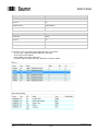
7.3. Standard CoE objects (index range 0x1000 to 0x1FFF) 52
7.3.1. Overview 52
7.3.2. Index 0x1000 (Device Type) 54
7.3.3. Index 0x1001 (Error Register) 54
7.3.4. Index 0x1008 (Device Name) 55
7.3.5. Index 0x1009 (Manufacturer Hardware Version) 55
7.3.6. Index 0x100A (Manufacturer Software version) 55
7.3.7. Index 0x1010 (Save Parameters) 56
7.3.8. Index 0x1011 (Restore Parameters) 58
7.3.9. Index 0x1018 (Identity Object) 60
7.3.10. Index 0x1A00 (TPDO 1 mapping) 62
7.3.11. Index 0x1A01 (TPDO 2 mapping) 64
7.3.12. Index 0x1A02 (TPDO 3 mapping) 66
7.3.13. Index 0x1A03 (TPDO 4 mapping) 68
7.3.14. Index 0x1A04 (TPDO 5 mapping) 70
7.3.15. Index 0x1A05 (TPDO 6 mapping) 73
7.3.16. Index 0x1A06 (TPDO 7 mapping) 75
7.3.17. Index 0x1C00 (Sync Manager Communication Types) 77
7.3.18. Index 0x1C12 (Sync Manager 2 PDO Assignment) 79
7.3.19. Index 0x1C13 (Sync Manager 3 PDO Assignment) 80
7.3.20. lndex 0x1C33 (Input Sync Manager Parameter) 81
7.4. Vendor-specific CoE objects (index range 0x2000 to 0x5FFF) 84
7.4.1. Overview 84
7.4.2. Index 0x2000 (System Time) 85
7.4.3. Index 0x2001 (Gear Factor Configuration) 86
7.4.4. Index 0x2002 (Speed Calculation Configuration) 88
7.4.5. Index 0x2003 (Position value 2 bytes) 90
7.4.6. Index 0x2004 (Speed value 4 bytes) 91
7.4.7. Index 0x2005 (Button Preset Value) 92
7.4.8. Index 0x2120 (Sensor Temperature) 93
7.4.9. Index 0x2122 (Order ID) 93
7.4.10. Index 0x2201 (Expected Cycle Time For Position Update) 94
7.5. Profile-specific CoE objects (index range 0x6000 to 0xFFFF) 95
7.5.1. Overview 95
7.5.2. Index 0x6000 (Operating parameters) 96
7.5.3. Index 0x6001 (Measuring units per revolution) 98
7.5.4. Index 0x6002 (Total measuring range in measuring units) 99
7.5.5. Index 0x6003 (Preset value) 100
7.5.6. Index 0x6004 (Position value) 101
7.5.7. Index 0x600C (Position raw value) 101
7.5.8. Index 0x6500 (Operating status) 102
7.5.9. Index 0x6501 (Singleturn resolution) 103
7.5.10. Index 0x6502 (Number of distinguishable revolutions) 104
7.5.11. Index 0x6503 (Alarms) 105
7.5.12. Index 0x6504 (Supported alarms) 106
7.5.13. Index 0x6505 (Warnings) 107
7.5.14. Index 0x6506 (Supported warnings) 108
7.5.15. Index 0x6507 (Profile and software version) 109
7.5.16. Index 0x6508 (Operating time) 110
7.5.17. Index 0x6509 (Offset value) 111
7.5.18. Index 0x650A (Module identification) 112
7.5.19. Index 0x650B (Serial number) 113
7.6. Parameterization 114
7.6.1. Measuring units per revolution 114
7.6.2. Total measuring range 114
7.6.3. Code sequence 114
7.6.4. Scaling functionality 114

Baumer_EAx_EtherCAT_EN_MNL www.baumer.com
02.20 4/121
7.6.5. Speed measuring unit 114
7.6.6. Speed update period 114
7.6.7. Speed filter depth 114
7.6.8. Gear factor: activation 115
7.6.9. Gear factor: numerator 116
7.6.10. Gear factor: denominator 116
7.6.11. Gear factor: parametrization 116
7.6.12. Important note for multiturn encoder operation 117
7.6.13. Preset 117
7.6.14. Parametrization sequence 117
7.7. Error Handling 118
7.7.1. CoE Emergency messages 118
7.7.2. Mapping table 119
7.7.3. SDO abort codes 120
7.7.4. Speed violation check 120
7.8. FoE 120
8. Troubleshooting – Frequently Asked Questions – FAQ 121
8.1. FAQ: Project Work 121
8.1.1. Where do I get an encoder manual? 121
8.1.2. Where do I get the applicable ESI file? 121
8.2. FAQ: Operation 121
8.2.1. What is the significance of the LEDs provided at the encoder? 121
8.2.2. How to adapt the resolution? 121

Baumer_EAx_EtherCAT_EN_MNL www.baumer.com
02.20 5/121
Disclaimer of liability
The present manual was compiled with utmost care, errors and omissions reserved. For this reason
Baumer rejects any liability for the information compiled in the present manual.
Baumer nor the author will accept any liability for direct or indirect damages resulting from the use of the
present information.
At any time we should be pleased receiving your comments and proposals for further improvement of the
present manual.
Created by:
Baumer IVO GmbH & Co. KG
Villingen-Schwenningen, Germany
Registered trademarks
EtherCAT
®
is a registered trademark and patented technology, licensed by Beckhoff Automation GmbH,
Germany.
TwinCAT
®
, Microsoft
®
and Visual Studio
®
are registered trademarks.
Names mentioned in the present manual and other names that may be registered trademarks are not
marked correspondingly. Having omitted the respective marking does not necessarily imply that the names
are not registered trademarks or that there are no existing patents and protected patented designs.
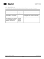
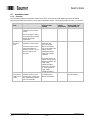
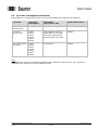
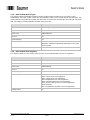
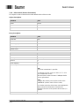
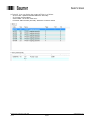
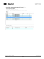
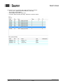
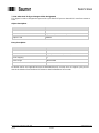
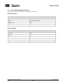
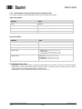
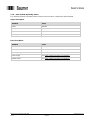
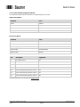
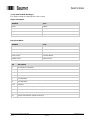
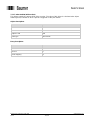
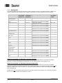
Change history
This document is subject to changes. The latest version is available at www.baumer.com.
Document
index
Date
Firmware
revision
Author
Changes
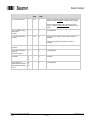
0001
09.18
1.0.1
div.
Initial version
(replaces all draft documents)
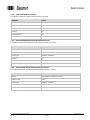
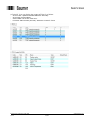
0002
02.20
1.0.2
div.
Important changes:
editorial changes and
revision of following chapters:
- 6.5 ("Speed")
- 6.7.4 ("DC Mode (Synchronous with Sync0
Event)")
- 6.8 ("Cycle time and supported functionality")
- 7.3.7 ("Index 0x1010 (Save Parameters)")
- 7.3.8 ("Index 0x1011 (Restore Parameters)")
- 7.4.3 ("Index 0x2001 (Gear Factor
Configuration)")
- 7.5.12 ("Index 0x6504 (Supported alarms)")
- 7.5.14 ("Index 0x6506 (Supported
warnings)")
- 7.6.8 to 7.6.11 (gear factor)
- 7.6.12 ("Important note for multiturn encoder
operation")
- 7.6.14 ("Parametrization sequence")
- 7.7.2 (“Mapping table")

Baumer_EAx_EtherCAT_EN_MNL www.baumer.com
02.20 6/121
1. Introduction
1.1. Scope of delivery
Please check the delivery upon completeness prior to commissioning.
Depending on encoder configuration and part number the delivery may include:
EtherCAT encoder
ESI file and manual (available at www.baumer.com)
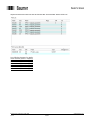
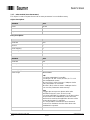
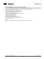
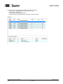
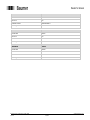
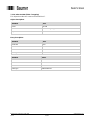
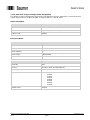
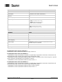
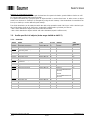
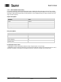
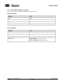
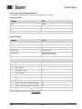
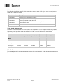
1.2. Product classification
Product
Product family
Suitable input in catalog
EAL580-xxx.xxEC.13160.x
optical - multiturn
EAL580 MT encoder ST13 MT16, optical
EAL580-xxx.xxEC.18130.x
optical - multiturn
EAL580 MT encoder ST18 MT13, optical
EAM580-xxx.xxEC.14160.x
magnetic - multiturn
EAM580 MT encoder ST14 MT16, magnetic
Explanation
- Placeholders marked “x” in the product reference number will not influence the selection
- “MT” means “multiturn”
- “ST” means “singleturn”
- “ST13 MT16” means “13 bits physical singleturn resolution, 16 bits physical multiturn resolution”
ESI file
The ESI file is the same for all products mentioned above. For details see chapters Import ESI file (for
TwinCAT 2) and Import ESI file (for TwinCAT 3).
Supported standards and protocols
CANopen CiA 406 version 4.0.2, 18.08.2016
EtherCAT specification ETG.1000 V1.03
Encoder passed ETG certification with Conformance Test Tool version 2.1.0.0.

Baumer_EAx_EtherCAT_EN_MNL www.baumer.com
02.20 7/121
2. Safety and operating instructions
Intended use
The encoder is a precision measuring device that is used to record positions and speeds. It provides
measuring values as electronic output signals for the subsequently connected device. It must not be used
for any other purpose. Unless this product is specially labeled, it may not be used for operation in
potentially explosive environments.
Make sure by appropriate safety measures, that in case of error or failure of the encoder, no danger to
persons or damage to the system or operating facilities occurs.
Personnel qualification
Installation and assembly of this product may be performed only by a person qualified in electronics and
precision mechanics.
Maintenance
The encoder is maintenance-free and must not be opened up nor mechanically or electronically modified.
Opening up the encoder can lead to injury.
Disposal
The encoder contains electronic components. At its disposal, local environmental guidelines must be
followed.
Mounting
Solid shaft: Do not connect encoder shaft and drive shaft rigidly. Connect drive and encoder shaft with a
suitable coupling.
Hollow shaft: Open clamping ring completely before mounting the encoder. Foreign objects must be kept
at a sufficient distance from the stator coupling. The stator coupling is not allowed to have any contact to
the encoder or the machine except at the mounting points.
Electrical commissioning
Do not proceed any electrical modifications at the encoder.
Do not proceed any wiring work while encoder is live.
Do not remove or plug on connector whilst under power supply.
Ensure that the entire system is installed in line with EMC/EMI requirements. Operating environment and
wiring have an impact on the electromagnetic compatibility of the encoder. Install encoder and supply
cables separately or far away from sources with high emitted interference (frequency converters,
contactors, etc.).
When working with consumers with high emitted interference provide separate encoder supply voltage.
Completely shield encoder housing and connecting cables.
Connect encoder to protective earth (PE) using shielded cables. The braided shield must be connected to
the cable gland or connector. Ideally, aim at dual connection to protective earth (PE), i.e. housing by
mechanical assembly and cable shield by the downstream devices.
Supplementary information
The present manual is intended as a supplement to already existing documentation (e.g. catalogues, data
sheets or mounting instructions).

Baumer_EAx_EtherCAT_EN_MNL www.baumer.com
02.20 8/121
3. Commissioning
3.1. Mechanical mounting
Shaft encoders
Mount the encoder using the mounting holes in the encoder flange and fitting screws. Observe thread
diameter and depth.
There is an alternative mounting option in any angular position by eccentric fixings available as an
accessory.
Connect drive shaft and encoder shaft by using an appropriate coupling. The shaft ends must not touch
each other. The coupling must compensate temperature and mechanical tolerances. Observe the
maximum permitted axial or radial shaft load. For appropriate couplings please refer to accessories.
Tighten the mounting screws firmly.
Hollow shaft encoders
Mounting by clamping ring
Prior to mounting the encoder open the clamping ring completely. Push encoder onto the drive shaft and
tighten the clamping ring firmly.
Adjusting element with rubber buffer
Push the encoder onto the drive shaft and insert the cylindrical pin into the adjusting element (customer-
mounted) and the rubber buffer.
Spring washer
Fasten the spring washer at the mounting holes of the encoder housing using screws. Push the encoder
onto the drive shaft and mount the spring washer to the contact surface.
3.2. Electrical connection
3.2.1. Cabling
EtherCAT utilizes Fast Ethernet cables (100 Mbit/s, Cat. 5).

Baumer_EAx_EtherCAT_EN_MNL www.baumer.com
02.20 9/121
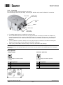
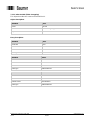
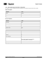
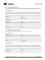
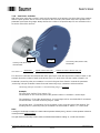
3.2.2. Connecting
The encoder provides three M12 flange connectors.
Two M12 flange connectors (D-coding, according IEC 61076-2-101) serve for EtherCAT connection.
For voltage supply use an A-coded M12 connector only.
The D-coded M12 connector “ECAT IN” may only be used to connect the encoder to the EtherCAT
network segment which is next to the EtherCAT Master. For example, if there are no other EtherCAT
Slaves between EtherCAT Master and encoder the EtherCAT Master shall be directly connected to
“ECAT IN”.
The D-coded M12 connector “ECAT OUT” may only be used to connect the encoder to subsequent
EtherCAT Slaves which are more distant to the EtherCAT Master.
Seal up any unused M12 connector using a screw cap (included in the delivery).
There are no user serviceable parts inside the encoder. There is no need for setting a node ID or a
terminating resistor. All settings required for encoder access are made in the engineering tool (for example
TwinCAT).
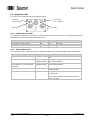
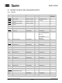
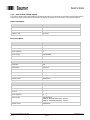
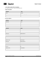
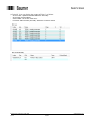
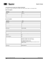
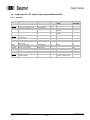
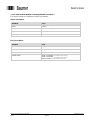
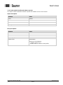
Pin assignment
Voltage supply
EtherCAT (data line)
1 x M12 flange connector (male)
2 x M12 flange connector (female)
A-coded
D-coded
Pin
Assignment
Pin
Assignment
1
UB / +Vs (10...30 VDC)
1
TxD+
2
Do not connect
2
RxD+
3
GND / 0V
3
TxD-
4
Do not connect
4
RxD-
ECAT IN
port
ECAT OUT
port
power
ERR LED
ECAT OUT
Link/Activity
ECAT IN
Link/Activity
RUN LED

Baumer_EAx_EtherCAT_EN_MNL www.baumer.com
02.20 10/121
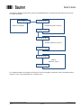
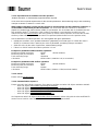
The following drawing shows how to connect “EAx580 EtherCAT” encoders and other EtherCAT Slaves to
an EtherCAT Master.
The suitable hardware for an EtherCAT Master can be for example a standard PC with a standard network
interface card or a programmable logic controller (PLC).
EAx580 EtherCAT (Slave 1)
EtherCAT Master
M12 (ECAT IN)
M12 (ECAT OUT)
EAx580 EtherCAT (Slave 2)
M12 (ECAT IN)
M12 (ECAT OUT)
weiterer
EtherCAT Slave
RJ45 (ECAT IN)
RJ45 (ECAT OUT)
RJ45

Baumer_EAx_EtherCAT_EN_MNL www.baumer.com
02.20 11/121
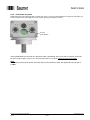
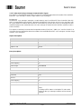
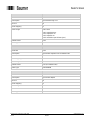
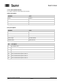
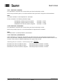
3.2.3. Push button for preset
Depending on the encoder type the encoder may have a screw cap located where connectors and LEDs are
located as well. After removing the screw cap the preset push button is visible.
If the EAx580 EtherCAT encoder is in EtherCAT state “Operational” and connected to an EtherCAT Master
the push button triggers a preset. For functionality details see chapter Preset using the push button.
Note:
After having used the push button the screw cap must be screwed in again and tightened with a torque of
1.5 Nm.
Preset
push button

Baumer_EAx_EtherCAT_EN_MNL www.baumer.com
02.20 12/121
4. Engineering (Beckhoff TwinCAT 2)
The following examples relate to Beckhoff PLCs using the engineering tool TwinCAT 2. To get information
how to configure the EAx580 EtherCAT encoder with TwinCAT 3 see chapter Engineering (Beckhoff
TwinCAT 3).
Of course the encoder will also accept engineering software of other manufacturers. In this case please
proceed in an analog way.
4.1. Start TwinCAT
Start TwinCAT for example from the Windows start menu.
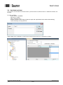
4.2. Create project
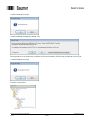
Select “New” in menu “File”.
Set TwinCAT to “Config Mode”.

Baumer_EAx_EtherCAT_EN_MNL www.baumer.com
02.20 13/121
Confirm following message.
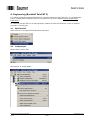
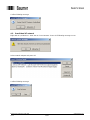
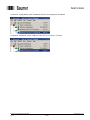
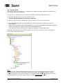
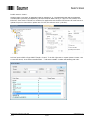
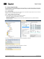
4.3. Scan EtherCAT network
Right-click on „I/O Devices”. Then click on ”Scan Devices“. Press OK if following message occurs.
Select network adapter and press OK.
Confirm following message.

Baumer_EAx_EtherCAT_EN_MNL www.baumer.com
02.20 14/121
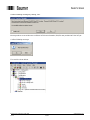
Confirm following message by clicking „Yes“.
Message above occurred because no EtherCAT Slave Information (ESI) file was provided to TwinCAT yet.
Confirm following message.
The result is shown below.

Baumer_EAx_EtherCAT_EN_MNL www.baumer.com
02.20 15/121
4.4. Import ESI file
An EtherCAT Slave is described by a so-called “EtherCAT Slave Information” (ESI) file. The file format is
XML (“Extensible Markup Language”).
The ESI file for an EAx580 EtherCAT encoder is available for download at www.baumer.com.
For encoders with firmware V1.0.0 or later use this ESI file:
Baumer_EAx580_EtherCAT_Encoders_ESI_V102.xml
The version in the filename indicates the ESI file version and may change without notice.
To provide the EtherCAT Slave Information (ESI) file to TwinCAT the following steps have to be done:
- Close TwinCAT.
- Delete ESI file “OnlineDescriptionCache000000EC.xml” which was generated automatically by TwinCAT
before in ESI folder (for example C:\TwinCAT\Io\EtherCAT).
- Copy ESI file of encoder to ESI folder (for example C:\TwinCAT\Io\EtherCAT).
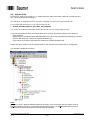
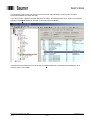
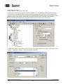
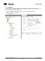
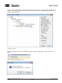
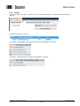
Repeat the steps mentioned in the chapters before. Now TwinCAT uses the ESI file for configuration.
The encoder is displayed as follows:
Note:
The icon for “Box 1 (Baumer EAx580 EtherCAT Encoder)” in the screenshot above is shown when an
EAL580 EtherCAT encoder is connected to the EtherCAT master. If an EAM580 EtherCAT encoder is
connected to the EtherCAT master the following will be displayed.

Baumer_EAx_EtherCAT_EN_MNL www.baumer.com
02.20 16/121
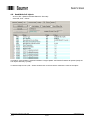
Please note that EAL580 and EAM580 EtherCAT encoders have different icons and different EtherCAT
product codes.
- EAL580 EtherCAT encoders have EtherCAT product code 0x200 (decimal: 512).
- EAM580 EtherCAT encoders have EtherCAT product code 0x300 (decimal: 768).
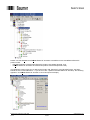
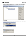
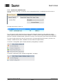
The EtherCAT product code 512 or 768 can be found in tab “EtherCAT” of an EtherCAT slave. You find it
behind the text “Product/Revision:”. If you click on “Box 1 (Baumer EAx580 EtherCAT Encoder)” the following
appears if an EAM580 EtherCAT encoder is connected (as an example).

Baumer_EAx_EtherCAT_EN_MNL www.baumer.com
02.20 17/121
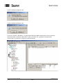
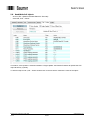
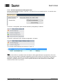
The EtherCAT product code can also be found in the CoE object dictionary of the encoder in object
0x1018:02 (subindex 2 of index 0x1018).
If you click on “Box 1 (Baumer EAx580 EtherCAT Encoder)” and select the tab “CoE - Online” the following
appears if an EAM580 EtherCAT encoder is connected (as an example).
In general the screenshots in this manual refer to EAL580 EtherCAT encoders but the handling for other
encoder types is very similar.

Baumer_EAx_EtherCAT_EN_MNL www.baumer.com
02.20 18/121
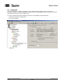
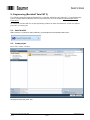
4.5. Config Mode
TwinCAT provides a so-called “Config Mode”. In this mode real-time handling of the encoder data in
TwinCAT is usually not possible. By default TwinCAT uses the “Config Mode” and the “Free Run” cycle time
of the EtherCAT Master is set to 4 milliseconds.
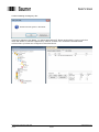
To check or change the EtherCAT Master cycle time in “Config Mode” proceed as follows:
- double-click on “Device 4 (EtherCAT)”
- click on tab “Adapter”

Baumer_EAx_EtherCAT_EN_MNL www.baumer.com
02.20 19/121
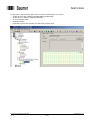
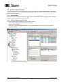
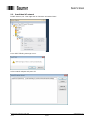
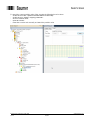
To watch the current position value of the encoder the following has to be done:
- double-click on “Box 1 (Baumer EAx580 EtherCAT Encoder)”
- double-click on “TPDO 1 mapping parameter”
- click on “Position value”
- open tab “Online”
- rotate the encoder axis manually and watch the position value

Baumer_EAx_EtherCAT_EN_MNL www.baumer.com
02.20 20/121
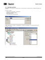
4.6. Run Mode (real-time)
If you want to run the EtherCAT Master with a cycle time below 1 millisecond the so-called “Run Mode” can
be used.
Proceed as follows:
- double-click on “SYSTEM - Configuration”
- right-click on “Additional Tasks”
- select “Append Task”
- confirm following message with OK
Adjust „Base Time“ (“SYSTEM – Configuration” -> “Real-Time Settings”) to 100 microseconds (as an
example) as follows:
Page is loading ...
Page is loading ...
Page is loading ...
Page is loading ...
Page is loading ...
Page is loading ...
Page is loading ...
Page is loading ...
Page is loading ...
Page is loading ...
Page is loading ...
Page is loading ...
Page is loading ...
Page is loading ...
Page is loading ...
Page is loading ...
Page is loading ...
Page is loading ...
Page is loading ...
Page is loading ...
Page is loading ...
Page is loading ...
Page is loading ...
Page is loading ...
Page is loading ...
Page is loading ...
Page is loading ...
Page is loading ...
Page is loading ...
Page is loading ...
Page is loading ...
Page is loading ...
Page is loading ...
Page is loading ...
Page is loading ...
Page is loading ...
Page is loading ...
Page is loading ...
Page is loading ...
Page is loading ...
Page is loading ...
Page is loading ...
Page is loading ...
Page is loading ...
Page is loading ...
Page is loading ...
Page is loading ...
Page is loading ...
Page is loading ...
Page is loading ...
Page is loading ...
Page is loading ...
Page is loading ...
Page is loading ...
Page is loading ...
Page is loading ...
Page is loading ...
Page is loading ...
Page is loading ...
Page is loading ...
Page is loading ...
Page is loading ...
Page is loading ...
Page is loading ...
Page is loading ...
Page is loading ...
Page is loading ...
Page is loading ...
Page is loading ...
Page is loading ...
Page is loading ...
Page is loading ...
Page is loading ...
Page is loading ...
Page is loading ...
Page is loading ...
Page is loading ...
Page is loading ...
Page is loading ...
Page is loading ...
Page is loading ...
Page is loading ...
Page is loading ...
Page is loading ...
Page is loading ...
Page is loading ...
Page is loading ...
Page is loading ...
Page is loading ...
Page is loading ...
Page is loading ...
Page is loading ...
Page is loading ...
Page is loading ...
Page is loading ...
Page is loading ...
Page is loading ...
Page is loading ...
Page is loading ...
Page is loading ...
Page is loading ...
-
 1
1
-
 2
2
-
 3
3
-
 4
4
-
 5
5
-
 6
6
-
 7
7
-
 8
8
-
 9
9
-
 10
10
-
 11
11
-
 12
12
-
 13
13
-
 14
14
-
 15
15
-
 16
16
-
 17
17
-
 18
18
-
 19
19
-
 20
20
-
 21
21
-
 22
22
-
 23
23
-
 24
24
-
 25
25
-
 26
26
-
 27
27
-
 28
28
-
 29
29
-
 30
30
-
 31
31
-
 32
32
-
 33
33
-
 34
34
-
 35
35
-
 36
36
-
 37
37
-
 38
38
-
 39
39
-
 40
40
-
 41
41
-
 42
42
-
 43
43
-
 44
44
-
 45
45
-
 46
46
-
 47
47
-
 48
48
-
 49
49
-
 50
50
-
 51
51
-
 52
52
-
 53
53
-
 54
54
-
 55
55
-
 56
56
-
 57
57
-
 58
58
-
 59
59
-
 60
60
-
 61
61
-
 62
62
-
 63
63
-
 64
64
-
 65
65
-
 66
66
-
 67
67
-
 68
68
-
 69
69
-
 70
70
-
 71
71
-
 72
72
-
 73
73
-
 74
74
-
 75
75
-
 76
76
-
 77
77
-
 78
78
-
 79
79
-
 80
80
-
 81
81
-
 82
82
-
 83
83
-
 84
84
-
 85
85
-
 86
86
-
 87
87
-
 88
88
-
 89
89
-
 90
90
-
 91
91
-
 92
92
-
 93
93
-
 94
94
-
 95
95
-
 96
96
-
 97
97
-
 98
98
-
 99
99
-
 100
100
-
 101
101
-
 102
102
-
 103
103
-
 104
104
-
 105
105
-
 106
106
-
 107
107
-
 108
108
-
 109
109
-
 110
110
-
 111
111
-
 112
112
-
 113
113
-
 114
114
-
 115
115
-
 116
116
-
 117
117
-
 118
118
-
 119
119
-
 120
120
-
 121
121


Baumer EAL580-SC - EtherCAT Owner's manual
- Type
- Owner's manual
- This manual is also suitable for
Ask a question and I''ll find the answer in the document
Finding information in a document is now easier with AI
Related papers
-
Baumer EAL580-SC - EtherNet/IP Owner's manual
-
Baumer GBAMS Owner's manual
-
Baumer EAL580-B - PROFINET Owner's manual
-
-
-
-
-
Baumer PF20S Operating instructions
-
Baumer DLM40-SO Installation and Operating Instructions
-
Other documents
-
 ICPDAS ECAT-2094 Series Ethercat Slave 4 Axis Stepper Motor Controller Driver User guide
-
ICP DAS USA ECAT-2610 Quick Start
-
-
 CKD RT Series (EtherCAT) User manual
-
ICP ECAT-2611 Quick Start
-
 halstrup-walcher PS 32 EC Series User manual
-
-
ESD CAN-EtherCAT EtherCAT-CAN Gateway Owner's manual
-
-


