Form No. 3356-902 Rev A
Commercial Walk-Behind
Mower
For Floating Deck, Pistol Grip, Hydro
with 36in, 40in, 48in or 52in TURBO
FORCE® Cutting Unit
Model No. 30284 —Serial No. 270000001 and Up
Model No. 30286 —Serial No. 270000001 and Up
Model No. 30288 —Serial No. 270000001 and Up
Model No. 30289 —Serial No. 270000001 and Up
Register your product at www.Toro.com Original Instructions (EN)

Warning
CALIFORNIA
Pr oposition 65 W ar ning
T he engine exhaust fr om this pr oduct
contains chemicals kno wn to the State of
Calif or nia to cause cancer , bir th defects, or
other r epr oducti v e har m.
T his spark ignition system complies with Canadian
ICES-002
Important: T his engine is not equipped
with a spar k ar r ester muf fler . It is a
violation of Calif or nia Public R esource Code
Section 4442 to use or operate the engine
on an y f or est-co v er ed, br ush-co v er ed, or
g rass-co v er ed land. Other states or federal
ar eas may ha v e similar la ws.
T he enclosed Engine Owner’ s Man ual is
supplied f or inf or mation r egarding the US
En vir onmental Pr otection Agency (EP A) and
the Calif or nia Emission Contr ol R egulation of
emission systems, maintenance, and w ar ranty .
R eplacements may be order ed thr ough the
engine man uf actur er .
Introduction
R ead this infor mation carefully to lear n ho w to
operate and maintain y our product properly and
to a v oid injur y and product damag e . Y ou are
responsible for operating the product properly
and safely .
Y ou ma y contact T oro directly at www .T oro .com
for product and accessor y infor mation, help
finding a dealer , or to register y our product.
W henev er y ou need ser vice , g en uine T oro par ts ,
or additional infor mation, contact an A uthorized
Ser vice Dealer or T oro Customer Ser vice and ha v e
the model and serial n umbers of y our product
ready . Figure 1 identifies the location of the model
and serial n umbers on the product. W rite the
n umbers in the space pro vided.
Figure 1
1. Location of the model and serial numbers
Model No.
Serial No.
T his man ual identifies potential hazards and has
safety messag es identified b y the follo wing w ords:
• Danger signals an extreme hazard that will
cause serious injur y or death if y ou do not
follo w the recommended precautions .
• W ar ning signals a hazard that may cause
serious injur y or death if y ou do not follo w the
recommended precautions .
• Caution signals a hazard that ma y cause minor
or moderate injur y if y ou do not follo w the
recommended precautions .
T his man ual uses tw o other w ords to highlight
infor mation. Impor tant calls attention to special
mec hanical infor mation and Note emphasizes
g eneral infor mation w or th y of special attention.
Contents
Introduction . . . . . . . . . . . . . . . . . . . . . . . . . . . . . . . . . . . . . . . . . . . . . . . . . . . . . . . 2
Safety . . . . . . . . . . . . . . . . . . . . . . . . . . . . . . . . . . . . . . . . . . . . . . . . . . . . . . . . . . . . . . . . . . 4
Safe Operating Practices . . . . . . . . . . . . . . . . . . . . . . 4
T oro Mo w er Safety . . . . . . . . . . . . . . . . . . . . . . . . . . . . . . 5
Slope Char t . . . . . . . . . . . . . . . . . . . . . . . . . . . . . . . . . . . . . . . . . 7
Safety and Instr uctional Decals . . . . . . . . . . . . 8
Product Ov er view . . . . . . . . . . . . . . . . . . . . . . . . . . . . . . . . . . . . . . . . . . . . . 12
Controls . . . . . . . . . . . . . . . . . . . . . . . . . . . . . . . . . . . . . . . . . . . 12
Specifications . . . . . . . . . . . . . . . . . . . . . . . . . . . . . . . . . . . 13
Operation . . . . . . . . . . . . . . . . . . . . . . . . . . . . . . . . . . . . . . . . . . . . . . . . . . . . . . . . . . 14
Adding Fuel . . . . . . . . . . . . . . . . . . . . . . . . . . . . . . . . . . . . . . 14
Chec king the Engine Oil Lev el . . . . . . . . . . . 15
T hink Safety First . . . . . . . . . . . . . . . . . . . . . . . . . . . . . . 15
© 2006—The Toro® Company
8111 Lyndale Avenue South
Bloomington, MN 55420
2
Contact us at www.Toro.com.
Printed in the USA.
All Rights Reserved

Operating the P arking Brak e . . . . . . . . . . . . . . 15
Star ting and Stopping the
Engine . . . . . . . . . . . . . . . . . . . . . . . . . . . . . . 16
Operating the Neutral Loc ks . . . . . . . . . . . . . . 16
Operating the Mo w er Blade
Control (PTO) . . . . . . . . . . . . . . . . . . . 17
T he Safety Interloc k System . . . . . . . . . . . . . . . 18
Dri ving the Mac hine F orw ard and
Bac kw ard . . . . . . . . . . . . . . . . . . . . . . . . . . 18
Bringing the Mac hine to the
Neutral P osition . . . . . . . . . . . . . . . . 19
Stopping the Mac hine . . . . . . . . . . . . . . . . . . . . . . . . 19
Pushing the Mac hine b y Hand . . . . . . . . . . . . 19
T ranspor ting Mac hines . . . . . . . . . . . . . . . . . . . . . . 20
Side Disc harging or Mulc hing the
Grass . . . . . . . . . . . . . . . . . . . . . . . . . . . . . . . . . 20
Adjusting the Height-of-Cut . . . . . . . . . . . . . . 20
Adjusting the Anti-Scalp
R ollers . . . . . . . . . . . . . . . . . . . . . . . . . . . . . . . 21
Adjusting the Handle Height . . . . . . . . . . . . . . 22
Adjusting the Flo w Baffle . . . . . . . . . . . . . . . . . . . 23
P ositioning the Flo w Baffle . . . . . . . . . . . . . . . . 23
Using the Mid-Size W eight . . . . . . . . . . . . . . . . . 25
Maintenance . . . . . . . . . . . . . . . . . . . . . . . . . . . . . . . . . . . . . . . . . . . . . . . . . . . . . . 27
R ecommended Maintenance
Sc hedule(s) . . . . . . . . . . . . . . . . . . . . . . . . . . . . . . . 27
Lubrication . . . . . . . . . . . . . . . . . . . . . . . . . . . . . . . . . . . . . . . . . . . . . . . . 28
Ho w to Grease . . . . . . . . . . . . . . . . . . . . . . . . . . . . . . . . . . 28
Lubricating the Bearings . . . . . . . . . . . . . . . . . . . . 28
Greasing the PTO Dri v e Belt Idler
and Mo w er Dec k Belt
Idler . . . . . . . . . . . . . . . . . . . . . . . . . . . . . . . . . . 28
Engine Maintenance . . . . . . . . . . . . . . . . . . . . . . . . . . . . . . . . . . 29
Ser vicing the Air Cleaner . . . . . . . . . . . . . . . . . . . 29
Ser vicing the Engine Oil . . . . . . . . . . . . . . . . . . . . 30
Ser vicing the Spark Plugs . . . . . . . . . . . . . . . . . . . 31
Fuel System Maintenance . . . . . . . . . . . . . . . . . . . . . . . . . . 33
Draining the Fuel T ank . . . . . . . . . . . . . . . . . . . . . . 33
Ser vicing the Fuel Filter . . . . . . . . . . . . . . . . . . . . . 33
Electrical System Maintenance . . . . . . . . . . . . . . . . . . . 34
Ser vicing the Batter y . . . . . . . . . . . . . . . . . . . . . . . . . . 34
Ser vicing the Fuses . . . . . . . . . . . . . . . . . . . . . . . . . . . . 36
Dri v e System Maintenance . . . . . . . . . . . . . . . . . . . . . . . . . 37
Adjusting the Speed Control
Linkag e . . . . . . . . . . . . . . . . . . . . . . . . . . . . . 37
T emporar y Neutral Stud
Adjustment . . . . . . . . . . . . . . . . . . . . . . . 38
Adjusting the Hy dro Control
Linkag es . . . . . . . . . . . . . . . . . . . . . . . . . . . . 39
Adjusting the Neutral Stud . . . . . . . . . . . . . . . . . 41
Adjusting the Control R od . . . . . . . . . . . . . . . . . 42
Adjusting the T rac king . . . . . . . . . . . . . . . . . . . . . . 43
Adjusting the T raction Spring . . . . . . . . . . . . . 43
Chec king the Tire Pressure . . . . . . . . . . . . . . . . . 43
R e placing the Caster W heel F ork
Bushings . . . . . . . . . . . . . . . . . . . . . . . . . . . 44
Ser vicing the Caster W heel and
Bearings . . . . . . . . . . . . . . . . . . . . . . . . . . . . 45
Adjusting the Electric Clutc h . . . . . . . . . . . . . 45
Cooling System Maintenance . . . . . . . . . . . . . . . . . . . . . 45
Cleaning the Air Intak e Screen . . . . . . . . . . . 45
Brak e Maintenance . . . . . . . . . . . . . . . . . . . . . . . . . . . . . . . . . . . . 46
Ser vicing the Brak e . . . . . . . . . . . . . . . . . . . . . . . . . . . . 46
Belt Maintenance . . . . . . . . . . . . . . . . . . . . . . . . . . . . . . . . . . . . . . . 46
R e placing the Mo w er Belt . . . . . . . . . . . . . . . . . . 46
R e placing the PTO Dri v e Belt . . . . . . . . . . . . 47
Adjusting the PTO Dri v e Belt Idler
Spring Anc hor . . . . . . . . . . . . . . . . . . . 49
R e placing the Pump Dri v e
Belt . . . . . . . . . . . . . . . . . . . . . . . . . . . . . . . . . . . 49
Hy draulic System Maintenance . . . . . . . . . . . . . . . . . . 50
Ser vicing the Hy draulic
System . . . . . . . . . . . . . . . . . . . . . . . . . . . . . . . 50
Mo w er Dec k Maintenance . . . . . . . . . . . . . . . . . . . . . . . . . 52
Ser vicing the Cutting Blades . . . . . . . . . . . . . . . 52
Cor recting the Mo w er Quality of
Cut . . . . . . . . . . . . . . . . . . . . . . . . . . . . . . . . . . . . 55
F rame Set Up . . . . . . . . . . . . . . . . . . . . . . . . . . . . . . . . . . . . 55
Chec king the Mo w er Dec k
F ront-to-R ear Pitc h . . . . . . . . . . . 57
Changing the Mo w er Dec k
F ront-to-R ear Pitc h . . . . . . . . . . . 58
Chec king the Mo w er Dec k
Side-to-Side Height . . . . . . . . . . . 58
Changing the Mo w er Dec k
Side-to-Side Height . . . . . . . . . . . 58
Matc hing Height of Cut . . . . . . . . . . . . . . . . . . . . . 58
R e placing the Grass Deflector . . . . . . . . . . . . 59
Cleaning . . . . . . . . . . . . . . . . . . . . . . . . . . . . . . . . . . . . . . . . . . . . . . . . . . . . 60
Cleaning Under the Mo w er . . . . . . . . . . . . . . . . 60
W aste Disposal . . . . . . . . . . . . . . . . . . . . . . . . . . . . . . . . . . 60
Storag e . . . . . . . . . . . . . . . . . . . . . . . . . . . . . . . . . . . . . . . . . . . . . . . . . . . . . . . . . . . . . . 61
Cleaning and Storag e . . . . . . . . . . . . . . . . . . . . . . . . . 61
T roubleshooting . . . . . . . . . . . . . . . . . . . . . . . . . . . . . . . . . . . . . . . . . . . . . . . . 62
Sc hematics . . . . . . . . . . . . . . . . . . . . . . . . . . . . . . . . . . . . . . . . . . . . . . . . . . . . . . . . 65
3

Safety
Note: T he addition of attac hments made b y
other man ufacturers that do not meet American
National Standards Institute cer tification will cause
noncompliance of this mac hine .
Improper use or maintenance b y the operator or
o wner can result in injur y . T o reduce the potential
for injur y , comply with these safety instr uctions
and alw a ys pa y attention to the safety aler t symbol
, whic h means CA UTION , W ARNING , or
D ANGER-“personal safety instr uction." F ailure
to comply with the instr uction ma y result in
personal injur y or death.
Safe Operating Practices
T he follo wing instr uctions are from ANSI
standard B71.4-2004.
Training
• R ead the Operator’ s Man ual and other training
material. If the operator(s) or mec hanic(s) can
not read English it is the o wner’ s responsibility
to explain this material to them.
• Become familiar with the safe operation of the
equipment, operator controls , and safety signs .
• All operators and mec hanics should be trained.
T he o wner is responsible for training the users .
• Nev er let c hildren or untrained people operate
or ser vice the equipment. Local regulations
ma y restrict the ag e of the operator .
• T he o wner/user can prev ent and is responsible
for accidents or injuries occur ring to himself
or herself , other people or proper ty .
Preparation
• Ev aluate the ter rain to deter mine what
accessories and attac hments are needed to
properly and safely perfor m the job . Only use
accessories and attac hments appro v ed b y the
man ufacturer .
• W ear appropriate clothing including hard hat,
safety glasses and hearing protection. Long
hair , loose clothing or jew elr y ma y g et tangled
in mo ving par ts .
• Inspect the area where the equipment is to be
used and remo v e all objects suc h as roc ks , to ys
and wire whic h can be thro wn b y the mac hine .
• Use extra care when handling g asoline and
other fuels . T hey are flammable and v apors
are explosi v e .
– Use only an appro v ed container
– Nev er remo v e g as cap or add fuel with
engine r unning . Allo w engine to cool
before refueling . Do not smok e .
– Nev er refuel or drain the mac hine indoors .
• Chec k that operator’ s presence controls ,
safety switc hes and shields are attac hed and
functioning properly . Do not operate unless
they are functioning properly .
Operation
• Nev er r un an engine in an enclosed area.
• Only operate in g ood light, k ee ping a w a y from
holes and hidden hazards .
• Be sure all dri v es are in neutral and parking
brak e is eng ag ed before star ting engine . Only
star t engine from the operator’ s position.
• Be sure of y our footing while using this
mac hine , especially when bac king up . W alk,
don ’ t r un. Nev er operate on w et g rass .
R educed footing could cause slipping .
• Slo w do wn and use extra care on hillsides . Be
sure to tra v el side to side on hillsides . T urf
conditions can affect the mac hine’ s stability .
Use caution while operating near drop-offs .
• Slo w do wn and use caution when making tur ns
and when c hanging directions on slopes .
• Nev er raise dec k with the blades r unning .
• Nev er operate with the PTO shield, or other
guards not securely in place . Be sure all
interloc ks are attac hed, adjusted properly , and
functioning properly .
• Nev er operate with the disc harg e deflector
raised, remo v ed or altered, unless using a g rass
catc her .
• Do not c hang e the engine g o v er nor setting or
o v erspeed the engine .
• Stop on lev el g round, diseng ag e dri v es , eng ag e
parking brak e (if pro vided), shut off engine
before lea ving the operator’ s position for any
reason including emptying the catc hers or
unclog ging the c hute .
4

• Stop equipment and inspect blades after
striking objects or if an abnor mal vibration
occurs . Mak e necessar y re pairs before
resuming operations .
• K ee p hands and feet a w a y from the cutting
unit.
• Look behind and do wn before bac king up to
be sure of a clear path.
• K ee p pets and b ystanders a w a y .
• Slo w do wn and use caution when making tur ns
and crossing roads and sidew alks . Stop blades
if not mo wing .
• Be a w are of the mo w er disc harg e direction and
do not point it at any one .
• Do not operate the mo w er under the influence
of alcohol or dr ugs .
• Use care when loading or unloading the
mac hine into or from a trailer or tr uc k.
• Use care when approac hing blind cor ners ,
shr ubs , trees , or other objects that ma y obscure
vision.
Maintenance and storage
• Diseng ag e dri v es , set parking brak e , stop
engine and remo v e k ey or disconnect spark
plug wire . W ait for all mo v ement to stop
before adjusting, cleaning or re pairing .
• Clean g rass and debris from cutting unit,
dri v es , m ufflers , and engine to help prev ent
fires . Clean up oil or fuel spillag e .
• Let engine cool before storing and do not store
near flame .
• Shut off fuel while storing or transpor ting . Do
not store fuel near flames or drain indoors .
• P ark mac hine on lev el g round. Set parking
brak e . Nev er allo w untrained personnel to
ser vice mac hine .
• Use jac k stands to suppor t components when
required.
• Carefully release pressure from components
with stored energ y .
• Disconnect the batter y or remo v e spark plug
wire before making any re pairs . Disconnect
the neg ati v e ter minal first and the positi v e last.
R econnect the positi v e first and neg ati v e last.
• Use care when c hec king blades . W rap the
blade(s) or w ear glo v es , and use caution when
ser vicing them. Only re place blades . Nev er
straighten or w eld them.
• K ee p hands and feet a w a y from mo ving par ts .
If possible , do not mak e adjustments with the
engine r unning .
• K ee p all par ts in g ood w orking condition and
all hardw are tightened. R e place all w or n or
damag ed decals .
Toro Mower Safety
T he follo wing list contains safety infor mation
specific to T oro products and other safety
infor mation y ou m ust kno w .
T his product is capable of amputating hands and
feet and thro wing objects . Alw a ys follo w all safety
instr uctions to a v oid serious injur y or death.
T his product is designed for cutting and recycling
g rass or , when equipped with a g rass bag g er , for
catc hing cut g rass . Any use for pur poses other
than these could pro v e dang erous to user and
b ystanders .
General Operation
• Be sure the area is clear of other people before
mo wing . Stop the mac hine if any one enters
the area.
• Do not touc h equipment or attac hment par ts
whic h ma y be hot from operation. Allo w to
cool before attempting to maintain, adjust or
ser vice .
• Use only T oro appro v ed attac hments .
W ar ranty ma y be v oided if used with
unappro v ed attac hments .
• Chec k carefully for o v erhead clearances (i.e .
branc hes , doorw a ys , electrical wires) before
operating under any objects and do not contact
them.
Slope Operation
All slopes and ramps require extra caution. If y ou
feel uneasy on a slope , do not mo w it.
• R emo v e obstacles suc h as roc ks , tree limbs , etc .
from the mo wing area.
• W atc h for holes , r uts or bumps . T all g rass can
hide obstacles .
• Use caution near drop-offs , ditc hes , or
embankments . T he mac hine could suddenly
5

tur n o v er if a wheel g oes o v er the edg e of a
cliff or ditc h, or if an edg e ca v es in.
• Use extra care with g rass catc hers or other
attac hments . T hese can c hang e the stability of
the mac hine .
• K ee p all mo v ement on slopes slo w and g radual.
Do not mak e sudden c hang es in speed or
direction.
• Mo w slopes side to side .
• Do not mo w slopes g reater than 15 deg rees .
Service
• Nev er store the mac hine or fuel container
inside where there is an open flame , suc h as
near a w ater heater or fur nace .
• K ee p n uts and bolts tight, especially the blade
attac hment bolts . K ee p equipment in g ood
condition.
• Nev er tamper with safety devices . Chec k safety
systems for proper operation before eac h use .
• Use only g en uine re placement par ts to ensure
that original standards are maintained.
• Chec k brak e operation frequently . Adjust and
ser vice as required.
6

Slope Chart
7

Safety and Instructional
Decals
Safety decals and instr uctions are easily visible to the operator and are located near any
area of potential dang er . R e place any decal that is damag ed or lost.
1-523552
43-8480
66-1340
68-8340
95-2814
98-0776
98-4387
1. Warning—wear hearing protection.
98-5954
8

Battery Symbols
Some or all of these symbols are on your battery
1. Explosion hazard 6. Keep bystanders a safe
distance from the battery.
2. No re, open ame, or
smoking.
7. Wear eye protection;
explosive gases can cause
blindness and other injuries
3. Caustic liquid/chemical
burn hazard
8. Battery acid can cause
blindness or severe burns.
4. Wear eye protection
9. Flush eyes immediately
with water and get medical
help fast.
5. Read the Operator’s
Manual.
10. Contains lead; do not
discard.
104-8185
104-8186
104-8569
105-4109
105-4110
105-7798
106-0635
106-0699
Manufacturer’s Mark
1. Indicates the blade is identied as a part from the original
machine manufacturer.
9

110-2067
110-2068
1. Read the Operator’s Manual .
112-8720
10

106-5515
1. Keep bystanders a safe distance from the machine.
7. Engine—run
2. Do not allow bystanders to be hit by thrown objects.
8. Hour meter
3. Do not operate the mower with the deector up or removed. 9. To park, squeeze the drive levers and rotate the neutral locks
forward.
4. Stop the engine and pick up debris before operating. 10. To drive, rotate the neutral locks and slowly release the drive
levers.
5. Mower can cut hands or feet. 11. To place the machine in neutral, squeeze the drive levers and
rotate the neutral locks backward.
6. Engine—stop
12. Power take-off (PTO)
110-4953
1. Fast
2. Continuous variable setting 3. Slow 4. Choke
11

Product Overview
Figure 2
1. Side discharge chute 4. Gas tank
2. Mower deck 5. Controls
3. Engine
6. Front caster
Controls
Become familiar with all the controls ( Figure 3 )
before y ou star t the engine and operate the
mac hine .
Figure 3
1. Throttle control 7. Neutral lock
2. Speed control lever 8. Operator Presence Control
levers (OPC)
3. Choke 9. Handle
4. Ignition switch
10. Drive Lever
5. Hour meter
11. Fuel shut-off valve
6. Blade control switch (PTO)
Throttle Control
T he throttle control has tw o positions: F ast and
Slo w .
Choke
Use the c hok e to star t a cold engine .
Operator Presence Control (OPC)
Levers
W hen y ou squeeze the OPC lev ers ag ainst the
handles , the OPC system senses that the operator
is in the nor mal operating position. W hen y ou
release the OPC lev ers , the OPC system senses
that the operator has left the nor mal operating
position, and the system will stop the engine if
either the speed control lev er is not in the neutral
position or the blade control (PTO) switc h is
eng ag ed.
Blade Control Switch (PTO)
T he blade control switc h (PTO) is used to eng ag e
the electric clutc h to dri v e the mo w er blades with
the OPC lev ers pressed ag ainst the handles . Pull
the switc h up to eng ag e the blades . T o diseng ag e
the blades , briefly release the OPC lev ers .
Ignition Switch
T his switc h is used to star t the mo w er engine and
has three positions: Star t, R un and Of f .
Speed Control Lever
T his mac hine has a v ariable speed control with a
neutral position. T his controls ho w fast or slo w
the mac hine will tra v el forw ard.
Drive Levers
R elease dri v e lev ers to eng ag e forw ard traction
operation and squeeze the lev ers until an increase
in force is felt to g o into neutral position and
contin ue to squeeze to g o in rev erse . Squeeze
right side of dri v e lev er to tur n right and left side
to tur n left.
Neutral Lock
Squeeze dri v e lev ers bac k until an increase in force
is felt and mo v e loc ks to the rear for neutral loc k.
12

Fuel Shut-off Valve
Close the fuel shut-off v alv e (under fuel tank )
when transpor ting or storing mo w er .
Hour Meter
Sho ws the total hours the mac hine has been
operated. T his operates only when the mo w er
blades are operating .
T he hour meter will flash 3 hours before and after
a ser vice inter v al. T he ser vice inter v als are set for
the first 8 hours , ev er y 100 hours there after , and
ev er y 400 hours .
Note: Mak e sure maintenance is done at
all recommended inter v als sho wn in the
R ecommended Maintenance Sc hedule .
Attachments/Accessories
A selection of T oro appro v ed attac hments and
accessories are a v ailable for use with the mac hine
to enhance and expand its capabilities . Contact
y our A uthorized Ser vice Dealer or Distributor or
g o to www .T oro .com for a list of all appro v ed
attac hments and accessories .
Specications
Note: Specifications and design are subject to
c hang e without notice .
36 inc h mo w ers:
Width with deector down
51–1/8 inches (130 cm)
Length
84–1/2 inches (215 cm)
Height with handle in
lowest position
41–1/2 inches (106 cm)
Weight
677 lb (307 kg)
40 inc h mo w ers:
Width with deector down
55–1/2 inches (141 cm)
Length
81–1/3 inches (207 cm)
Height with handle in
lowest position
41–1/2 inches (106 cm)
Weight
677 lb (307 kg)
48 inc h mo w ers:
Width with deector down
63–1/2 inches (161 cm)
Length
83–3/4 inches (213 cm)
Height with handle in
lowest position
41–1/2 inches (106 cm)
Weight
692 lb (314 kg)
52 inc h mo w ers:
Width with deector down
67–5/8 inches (171.7 cm)
Length
83–3/4 inches (213 cm)
Height with handle in
lowest position
41–1/2 inches (106 cm)
Weight
731 lb (332 kg)
13

Operation
Adding Fuel
Use Unleaded R egular Gasoline suitable for
automoti v e use (85 pump octane minim um).
Leaded regular g asoline ma y be used if unleaded
regular is not a v ailable .
Important: Nev er use methanol, gasoline
containing methanol, or gasohol containing
mor e than 10% ethanol because the fuel
system could be dama ged. Do not mix oil
with gasoline.
In cer tain conditions, gasoline is extr emel y
flamma ble and highl y explosi v e. A fir e or
explosion fr om gasoline can bur n y ou and
other s and can dama ge pr oper ty .
• Fill the fuel tank outdoor s, in an open
ar ea, when the engine is cold. W ipe up
an y gasoline that spills.
• Nev er fill the fuel tank inside an enclosed
trailer .
• Do not fill the fuel tank completel y full.
Add gasoline to the fuel tank until the
lev el is 1/4 to 1/2 inch (6 to 13 mm)
belo w the bottom of the filler neck. T his
empty space in the tank allo ws gasoline
to expand.
• Nev er smok e when handling gasoline,
and stay a w ay fr om an open flame or
wher e gasoline fumes may be ignited by
a spar k.
• Stor e gasoline in an appr o v ed container
and k eep it out of the r each of childr en.
Nev er buy mor e than a 30-day suppl y of
gasoline.
• Do not operate without entir e exhaust
system in place and in pr oper w or king
condition.
In cer tain conditions during fueling , static
electricity can be r eleased causing a spar k
which can ignite the gasoline v apor s. A fir e
or explosion fr om gasoline can bur n y ou and
other s and can dama ge pr oper ty .
• Al w ays place gasoline container s on the
g r ound a w ay fr om y our v ehicle bef or e
filling .
• Do not fill gasoline container s inside
a v ehicle or on a tr uck or trailer bed
because interior car pets or plastic tr uck
bed liner s may insulate the container and
slo w the loss of an y static charge.
• W hen practical, r emo v e gas-po w er ed
equipment fr om the tr uck or trailer and
r efuel the equipment with its wheels on
the g r ound.
• If this is not possible, then r efuel such
equipment on a tr uck or trailer fr om a
por ta ble container , rather than fr om a
gasoline dispenser nozzle.
• If a gasoline dispenser nozzle must be
used, k eep the nozzle in contact with the
rim of the fuel tank or container opening
at all times until fueling is complete.
Gasoline is har mful or f atal if s w allo w ed.
Long-ter m exposur e to v apor s can cause
serious injur y and illness.
• A v oid pr olonged br eathing of v apor s.
• K eep f ace a w ay fr om nozzle and gas tank
or conditioner opening .
• K eep gas a w ay fr om ey es and skin.
Using Stabilizer/Conditioner
Use a fuel stabilizer/conditioner in the mac hine to
pro vide the follo wing benefits:
• K ee ps g asoline fresh during storag e of 90 da ys
or less . F or long er storag e it is recommended
that the fuel tank be drained.
14

• Cleans the engine while it r uns
• Eliminates gum-lik e v ar nish buildup in the fuel
system, whic h causes hard star ting
Important: Do not use fuel additi v es
containing methanol or ethanol.
Add the cor rect amount of g as
stabilizer/conditioner to the g as .
Note: A fuel stabilizer/conditioner is most
effecti v e when mix ed with fresh g asoline . T o
minimize the c hance of v ar nish de posits in the
fuel system, use fuel stabilizer at all times .
Filling the Fuel Tank
1. Shut the engine off and set the parking brak e .
2. Clean around fuel tank cap and remo v e the
cap . Add unleaded regular g asoline to fuel
tank, until the lev el is 1/4 to 1/2 inc h (6 to 13
mm) belo w the bottom of the filler nec k. T his
space in the tank allo ws g asoline to expand.
Do not fill the fuel tank completely full.
3. Install fuel tank cap securely . Wipe up any
g asoline that ma y ha v e spilled.
Checking the Engine Oil
Level
Before y ou star t the engine and use the mac hine ,
c hec k the oil lev el in the engine crankcase; refer to
Chec king Oil Lev el in Engine Maintenance .
Note: Deter mine the left and right sides of the
mac hine from the nor mal operating position.
Think Safety First
Carefully read all the safety instr uctions and decals
in the safety section. Kno wing this infor mation
could help y ou or any b ystanders a v oid injur y .
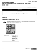
T he use of protecti v e equipment for eyes , hearing,
feet and head is recommended.
T his machine pr oduces sound lev els in
ex cess of 85 dB A at the operator’ s ear and
can cause hearing loss thr ough extended
periods of exposur e.
W ear hearing pr otection when operating
this machine.
Figure 4
1. Warning—wear hearing protection.
Operating the Parking
Brake
Alw a ys set the parking brak e when y ou stop the
mac hine or lea v e it unattended. Before eac h use ,
c hec k the parking brak e for proper operation.
If the parking brak e does not hold securely , adjust
it. R efer to Ser vicing the P arking Brak e .
Childr en or bystander s may be injur ed if
they mo v e or attempt to operate the machine
while it is unattended.
Al w ays r emo v e the ignition k ey and set the
par king brak e when lea ving the machine
unattended, ev en if just f or a few min utes.
Setting the Parking Brake
Pull the parking brak e lev er rearw ard ( Figure 5 ).
15

Figure 5
1. Parking brake lever (in the
released position)
2. Parking brake lever (in the
engaged position)
Releasing the Parking Brake
Push the parking brak e lev er forw ard.
Starting and Stopping the
Engine
Starting the Engine
1. Connect the wires to the spark plugs .
2. Open the fuel v alv e .
3. Mo v e the speed control lev er to neutral.
4. Set the neutral loc ks .
5. Set the parking brak e .
6. Mo v e the throttle control to fast and mo v e the
c hok e lev er to the on position before star ting a
cold engine ( Figure 6 ).
Note: A w ar m or hot engine ma y not require
c hoking . T o star t a w ar m engine , mo v e throttle
control to the fast position.
Figure 6
1. Ignition switch 3. Choke
2. Throttle lever
7. T ur n the ignition k ey to the star t position to
energize the star ter . W hen the engine star ts ,
release the k ey .
Note: Do not eng ag e the star ter for more
than 5 seconds at a time . If the engine fails to
star t, allo w for a 15 second cool-do wn period
betw een attempts . F ailure to follo w these
instr uctions can bur n out the star ter motor .
8. W hen engine star ts , mo v e the throttle control
betw een the fast and slo w position and mo v e
the c hok e lev er to the off position. Allo w the
engine to w ar m up and then mo v e the throttle
control to the fast position.
Stopping the Engine
1. Mo v e dri v e lev ers to neutral and set neutral
loc ks .
2. Mo v e the throttle lev er to slo w ( Figure 6 ).
3. Mo v e the speed control lev er to neutral and
release the OPC lev ers to diseng ag e the mo w er .
4. If the engine has been w orking hard or is hot,
let the engine idle for 30 to 60 seconds before
tur ning the engine off .
5. T o stop the engine , tur n the ignition k ey to off .
Important: Mak e sur e fuel shut of f v alv e
is closed bef or e transpor ting or storing
machine, as fuel leaka ge may occur . Bef or e
storing machine, pull wir e of f spar k plug(s)
to pr ev ent possibility of accidental star ting .
Operating the Neutral Locks
Alw a ys set the neutral loc k when y ou stop
the mac hine . Set the parking brak e if it is left
unattended.
16

Setting the Neutral Lock
1. Squeeze the dri v e lev ers bac k until an increase
in force is felt.
2. Place thumbs on the upper par t of the loc ks
and mo v e them bac k ( Figure 7 ).
Figure 7
1. Handle 4. Drive lever
2. Neutral lock 5. Full speed forward position
3. Neutral position
6. Reverse position
Releasing the Neutral Lock
1. Squeeze the dri v e lev ers bac k until an increase
in force is felt.
2. Place thumbs on the upper par t of loc ks and
mo v e them forw ard until the pins are in the
forw ard slot ( Figure 8 ).
Figure 8
1. Handle 4. Pin in full speed forward
position
2. Neutral lock 5. Handle
3. Drive lever 6. Forward slot
Operating the Mower Blade
Control (PTO)
T he blade control knob (PTO) is used in
conjunction with the Operator Presence Control
(OPC) lev ers to eng ag e and diseng ag e the mo w er
blades .
Engaging the Mower Blades (PTO)
1. T o eng ag e blades , squeeze the Operator
Presence Control (OPC) lev ers ag ainst handle
g rips ( Figure 9 ).
2. Pull the blade switc h (PTO) up and release it
while holding the OPC lev ers ag ainst handle
g rip .
Figure 9
1. Handle
3. Blade control switch (PTO)
2. Operator Presence Control
levers (OPC)
4. Drive Lever
Disengaging the Mower Blades (PTO)
R elease the Operator Presence Control (OPC)
lev ers to stop the blades ( Figure 9 ).
Note: T he engine will kill if the OPC lev ers are
released with the mo w er r unning and the speed
control lev er is not in neutral position.
17

The Safety Interlock System
If safety inter lock s witches ar e disconnected
or dama ged the machine could operate
unexpectedl y causing per sonal injur y .
• Do not tamper with the inter lock
s witches.
• Check the operation of the inter lock
s witches dail y and r eplace an y dama ged
s witches bef or e operating the machine.
Understanding the Safety Interlock
System
T he safety interloc k system is designed to prev ent
the mo w er from star ting unless:
• T he blade control switc h (PTO) is off .
• T he speed control lev er is in neutral.
T he safety interloc k system is designed to kill
the engine when:
• T he Operator Presence Control (OPC) lev ers
are released with the mo w er eng ag ed and/or
the speed control is out of neutral.
• T he speed control lev er is shifted out of neutral
without holding OPC lev ers or with the brak e
eng ag ed.
• T he blade control switc h (PTO) is pulled up
without holding the OPC lev ers .
Testing the Safety Interlock System
T est the safety interloc k system before y ou use the
mac hine eac h time . If the safety system does not
operate as described, ha v e an A uthorized Ser vice
Dealer re pair the safety system immediately .
W hile testing the safety inter lock system,
the machine may mo v e f orw ard and cause
per sonal injur y or pr oper ty dama ge.
• P erf or m the safety inter lock test in an
open ar ea.
• Ensur e no one is standing in fr ont of
the machine while perf or ming the safety
inter lock test.
1. Set the neutral loc ks and place speed control
lev er in neutral. Star t the engine; refer to
Star ting and Stopping the Engine .
2. Without holding the Operator Presence
Control (OPC) lev ers , pull the blade control
knob (PTO) up . T he engine should kill.
3. With engine r unning, hold do wn the OPC
lev ers . Pull the blade control switc h (PTO) up .
T he dri v e belt should eng ag e and the mo w er
blades begin rotating .
4. R elease the OPC lev ers . T he engine should kill.
5. With the engine r unning, mo v e the speed
control lev er forw ard. R elease the OPC lev ers .
T he engine should kill.
6. With the engine r unning, set the parking
brak e and hold do wn the OPC lev ers . Mo v e
the speed control lev er forw ard. T he engine
should kill.
7. If all the abo v e conditions are not met ha v e
an A uthorized Ser vice Dealer re pair the safety
system immediately .
Driving the Machine
Forward and Backward
T he throttle control regulates the engine speed as
measured in RPM (rev olutions per min ute). Place
the throttle control in the fast position for best
perfor mance .
T he forw ard speed of the mac hine can be increased
or decreased b y mo ving the speed control lev er
while the mac hine is in motion.
Driving Forward
1. R elease the parking brak e .
2. T o g o forw ard, mo v e the speed control lev er
to desired speed.
3. R elease the neutral loc k. R efer to R eleasing the
Neutral Loc k.
4. Slo wly release the dri v e lev ers to mo v e forw ard
( Figure 10 ).
T o g o straight, release dri v e lev ers equally
( Figure 10 ).
T o tur n, squeeze the dri v e lev er on the side and
direction y ou w ant to tur n ( Figure 10 ).
18

Figure 10
1. Drive lever 2. Speed control lever
Driving Backward
F rom neutral position, slo wly squeeze the dri v e
lev ers to mo v e rearw ard ( Figure 10 ).
Bringing the Machine to the
Neutral Position
Alw a ys set the neutral loc k and parking brak e
when y ou stop the mac hine .
1. Squeeze the dri v e lev ers to neutral position.
2. Set the neutral loc ks . R efer to Operating
Neutral Loc ks .
3. Mo v e speed control lev er to neutral position.
Note: T he speed control lev er can also be
used to bring the mo w er to neutral position
and then set the neutral loc ks .
Stopping the Machine
1. T o stop the mac hine , squeeze the dri v e lev ers
to neutral position and eng ag e neutral loc ks .
2. Mo v e speed control lev er into neutral.
3. Stop the engine b y tur ning the ignition k ey to
off .
4. W ait for all mo ving par ts to stop before lea ving
the operating position. Set the parking brak e .
Childr en or bystander s may be injur ed if
they mo v e or attempt to operate the machine
while it is unattended.
Al w ays r emo v e the ignition k ey and set the
par king brak e when lea ving the machine
unattended, ev en if just f or a few min utes.
Pushing the Machine by
Hand
T he b y-pass v alv es allo w the mac hine to be pushed
b y hand without the engine r unning .
Important: Al w ays push the machine
by hand. Nev er to w the machine because
h y draulic dama ge may occur .
To Push the Machine
1. Diseng ag e the PTO , mo v e the motion control
lev ers to the neutral loc k ed position and set
the parking brak e .
2. Open the b y-pass v alv e on both pumps b y
tur ning them counter cloc kwise 1 to 2 tur ns .
T his allo ws h y draulic fluid to b y-pass the
pumps and the wheels to tur n ( Figure 11 ).
Note: R otate the b y-pass v alv es a maxim um
of 2 tur ns so the v alv e does not come out of
the body causing fluid to r un out.
Figure 11
1. Pump by-pass valve
3. R elease the parking brak e .
19

4. Push the mac hine to the desired location.
5. Set the parking brak e .
6. Close the b y-pass v alv es , but do not o v er tighten
them.
Important: Do not star t or operate the
machine with the by-pass v alv es open.
Dama ge to system may occur .
Transporting Machines
Use a hea vy-duty trailer or tr uc k to transpor t the
mac hine . Ensure that the trailer or tr uc k has
all necessar y brak es , lighting, and marking as
required b y la w . Please carefully read all the safety
instr uctions . Kno wing this infor mation could help
y ou, y our family , pets or b ystanders a v oid injur y .
T o transpor t the mac hine:
1. If using a trailer , connect it to the to wing
v ehicle and connect the safety c hains .
2. If applicable , connect the trailer brak es .
3. Load the mac hine onto the trailer or tr uc k.
4. Stop the engine , remo v e the k ey , set the brak e ,
and close the fuel v alv e .
5. Use the metal tie do wn loops on the mac hine
to securely fasten the mac hine to the trailer
or tr uc k with straps , c hains , cable , or ropes
( Figure 12 ).
Figure 12
1. Traction unit tie down loop
Side Discharging or
Mulching the Grass
T his mo w er has a hing ed g rass deflector that
disperses clippings to the side and do wn to w ard
the turf .
W ithout the g rass deflector , discharge
co v er , or complete g rass catcher assembl y
mounted in place, y ou and other s ar e
exposed to blade contact and thr o wn de bris.
Contact with r otating mo w er blade(s) and
thr o wn de bris will cause injur y or death.
• Nev er r emo v e the g rass deflector fr om
the mo w er because the g rass deflector
r outes material do wn to w ard the turf.
If the g rass deflector is ev er dama ged,
r eplace it immediatel y .
• Nev er put y our hands or feet under the
mo w er .
• Nev er tr y to clear discharge ar ea or
mo w er blades unless y ou r elease the
bail and the po w er tak e of f (PT O) is
of f. R otate the ignition k ey to Of f. Also
r emo v e the k ey and pull the wir e(s) of f
the spar k plug(s).
Adjusting the Height-of-Cut
T he height-of-cut can be adjusted from 1 to
4-1/2 inc h (25 to 114 mm) in 1/4 inc h (6 mm)
increments . Adjustment is done b y relocating four
hair pin cotter pins in different hole location and
b y adding or remo ving spacers .
Note: All height-of-cut pins need at least one
spacer or damag e can occur to bushing if none
are used.
Note: All height-of-cut pins can use tw o spacers
maxim um.
1. Select hole in height-of-cut post and n umber
of spacers cor responding to the height-of-cut
desired ( Figure 13 ).
2. Using the lift handle , raise side of dec k and
remo v e hair pin cotter ( Figure 13 ).
3. Add or remo v e spacers if needed and then
align holes and inser t hair pin cotter ( Figure 13 ).
Note: Spare height-of-cut spacers ma y be
stored on posts and retained b y a hair pin cotter .
Important: All f our hair pin cotter pins
must be in the same hole location and with
the cor r ect n umber of spacer s f or a lev el
cut.
20
Page is loading ...
Page is loading ...
Page is loading ...
Page is loading ...
Page is loading ...
Page is loading ...
Page is loading ...
Page is loading ...
Page is loading ...
Page is loading ...
Page is loading ...
Page is loading ...
Page is loading ...
Page is loading ...
Page is loading ...
Page is loading ...
Page is loading ...
Page is loading ...
Page is loading ...
Page is loading ...
Page is loading ...
Page is loading ...
Page is loading ...
Page is loading ...
Page is loading ...
Page is loading ...
Page is loading ...
Page is loading ...
Page is loading ...
Page is loading ...
Page is loading ...
Page is loading ...
Page is loading ...
Page is loading ...
Page is loading ...
Page is loading ...
Page is loading ...
Page is loading ...
Page is loading ...
Page is loading ...
Page is loading ...
Page is loading ...
Page is loading ...
Page is loading ...
Page is loading ...
Page is loading ...
Page is loading ...
Page is loading ...
/