Page is loading ...

2366.5-121217
710ST SMART TECHNOLOGY
FLYWHEEL ELLIPTICAL TRAINER
IMPORTANT: Read all instructions carefully before using this product. Retain
this owner’s manual for future reference. The specifications of this product
may vary from this photo and, subject to change without notice.


1
TABLE OF CONTENTS
SERVICE ------------------------------------------------------------------------------------ 2
LABEL PLACEMENTS ------------------------------------------------------------------- 3
IMPORTANT SAFETY GUIDELINES ------------------------------------------------ 4
OVERVIEW DRAWING ------------------------------------------------------------------ 6
PARTS LIST -------------------------------------------------------------------------------- 8
HARDWARE & TOOLS PACK -------------------------------------------------------- 10
ASSEMBLY --------------------------------------------------------------------------------- 11
CONSOLE---------------------------------------------------------------------------------- 23
TRANSPORTING------------------------------------------------------------------------ 27
ADJUSTMENTS-------------------------------------------------------------------------- 28
TROUBLE SHOOTING & MAINTENANCE ---------------------------------------- 29
WARRANTY ------------------------------------------------------------------------------- 30
PARTS REQUEST FORM ------------------------------------------------------------- 31

2
SERVICE
IMPORTANT: FOR NORTH AMERICA ONLY
For damaged or defective product, questions, replacement parts or any other service
support, please contact our customer service department by the below methods:
For The Best Service, please Email:
service@paradigmhw.com
Response Time: 1-2 Business Days
Emailing us with the information above will be the best method to receive a response during
peak business hours
Website:
www.paradigmhw.com
Toll-Free:
1-844-641-7920
(8:00 AM - 5:00 PM Pacific Standard Time, Daily)
Response time may vary via calling
Please have the following information ready when requesting for service:
• Your name
• Phone number
• Model number
• Serial number
• Part number
• Proof of Purchase
For damaged or defective product please contact our customer service before returning to
the store.
Paradigm Health & Wellness, Inc.
1189 Jellick Ave.
City of Industry, CA 91748, USA

3
LABEL PLACEMENTS

4
IMPORTANT SAFETY GUIDELINES
GUIDELINES
Read all guidelines before using this machine. When using this machine,
basic precautions should always be followed, including the following:
WARNING - To reduce the risk of injury to persons:
1. Make sure your equipment is correctly assembled before you use it.
2. Be sure all screws, nuts, and bolts are tightened prior to use.
3. Before using this equipment, we recommend doing warm ups.
4. Only one person should be using the equipment at a time.
5. Never operate this Equipment if it is damaged, if it is not working properly, has been dropped, or
damaged. If a problem is encountered contact Customer Service before using the equipment
again.
6. Always use this equipment on a clear and level surface.
7. For household use only.
8. Do not use outdoors, near water, or in a moist condition.
9. Use the machine only for its intended use as described in this manual. Do not use attachments not
recommended by the manufacturer.
10. Do not wear loose clothing when using the equipment.
11. Never drop or insert any object into any opening.
12. If at any time you feel faint, light-headed, or dizziness while operating the equipment, stop
exercising immediately. You should also stop exercising if you are experiencing pain or any
discomfort.
13. For any problems contact customer service. Servicing should be performed by an authorized
service representative. Our contact number is on the service page.
14. This product requires a minimum of 6 square feet of space for safe operation.
15. Be careful to always hold onto the handlebars when you’re mounting and dismounting.
16. Be careful to have the pedals at their lowest point when stepping off.
17. Hold onto the handlebars and use both the pedals in tandem to ensure a smooth, effective
workout.
18. Warning: - Risk of Personal Injury - Consult with your personal physician to see if exercise
equipment is appropriate for you. This is especially important for people with pre-existing health
problems. Do not use this equipment without your physician's approval.
19. Warning: - Risk of Personal Injury – Do not allow children to use this machine.
20. Warning: - Risk of Personal Injury - Keep children under the age of 13 away from the
machine.
21. Warning: - Risk of Personal Injury – Keep body parts, hair, loose clothing, and jewelry
clear of all moving parts.
22. Warning: - Risk of Personal Injury - Do not attempt to service the unit yourself. Discontinue
use and contact customer service.
23. Warning: - To Reduce The Risk Of Personal Injury - Read And Understand All Read The
Instructions Before Using This Machine

5
IMPORTANT SAFETY GUIDELINES
The product weighs more than 44 lbs. It is heavily
recommended that at least 2 persons assemble
the unit.
Do not use this equipment if you have any of the following conditions or ailments:
• Pregnancy
• Extreme obesity
• Middle ear infection
• Hiatus hernia or Ventral hernia
• Glaucoma, retinal detachment or conjunctivitis
• Use of anticoagulants including Aspirin in high doses.
• Spinal injury, Cerebral Sclerosis, or acutely swollen joints
• Heart or circulatory disorders for which you are being treated
• High blood pressure, Hypertension, Recent stroke or Transient Ischemic attack
• Bone weaknesses including Osteoporosis, Unhealed fractures, Modular pins, or surgically implanted
orthopedic supports.
DO NOT EXCEED THE MAXIMUM RATED WEIGHT CAPACITY
The Maximum Weight Capacity for this product is 300 lbs/136 kgs.
The Maximum User Height for this product is 6’6”/198cm.
RETAIN THIS OWNER’S MANUAL AND KEEP THE ORIGINAL
PURCHASE RECEIPT FOR FUTURE REFERENCE.
&
SAVE THESE GUIDELINES

6
OVERVIEW DRAWING

7
OVERVIEW DRAWING

8
PARTS LIST
No.
Description
Qty
No.
Description
Qty
1
Rear Stabilizator
1
29
Cross Recessed Pan Head Tapping
Screw ST4.2*16
20
2
Foot pad
2
30
Crank Assembly
2
3
Aluminum Track rail
2
31
Wave Washer Φ19
2
4
Track Tube End cap
2
32
Nylon Bushing φ38.1*φ19.1*15.38
4
5
Tapered Spacer φ11*φ8.2*3.5
4
33
Washer Φ6
1
6
Hexagon Socket Bolt M8*20
25
34
Crank U-Bracket
2
7
Locknut M8
16
35
Upright Post
1
8
Washer φ8
8
36
Washer Φ8
4
9
Elliptical Tube End Cap
4
37
Hexagon Nuts with Flange M10*1
2
10
Track Tube End Cap(Front)
77.5*60*45
2
38A
Rail Tube Cover (upper)
2
11
Locknut M10
12
38B
Rail Tube Cover (lower)
2
12
Washer φ10 Zinc Black
14
39L
Left Wheel Arm
1
13
Carriage Bolt M10*60
2
39R
Right Wheel Arm
1
14
Hexagon Socket Bolt M8*100
2
40
Washer φ20*φ10.5*1.0
4
15
Main Frame
1
41
Wheel Bushing φ16*φ10*5
4
16
Washer on Φ19
2
42
Wheel
2
17
Bearing
2
43
Hexagon Bolt M10*45
2
18
Bolt M8
2
44
Pedal Axle
2
19
Pulley
1
45
Hexagon Bolt M6*18,
8
20
Axle
1
46L
Left Pedal
1
21
Belt
1
46R
Right Pedal
1
22L
Left Axle Cover
1
47
Washer Φ6
10
22R
Right Axle Cover
1
48
Lock Nut M6
8
23
Cross Recessed Pan Head Tapping
Screw ST4.2*10
4
49
Bushing φ38*φ19*32
2
24
Cross Recessed Pan Head Screw
M5*12
2
50
Round Tube End Cap
4
25
Right Axle Cover
1
51L
Left Pedal Assembly
1
26
Cross Recessed Pan Head Tapping
Screw ST4.2*25
6
51R
Right Pedal Assembly
1
27A
Left Crank Cover
4
52
Nylon Bush φ28*φ14*φ10.2*10
8
27B
Right Crank Cover
4
53
U Bracket
2
28
Hexagon Nuts with Flange M10*1.25
2
54
Bushing φ32*φ10*16
4

9
PARTS LIST
No.
Description
Qty
No.
Description
Qty
55
Hexagon Socket Bolt M10*55
4
87
Spring Washer Φ8
18
56
Hexagon Socket Bolt M10*70
2
88
Upright Rubber Ring
1
57L
Left Lower Handle Bar Assembly
1
89
Upright Cover
1
57R
Right Lower Handle Bar Assembly
1
90
Cover
1
58
Pivot Cover
2
91
Magnet 25.4*12.7*6.4
1
59
Hexagon Socket Button Head Bolt
M8*45
6
92
Magnet 25.4*25.4*6.35,
2
60
Curve Washer Φ8
18
93
Hexagon Bolt M6*60
1
61A
Front Handlebar Shield
2
94
Hexagon Nut M6
2
61B
Rear Handlebar Shield
2
95
Spring φ7*45
1
62
Washer Ф38Ф8*1.75
4
96
Magnet Plate
1
63L
Left Handle Bar
1
97
String Plate
1
63R
Right Handle Bar
1
98
Cross Recess Head Screw M4*10
6
64
Handle Grip
2
99
Socket Head Cap Screw M6*15
2
65
End Cap
2
100
Magnet Adjust Bracket
1
66
Flywheel
1
101
Hexagon Socket Screw M6*110
1
67
Hexagon Nut M12*1.25
3
102
Motor
1
68
Ball Bearing
2
103
Sensor 150MM
1
69
Fly Wheel Axle
1
104
Round Tube End Cap
1
70
Flywheel Bushing φ16*φ12*9.5
1
105
Elliptical Tube Ring
1
71
Hexagon Socket Bolt M8*42
2
106
Motor Cord
1
72
Wheel Assembly φ68*24
2
107
Cross Recess Head Screw ST4.2*15
1
73
Front Stabilizer
1
108
Foot Pad
4
74
Main Frame Wire L600MM
1
109
Wire 600MM
1
75
Upright Wire L950MM
1
110
Transformer
1
76
Bushing φ38*φ19.5*64.3
2
111A
Pulse Sensor Wires I
2
77A
Front Handle Joint cover
1
111B
Pulse Sensor Wires II
2
77B
Rear Handle Joint cover
1
112
Carriage Bolt M10*55
2
78
Cross Recess Head Screw M4*10
4
113
Washer Φ8*25.4*2.2mm
2
79
Console L:50MM
1
114
D Washer φ25*φ19.2
2
80
Handle bar
1
115
D Washer φ22*φ16.1
2
81
Pulse Plate
2
116
Crank Cover
2
82
Cross Tapping Screw ST4.2*25
2
117
Bushing Φ34.15*Φ19.04*δ2.5 Metal
4
83
Handle Bar Grip
2
118
Bushing φ34.1*φ19.15*2.3 POM
4
84
Cross Recess Head Screw with
Washer M5*15
2
119
Bushing Φ34.1*Φ15.95*δ3.0 POM
4
85
Bottle holder
1
120
Wave Washer Ф38
2

10
HARDWARE & TOOLS PACK

11
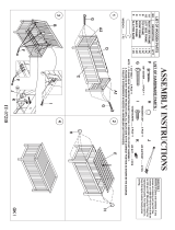
ASSEMBLY
Step 1
1A. Installing The Front Stabilizer – Lift up the front of the Main Frame (15) and align the holes of
the Front Stabilizer (73) with the bracket holes on the Main Frame (15). Ensure that the wheels
are facing outwards. Secure and tighten the Front Stabilizer (73) with two Carriage Bolts (112),
two Locknuts (11) and two Washers (12) using the 13, 17mm Wrench provided.
Tool:
Wrench 13,17mm 1PC
Hardware:
(112) Carriage Bolt
2 PCS
(12) Washer
2 PCS
(11) Lock Nut
2 PCS

12
ASSEMBLY
Step 2
2A. Installing The Rear Stabilizer – Lift the Main Frame (15) up and slide the Rear Stabilizer (1)
into the curved bracket. Align the holes on the Main Frame (15) and the Rear Stabilizer (1). Insert
two Carriage Bolts (13), through the top, and secure with two Washers (12), and two Locknuts
(11). Then on the side, attach two Hexagon Socket Bolts (14), two Curve Washers (60), two
Washers (8), and two Locknuts (7). Tighten the Bolts and Nuts with the Multi-Hex Tool with
Phillips Screwdriver, 13, 17mm Wrench, and 5mm Allen Wrench provided.
.
13,17mm Wrench 1PC
5mm Allen Wrench 1PC
Hardware:
(13) Carriage Bolt
2 PCS
(12) Washer
2 PCS
(11) Locknut
2 PCS
(14) Hexagon Socket
Bolt 2pcs
(8) Washer
2 PCS
(7) Locknut
2 PCS
(60) Curve Washer
2 PCS
Tools:
Multi Hex Tool with Phillips
Screwdriver 1PC

13
ASSEMBLY
Step 3
3A. Installing the Upright Cover & Ring – Slide the Upright Rubber Ring (88) and Upright
Cover (89) onto the Upright Post (35). Hold the parts above the bolt holes for the steps 3b and 3c.
3B. Connecting the Wires – Connect the Upright Wire (75) to the Mainframe Wire (74). After
connecting the wires carefully tuck the wires inside the tubes and slide the Upright Post (35) fully
onto the Main Frame (15).
3C. Installing the Upright Post - Secure the Upright Post (35) to the Main Frame (15) by hand
tightening the eight Hexagon Socket Bolts (6), eight Spring Washers (87), and eight Curve
Washers (60).
WAIT:Fully tighten the bolts in STEP 7 in the following sequence using the 6mm Allen
Wrench provided: A, B, C, D, E, F, G, and H.
6mm Allen Wrench 1PC
Tool:
Hardware:
(6) Hexagon Socket Bolt
8pcs
(87) Spring Washer
8pcs
WARNING:DO NOT FULLY
TIGHTEN THE BOLTS UNTIL
TOLD TO DO SO IN STEP 7.
(60) Curve Washer
8 PCS

14
ASSEMBLY
Step 4
4A. Installing the Left & Right Handlebars – Insert a Bushing (76) and Wave Washer (31) onto
the ends of the smaller tubes sticking out perpendicular to the Upright Post (35). Attach the Right
Handlebar (63R) with one D Washer (114), one Washer (113),one Spring Washer (87) and one
Hexagon Socket Bolt (6). Hand tighten the bolt and repeat this step for the Left Handlebar (63L).
6mm Allen Wrench 1PC
Tool:
Hardware:
(31) Wave Washer
2pcs
(87) Spring Washer
2pcs
(6) Hexagon Socket
Bolt 2pcs
(113) Washer
2pcs
(114) D Washer
2pcs
WARNING:DO NOT FULLY
TIGHTEN THE BOLTS UNTIL
TOLD TO DO SO IN STEP 7.

15
ASSEMBLY
Step 5
5A. Installing the Left Side Lower Handlebar – Ensuring that the lower half curves outwards,
install the Left Lower Handlebar (57L) to the Left Handlebar (63L) with three Hexagon Socket
Bolts (59), three Curve Washers (60), three Lock Nuts (7). Tighten the bolts with the 6mm Allen
Wrench. Make sure that the bolts are inserted as shown in the image.
5B. Installing The Left Pedal Assembly – Place the Wheel (42) on the Aluminum Track Rail (3)
and lift the Crank U Bracket (34) to the Crank (30) and slide the bracket onto the crank. Secure
the bracket with one Hexagon Socket Bolt (6), one Spring Washer (87), one Washer (36), and
one D Washer (115). Tighten the bolt with the 6mm Allen Wrench provided.
5C. Installing The Left Pedal Assembly To The Handlebars – Lift the U Bracket (53) and
connect it to the Left Lower Handlebar (57L) with one Hexagon Socket Bolt (56), one Washer
(12), one Lock Nut (11). Tighten the bolt and nut simultaneously by using the 6mm Allen Wrench
and 13, 17mm Wrench.
Hardware:
6mm Allen Wrench 1PC
13,17mm Wrench 1PC
Tools:
WARNING:DO NOT FULLY
TIGHTEN THE BOLTS UNTIL
TOLD TO DO SO IN STEP 7.
(6) Hexagon
Socket Bolt
1pc
(87) Spring
Washer
1pc
(36) Washer
1pc
(56) Hexagon Socket
Bolt 1pc
(12) Washer
1pc
(11) Lock Nut
1pc
(7) Lock Nut
3pcs
(60) Curve Washer
3pcs
(115) D Washer
1pc
(59) Hexagon
Socket Bolt
3pcs

16
ASSEMBLY
Step 6
6A Installing The Right Side Lower Handlebar – Ensuring that the lower half curves outwards,
install the Right Lower Handlebar (57R) to the Right Handlebar (63R) with three Hexagon
Socket Bolts (59), three Curve Washers (60), three Lock Nuts (7). Tighten the bolts with the
6mm Allen Wrench. Make sure that the bolts are inserted as shown in the image.
6B Installing The Right Pedal Assembly – Place the Wheel (42) on the Aluminum Track Rail (3)
and lift the Crank Bracket (34) to the Crank (30) and slide the bracket onto the crank. Secure the
bracket with one Hexagon Socket Bolt (6), one Spring Washer (87), one Washer (36), and one D
Washer (115). Tighten the bolt with the 6mm Allen Wrench provided.
6C Installing The Right Pedal Assembly To The Handlebars – Lift the U Bracket (53) and
connect it to the Right Lower Handlebar (57R) with one Hexagon Socket Bolt (56), one Washer
(12), one Lock Nut (11). Tighten the bolt and nut simultaneously by using the 6mm Allen Wrench
and 13, 17mm Wrench.
Hardware:
6mm Allen Wrench 1PC
13,17mm Wrench 1PC
Tools:
WARNING:DO NOT FULLY
TIGHTEN THE BOLTS UNTIL
TOLD TO DO SO IN STEP 7.
(6) Hexagon
Socket Bolt
1pc
(87) Spring
Washer
1pc
(36) Washer
1pc
(56) Hexagon Socket
Bolt 1pc
(12) Washer
1pc
(11) Lock Nut
1pc
(7) Lock Nut
3pcs
(60) Curve Washer
3pcs
(115) D Washer
1pc
(59) Hexagon
Socket Bolt
3pcs

17
ASSEMBLY
Step 7
Tightening the Hardware of steps 4, 5, and 6:
To ensure smooth and quiet operation of the elliptical do the following:
1. Turn the Flywheel (66) 3 times to allow the parts of steps 3, 4, 5, and 6 to self-align.
2. Reference the tool images on each step that are needed.
3. First tighten the hardware of the left side first of the machine in the following order according to the
step below:
a. Step 3
b. Step 4A
c. Step 5B
d. Step 5A
e. Step 5C
4. Make sure the Wheel (42) on the Left Pedal Assembly (51L) is NOT tilted too much to the LEFT or
RIGHT.
5. Repeat 1-2 above for the right side of the machine and tighten the hardware as follows:
a.
b. Step 3
c. Step 4A
d. Step 6B
e. Step 6A
f. Step 6C
6. Make sure the Wheel (42) on the Right Pedal Assembly (51R) is NOT tilted too much to the LEFT
or RIGHT.
7. Take the packet of Silicon Oil included and evenly distribute it along both of the Aluminum Track
Rails (3).
8. Turn the flywheel a few times to check for smooth and quiet operation of the elliptical.
9. Go through and double check the Hardware of steps 4, 5, and 6 are thoroughly tightened.

18
ASSEMBLY
Step 8
8A. Installing The Handlebar – As you are slowly attaching the bracket end of the Handlebar (80)
to the Upright Post (35), feed the Pulse Sensor Wires I (111A) through the Upright Post (35) so
that it comes out the top of the post. See Figure AA-2. Secure the Handlebar (80) to the post with
two Hexagon Socket Bolts (6), two Spring Washers (87), and two Curved Washers (60).
Tighten the Screw with the 6mm Allen Wrench.
6mm Allen Wrench 1PC
Tools:
Hardware:
(6) Hexagon Socket
Bolt
2pcs
(60) Curved
Washer
2pcs
(87) Spring Washer
2pcs
/