Page is loading ...

MODELS: C34E-NG11 Natural Gas C34E-LP11 Propane
C34E Classic™ Direct Vent
Freestanding Gas Stove
Owners &
Installation Manual
www.regency-fire.com
C34 Video
- Do not store or use gasoline or other flammable vapors and liquids in the vicinity of this or any other
appliance.
- WHAT TO DO IF YOU SMELL GAS
• Do not try to light any appliance.
• Do not touch any electrical switch: do not use any phone in your building.
Leave the building immediately.
• Immediately call your gas supplier from a neighbour's phone. Follow the gas supplier's
instructions.
• If you cannot reach your gas supplier, call the fire department.
- Installation and service must be performed by a qualified installer, service agency or the gas supplier.
Warning
Fire or Explosion Hazard
failure to follow safety warnings exactly could result in serious
injury, death, or property damage.
Tested by:
920-059a
FPI FIREPLACE PRODUCTS INTERNATIONAL LTD. 6988 Venture St., Delta, BC Canada, V4G 1H4
04.30.20
Installer: Please complete the details on the back cover
and leave this manual with the homeowner.
Homeowner: Please keep these instructions for future reference.
Certified to/Certifié pour: CSA 2.17-2017
ANSI Z21.88-2017
CSA 2.33-2017

2 | Regency
®
CLASSIC™ C34E-11 Direct Vent Freestanding Gas Stove
REGENCY
Classic Direct Vent Freestanding Gas Stove
To the New Owner:
Congratulations! You are the owner of a state-of-the-art Gas Stove by Fireplace Products International Ltd. The Regency
®
Gas Series
of hand crafted appliances has been designed to provide you with all the warmth and charm of a woodstove, at the flick of a switch.
The models C34E-NG11 and C34E-LP11 of this series have been approved by Intertek for both safety and efficiency. As it also bears
our own mark, it promises to provide you with economy, comfort and security for many trouble free years to follow. Please take a mo-
ment now to acquaint yourself with these instructions and the many features of your CLASSIC Direct Vent Freestanding Gas Stove.

Regency
®
CLASSIC™ C34E-11 Direct Vent Freestanding Gas Stove | 3
This Regency
®
Mobile/Manufactured Home listed
appliance comes equipped with a dedicated #8
ground lug to which an 8 gauge copper wire from
the steel chassis ground must be attached.
This Regency
®
Mobile/Manufactured Home Listed
appliance comes factory equipped with a means
to secure the unit.
INFORMATION FOR MOBILE/MANUFACTURED HOMES AFTER FIRST SALE
This Regency
®
product has been tested and listed by Intertek as a Direct Vent Room Heater to the following standards: CAN/CGA-2.17-2017,ANSI Z21.88-
2017 • CSA 2.33-2017.
This Direct Vent System Appliance must be installed in accordance with the manufacturer's installation instructions and the Manufactured Home Construction
and Safety Standard, Title 24 CFR, Part 3280, or the current Standard of Fire Safety Criteria for Manufactured Home Installations, Sites, and Communities
ANSI/NFPA 501A, and with CAN/CSA Z240-MH Mobile Home Standard in Canada.
This appliance installation must comply with the manufacturer's installation instructions and local codes, if any. In the absence of local codes follow the current
National Fuel Gas Code, ANSI Z223.1 and the current National Electrical Code ANSI/NFPA 70 in the U.S.A., and the current CAN/CGA B149 Gas Installation
Code and the current Canadian Electrical Code CSA C22.1 in Canada.
C34 Video
ON DEMAND PILOT LIGHT (SEVEN DAY SAFETY TIMER)
Important information if using the appliance in CPI (continuous pilot mode) only
This appliance is a ProFlame 2 system fitted with the “On Demand” Pilot, a safety feature which will shut down the gas valve completely
by extinguishing the pilot light in the event of a continuous full seven days of inactivity.
This only applies if the CPI (continuous pilot) switch is in the “on” position in your remote control transmitter.
Each time the main burner shuts down, manually or through the call from the thermostat, the seven day timer starts again.
The seven day inactivity timer is controlled within the circuit board. Therefore, if in CPI mode and when the pilot light is extinguished
after seven straight days of inactivity, the CPI setting on the remote control transmitter will remain in the “CPI” (continuous pilot) position.
Therefore, all that is required to relight the pilot would be to press the on/off button on the remote control transmitter from “on” to “off” and
back to “on”. Once the pilot has re-established operation will resume as normal. There is no requirement to do anything with the IPI/CPI
mode on the remote control transmitter.
If the unit never goes as long as seven full days without a call for heat, the pilot will remain lit until it is manually shut-off.
If the unit is being operated in IPI (intermittent pilot) mode, neither the above instructions nor the seven day timer will apply.
See the instructions in this manual and on the Lighting Instructions plate on the appliance to light or re-light the pilot.

4 | Regency
®
CLASSIC™ C34E-11 Direct Vent Freestanding Gas Stove
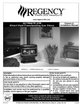
dimensions
28" (711mm)
ALL PICTURES / DIAGRAMS SHOWN THROUGHOUT THIS MANUAL ARE FOR ILLUSTRATION PURPOSES ONLY.
ACTUAL PRODUCT MAY VARY DUE TO PRODUCT ENHANCEMENTS.
UNIT DIMENSIONS

Regency
®
CLASSIC™ C34E-11 Direct Vent Freestanding Gas Stove | 5
table of contents
On Demand Pilot Light (seven day safety timer) ................ 3
Copy of Safety Decal .......................................................... 6
Decal Location .................................................................... 6
For Your Safety ................................................................. 8
Lighting / Shutdown Procedure .......................................... 9
Copy of the Lighting Plate Instructions ............................... 10
Proflame II Remote Control Operating Instructions ............ 11
Warranty ............................................................................ 54
Unit Dimensions ................................................................. 4
MA Code - CO Detector ..................................................... 7
Installation Checklist ........................................................... 15
Locating Your Gas Stove..................................................... 15
Manufactured Mobile Home Additional Requirements ....... 15
Combustion and Ventilation Air ........................................... 15
Clearances to Combustibles ............................................... 15
Wiring Diagram without Thermostat ................................... 16
Optional Wall Thermostat ................................................... 17
Wiring Diagram with Optional Thermostat .......................... 17
Optional Fan Installation - Part #494-917 ........................... 18
Pedestal Assembly ............................................................. 21
Leg ans Bottom Shield Assembly ....................................... 21
Venting Introduction ............................................................ 22
Installation Precautions ...................................................... 22
Safety Precautions for the Installer ..................................... 22
Vent Restrictor Position ...................................................... 22
Exterior Vent Terminal Locations ........................................ 23
4” x 6-5/8” Rigid Pipe Cross Reference Chart only ............. 24
Rigid Pipe Venting Systems ................................................ 26
Venting Arrangements for Horizontal Terminations for All
Venting Systems..................................................................27
Venting Arrangement for Vertical Termination Systems for
Residential Manufactured and Mobile Homes .................... 27
DV Stove Horizontal Vent Kit ............................................. 29
DV Stove Horizontal Vent Kit Installation ............................ 29
Dura-Vent Termination Kit .................................................. 31
owner's information
installer's information
Dura-Vent Horizontal Installations ...................................... 32
Vertical Termination ............................................................ 33
Cathedral Ceilings .............................................................. 34
Converting Class A Metal Chimney to Direct Vent System
(USA Only) ........................................................................ 35
System Data ....................................................................... 36
Glass Connection ............................................................... 36
High Elevation ..................................................................... 36
Gas Pipe Pressure Testing ................................................. 36
885 S.I.T. Valve Description ................................................ 36
Log Installation ................................................................... 37
Door and Glass Frame ....................................................... 37
Door Installation .................................................................. 38
Remote Control Installation ................................................ 39
Optional Wall Thermostat ................................................... 39
Aeration Adjustment ........................................................... 39
Lighting Procedure ............................................................. 40
Shutdown Procedure .......................................................... 40
Copy of the Lighting Plate Instructions ............................... 41
Normal Operating Sounds of Gas Appliances .................... 42
Maintenance Instructions.................................................... 42
Flame Pattern ..................................................................... 42
Glass Gasket ...................................................................... 43
Glass Door .......................................................................... 43
Glass Replacement ............................................................ 43
General Vent Maintenance ................................................. 43
First Fire ............................................................................. 44
Operating Instructions ........................................................ 44
Operation Using an Optional Wall Thermostat ................... 44
Battery Backup ................................................................... 45
Normal Operating Sounds of Gas Appliances .................... 46
Automatic Convection Fan Operation ................................. 46
Adjusting Flame Height ...................................................... 46
Maintenance Instructions.................................................... 46
General Vent Maintenance ................................................. 46
Log Replacement ............................................................... 46
Removing the Valve Assembly ........................................... 47
Removing the Valve Only.................................................... 50
Main Assembly ................................................................... 51
Burner Assembly & Log Set ............................................... 52
Base Options ...................................................................... 53
Warranty ............................................................................ 54

6 | Regency
®
CLASSIC™ C34E-11 Direct Vent Freestanding Gas Stove
safety decal
This is a copy of the label that accompanies
each CLASSIC Direct Vent Freestanding Gas
Stove. We have printed a copy of the contents
here for your review. The safety label is located
on the back panel.
NOTE: Regency
®
units are constantly being
improved. Check the label on the unit and if
there is a difference, the label on the unit is
the correct one.
P
L
5" WC (1.25kpa)
3.5" WC (0.87kpa)
1.6" WC (0.40kpa)
#36 (2.71mm)
21,000 Btu/h (6.15 kw/h)
32,000 Btu/h (9.38 kw/h)
0-4500 ft/pi (0-1372m)
NATURAL GAS STOVE: Model C34E-NG11
L
Minimum supply pressure
Manifold pressure high
Manifold pressure low
Orifice size
Minimum input
Maximum input
Altitude
APPAREIL FONCTIONNANT AU GAZ NATUREL
Modèle C34E-NG11
Pression d'alimentation minimale
Pression lev e manifold é é
Pression manifold basse
Taille de l’orifice
D bit calorifique minimaleé
D bit calorifique maximaleé
Altitude
Model/Modèle :
C34E-NG11
DOOR SEAL:
Please check that the door is properly sealed.
MAY BE INSTALLED IN MANUFACTURED (MOBILE) HOMES AFTER FIRST SALE
DO NOT REMOVE THIS LABEL / NE PAS ENLEVER CETTE ÉTIQUETTE
518
DUPLICATE SERIAL NO.
FPI Fireplace Products International Ltd.
Delta, BC, Canada
Made in Canada/ Fabriqué au Canada
Minimum Clearances to Combustibles /
Dégagements minimaux
par rapport aux matériaux combustibles
A 10"/250mm
B 6"/150mm
E 1.5"/38mm
Minimum ceiling height from
top of unit:36"/914mm
Minimum plafond hauteur en
haut de l'appareil: 36"/914mm
Minimum clearance to vent 1.25“/32mm
Serial No./ No de série
Part #: 920-060
Colour: Black on Grey except selected text is in red as per this print.
Size: Printed at 100% - 10
Material: 2 ml silver matt polyester (DPM SMS)
Feb. 08/19: Created decal
Apr. 29/19: Rev. A - Updated efficiences
Back wall
Side wall
E
A
A
B
Back wall
Side wall
Side wall
This appliance must be installed in accordance with local codes, if any; if none, follow the National Fuel Gas Code, ANSI Z223.1, or Natural Gas and Propane Installation
Code, CSA B149.1.
This appliance must be installed in accordance with the Standard CAN/CSA Z240 MH, Mobile Housing, in Canada, or with the Manufactured Home Construction and Safety
Standard, Title 24 CFR, Part 3280, in the United States, or when such a standard is not applicable, ANSI/NCSBCS A225.1/NFPA 501A, Manufactured Home Installations
Standard or ANSI A119.2 ou NFPA 501C Standard for Recreational Vehicles
This appliance is only for use with the type of gas indicated on the rating plate and may be installed in an aftermarket, permanently located, manufactured (mobile) home where
not prohibited by local codes. See owner's manual for details. Optional Fan Kit (Part # 494-917)
Installer l'appareil selon les codes ou règlements locaux, ou, en l'absence de tels règlements, selon les codes d'installation ANSI Z223.1, National Fuel Gas Code ou CSA-B149.1
en vigueur.
Installer l'appareil selon la norme CAN/CSA-Z240, Série MM, Maison mobiles ou CAN/CSA-Z240 VC, Véhicules de camping, ou la norme 24 CFR Part 3280, Manufactured
Home Construction and Safety Standard. Si ces normes ne sont pas pertinentes, utilisez la norme ANSI/NCSBCS A225.1/NFPA 501A, Manufactured Home Installations
Standard, ou ANSI A119.2 ou NFPA 501C Standard for Recreational Vehicles.
Cet appareil doit être utilisé uniquement avec le type de gaz indiqué sur la plaque signalétique. Cet appareil peut être installé dans une maison préfabriquée ou mobile (É.-U.
seulement) installée à demeure si les règlements locaux le permettent. Voir la notice de l'utilisateur pour plus de renseignements. Cet appareil ne peut pas être utilisé avec
d'autres gaz sauf si une trousse de conversion certifiée est fournie.
This vented gas fireplace heater is not for use with air filters. Ne pas utiliser de filtre à air avec ce foyer au gaz à évacuation.
For use with glass doors certified with the appliance only Pour utilisation uniquement avec les portes vitrées certifiées avec l'appareil
518
VENTED GAS FIREPLACE HEATER - NOT FOR USE WITH SOLID FUELS.
NE PAS UTILISER AVEC DU COMBUSTIBLE SOLIDE. FOYER AU GAZ À ÉVACUATION -
C#4001172
For Use Only with Barrier (Part # 493-005) Follow installation instructions. À utiliser uniquement avec l’écran ( n ° 493-005) Suivre les instructions d'installation.
ELECTRICAL SUPPLY/ALIMENTATION ÉLECTRIQUE:
115V_60HZ less than/moins de 2 AMP
P
L
11" WC (2.74 kpa)
10" WC (2.49 kpa)
6.4" WC (1.59 kpa)
#52 (1.61mm)
23,000 Btu/h (6.74 kw/h)
29,000 Btu/h (8.50 kw/h)
0-4500 ft/pi (0-1372m)
PROPANE GAS STOVE: Model C34E-LP11
L
Minimum supply pressure
Manifold pressure high
Manifold pressure low
Orifice size
Minimum input
Maximum input
Altitude
APPAREIL FONCTIONNANT AU PROPANE
Modèle C34E-LP11
Pression d'alimentation minimale
Pression lev emanifold é é
Pression manifold basse
Taille de l’orifice
D bit calorifique minimaleé
D bit calorifique maximaleé
Altitude
Model/Modèle :
C34E-LP11
Listed: VENTED GAS FIREPLACE HEATER/FOYER AU GAZ À ÉVACUATION
Certified to
/Certifi :
ANSI Z21.88-2017 • CSA 2.33-2017 /
é
CSA 2.17-2017
Refer to Intertek's Directory of Building Products for detailed information.
Pour plus de détails, se reporter au Répertoire des produits de construction de Intertek.
920-060a
CSA P.4.1 Fireplace Efficiency (FE) /Efficacité énergétique des foyers (EEF) CSA P.4.1
Natural Gas / Gaz naturel 64.89%
Propane Gas / Gaz propane 65.82%
CANADIAN ENERGY
PERFORMANCE
VERIFIED
RENDEMENT
ÉNERGÉTIQUE
VÉRIFIÉ
EP5011169
For the State of Massachusetts, installation
and repair must be done by a plumber or
gas fitter licensed in the Commonwealth of
Massachusetts.
For the State of Massachusetts, flexible con-
nectors shall not exceed 36 inches in length.
For the State of Massachusetts, the appli-
ances individual manual shut-off must be a
t-handle type valve.
The State of Massachusetts requires the
installation of a carbon monoxide alarm in
accordance with NFPA 720 and a CO alarm
with battery back up in the same room where
the gas appliance is installed.
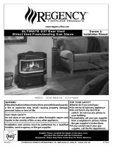
DECAL LOCATION
When locating the rating plate on the C34 the rat-
ing plate will be located at the back of the stove
on the right hand side of the unit. (See Image)
DO NOT REMOVE DECAL FROM UNIT.

Regency
®
CLASSIC™ C34E-11 Direct Vent Freestanding Gas Stove | 7
requirements
installer's information
5.08: Modifications to NFPA-54, Chapter 10
(2) Revise 10.8.3 by adding the following additional requirements:
(a) For all side wall horizontally vented gas fueled equipment installed in every dwelling, building or structure used in whole or in part for
residential purposes, including those owned or operated by the Commonwealth and where the side wall exhaust vent termination is less than
seven (7) feet above finished grade in the area of the venting, including but not limited to decks and porches, the following requirements shall
be satisfied:
1. INSTALLATION OF CARBON MONOXIDE DETECTORS. At the time of installation of the side wall horizontal vented gas fueled
equipment, the installing plumber or gasfitter shall observe that a hard wired carbon monoxide detector with an alarm and battery back-up is
installed on the floor level where the gas equipment is to be installed. In addition, the installing plumber or gasfitter shall observe that a battery
operated or hard wired carbon monoxide detector with an alarm is installed on each additional level of the dwelling, building or structure
served by the side wall horizontal vented gas fueled equipment. It shall be the responsibility of the property owner to secure the services of
qualified licensed professionals for the installation of hard wired carbon monoxide detectors
a. In the event that the side wall horizontally vented gas fueled equipment is installed in a crawl space or an attic, the hard wired carbon
monoxide detector with alarm and battery back-up may be installed on the next adjacent floor level.
b. In the event that the requirements of this subdivision can not be met at the time of completion of installation, the owner shall have a period of
thirty (30) days to comply with the above requirements; provided, however, that during said thirty (30) day period, a battery operated carbon
monoxide detector with an alarm shall be installed.
2. APPROVED CARBON MONOXIDE DETECTORS. Each carbon monoxide detector as required in accordance with the above provisions
shall comply with NFPA 720 and be ANSI/UL 2034 listed and IAS certified.
3. SIGNAGE. A metal or plastic identification plate shall be permanently mounted to the exterior of the building at a minimum height of eight
(8) feet above grade directly in line with the exhaust vent terminal for the horizontally vented gas fueled heating appliance or equipment. The
sign shall read, in print size no less than one-half (1/2) inch in size, "GAS VENT DIRECTLY BELOW. KEEP CLEAR OF ALL
OBSTRUCTIONS".
4. INSPECTION. The state or local gas inspector of the side wall horizontally vented gas fueled equipment shall not approve the installation
unless, upon inspection, the inspector observes carbon monoxide detectors and signage installed in accordance with the provisions of 248 CMR
5.08(2)(a)1 through 4.
(b) EXEMPTIONS: The following equipment is exempt from 248 CMR 5.08(2)(a)1 through 4:
1. The equipment listed in Chapter 10 entitled "Equipment Not Required To Be Vented" in the most current edition of NFPA 54 as adopted by
the Board; and
2. Product Approved side wall horizontally vented gas fueled equipment installed in a room or structure separate from the dwelling, building or
structure used in whole or in part for residential purposes.
(c) MANUFACTURER REQUIREMENTS - GAS EQUIPMENT VENTING SYSTEM PROVIDED. When the manufacturer of Product
Approved side wall horizontally vented gas equipment provides a venting system design or venting system components with the equipment, the
instructions provided by the manufacturer for installation of the equipment and the venting system shall include:
1. Detailed instructions for the installation of the venting system design or the venting system components; and
2. A complete parts list for the venting system design or venting system.
(d) MANUFACTURER REQUIREMENTS - GAS EQUIPMENT VENTING SYSTEM NOT PROVIDED. When the manufacturer of a
Product Approved side wall horizontally vented gas fueled equipment does not provide the parts for venting the flue gases, but identifies
"special venting systems", the following requirements shall be satisfied by the manufacturer:
1. The referenced "special venting system" instructions shall be included with the appliance or equipment installation instructions; and
2. The "special venting systems" shall be Product Approved by the Board, and the instructions for that system shall include a parts list and
detailed installation instructions.
(e) A copy of all installation instructions for all Product Approved side wall horizontally vented gas fueled equipment, all venting instructions,
all parts lists for venting instructions, and/or all venting design instructions shall remain with the appliance or equipment at the completion of
the installation.
MA Code - CO Detector
(for the State of Massachusetts only)

8 | Regency
®
CLASSIC™ C34E-11 Direct Vent Freestanding Gas Stove
owner's information
CLOTHING OR OTHER FLAMMABLE
MATERIAL SHOULD NOT BE PLACED
ON OR NEAR THE APPLIANCE.
CHILDREN AND ADULTS SHOULD BE
ALERTED TO THE HAZARDS OF HIGH
SURFACE TEMPERATURES, ESPE-
CIALLY THE FIREPLACE GLASS, AND
SHOULD STAY AWAY TO AVOID BURNS
OR CLOTHING IGNITION.
INSTALLATION AND REPAIR SHOULD
BE DONE BY AN AUTHORIZED
SERVICE PERSON. THE APPLIANCE
SHOULD BE INSPECTED BEFORE
USE AND AT LEAST ANNUALLY BY A
PROFESSIONAL SERVICE PERSON.
MORE FREQUENT CLEANING MAY
BE REQUIRED DUE TO EXCESSIVE
LINT FROM CARPETING, BEDDING
MATERIAL, ETC. IT IS IMPERATIVE THAT
CONTROL COMPARTMENTS, BURNERS
AND CIRCULATING AIR PASSAGEWAYS
OF THE APPLIANCE BE KEPT CLEAN.
DUE TO HIGH TEMPERATURES, THE
APPLIANCE SHOULD BE LOCATED
OUT OF TRAFFIC AND AWAY FROM
FURNITURE AND DRAPERIES.
WARNING: FAILURE TO INSTALL THIS
APPLIANCE CORRECTLY WILL VOID
YOUR WARRANTY AND MAY CAUSE A
SERIOUS HOUSE FIRE.
YOUNG CHILDREN SHOULD BE CARE-
FULLY SUPERVISED WHEN THEY ARE
IN THE SAME AREA AS THE APPLI-
ANCE. TODDLERS, YOUNG CHILDREN
AND OTHERS MAY BE SUSCEPTIBLE
TO ACCIDENTAL CONTACT BURNS. A
PHYSICAL BARRIERS IS RECOMMEND-
ED IF THERE ARE AT RISK INDIVIDUAL
IN THE HOUSE. TO RESTRICT ACCESS
TO A FIREPLACE OR STOVE, INSTALL
AN ADJUSTABLE SAFETY GATE TO
KEEP TODDLERS, YOUNG CHILDREN
AND OTHER AT RISK INDIVIDUALS OUT
OF THE ROOM AND AWAY FROM HOT
SURFACES.
FOR YOUR SAFETY
This appliance requires air for proper combustion.
Always provide adequate combustion and
ventilation air. Follow instructions and information
in CSA B149.1 (in Canada) or the National Fuel Gas
Code ANS Z223.1/NFPA (in the USA), regarding
requirements for combustion and ventilation air.
ANY SAFETY SCREEN, GUARD, OR
BARRIER REMOVED FOR SERVICING
THE APPLIANCE, MUST BE REPLACED
PRIOR T O OPERATING THE APPLIANCE.
IF THE BARRIER BECOMES DAMAGED,
THE BARRIER SHALL BE REPLACED
WITH THE MANUFACTURER'S BARRIER
FOR THIS APPLIANCE.
A BARRIER DESIGNED TO REDUCE
THE RISK OF BURNS FROM THE HOT
VIEWING GLASS IS PROVIDED WITH
THIS APPLIANCE AND SHALL BE
INSTALLED FOR THE PROTECTION
OF CHILDREN AND OTHER AT-RISK
INDIVIDUALS
Part # - 919-874
Description: Prop. 65 Short form label
Date: May 30/18
Colour: Black font on white
Size: 5"W x 0.7"H
919-874
!
WARNING: Cancer and Reproductive Harm
www.P65Warnings.ca.gov

Regency
®
CLASSIC™ C34E-11 Direct Vent Freestanding Gas Stove | 9
owner's information
* Not offered on all models.
IMPORTANT: The remote control system supplied with this appliance has
several options for starting/operating the appliance using the battery holder
and ON/OFF key on the hand held transmitter.
Prior to operating this appliance, please read the remote control operating
instructions (packaged with remote control) to understand how to operate
this remote control system.
1. Ensure the battery holder switch is in the Remote position and / or wall
mounted battery holder (if equipped) is in the <REMOTE> position.
2. Press and release the ON/OFF button on the remote handheld transmitter
(see Diagram 1). An audible beep should be heard from the receiver. If
not using the remote, the unit can also be turned on by sliding the battery
holder switch to the <ON> position (if equipped).
Note: The first try for ignition will last approximately 60 seconds. If there is no
flame ignition (rectification) the board will stop sparking for approximately
35 seconds. After wait time , the board will start second try for ignition by
sparking for approximately 60 seconds . If there is still no positive ignition
the board will go into lock out.
The system will need to be reset as follows:
a) Turn the system off by pressing the ON/OFF button on the remote.
b) Wait 5 minutes then repeat from step 2.
SHUTDOWN PROCEDURE
1. Press the ON/OFF button on the remote
2. If service is to be performed- you must disconnect power and shut off gas
to the unit.
ON/OFF
Button
Diagram 1
Remote shown in Manual Mode on Hi
3. After approximately 4 seconds the spark ignition system will spark for 60
seconds to light the main burner.
4. The unit will turn on.
LIGHTING PROCEDURE
Continuous Pilot/Intermittent Pilot (CPI/IPI) selection
See remote control instructions for details.
*
*
*
*
On Demand Pilot (seven day safety timer)
Important information if using the appliance in CPI (continuous pilot mode) only
This appliance is a ProFlame 2 system fitted with the “On Demand” Pilot, a safety feature which will shut down the gas valve completely by extinguishing the
pilot light in the event of a continuous full seven days of inactivity.
This only applies if the CPI (continuous pilot) switch is in the “on” position in your remote control transmitter.
Each time the main burner shuts down, manually or through the call from the thermostat, the seven day timer starts again.
The seven day inactivity timer is controlled within the circuit board. Therefore, if in CPI mode and when the pilot light is extinguished after seven straight days
of inactivity, the CPI setting on the remote control transmitter will remain in the “CPI” (continuous pilot) position. Therefore, all that is required to relight the pilot
would be to press the on/off button on the remote control transmitter from “on” to “off” and back to “on”. Once the pilot has re-established operation will resume
as normal. There is no requirement to do anything with the IPI/CPI mode on the remote control transmitter.
If the unit never goes as long as seven full days without a call for heat, the pilot will remain lit until it is manually shut-off.
If the unit is being operated in IPI (intermittent pilot) mode, neither the above instructions nor the seven day timer will apply.
See the instructions in this manual and on the Lighting Instructions plate on the appliance to light or re-light the pilot.

10 | Regency
®
CLASSIC™ C34E-11 Direct Vent Freestanding Gas Stove
owner's information
COPY OF THE LIGHTING PLATE INSTRUCTIONS
919-634
Part #: 919-634
Colours: Black on Grey, except
for parts indicated as being
Red.
Size: 100%
w- 5.19"
h- 10.4"
Feb 09/16: Created decal
A) This appliance is equipped with an ignition device which automatically lights the pilot.
Do not try to light the pilot by hand.
B) BEFORE OPERATING
smell all around the appliance area for gas. Be sure to smell next to the oor
because some gas is heavier than air and will settle on the oor
.
WHAT TO DO IF YOU SMELL GAS
-
Do not try to light any appliance.
-
Do not touch any electric switch, do not use any phone in your building.
-
Immediately call your gas supplier from a neighbours phone. Follow the gas supplier’s instructions.
-
If you cannot reach your gas supplier, call the re department.
C) Do not use this appliance if any part has been under water. Immediately call a qualied service
technician to inspect the appliance and replace any part of the control system and any
gas control which has been underwater.
A) Cet appareil est muni d’un dispositif d’allumage qui allume automatiquement la veilleuse.
Ne tentez pas d’allumer la veilleuse manuellement.
B) AVANT LA MISE EN MARCHE
, reniez tout autour de l’appareil pour déceler une odeur de gaz. Reniez au niveau
du plancher, car certains gaz sont plus lourds que l’air et peuvent s’accumuler au niveau du sol.
QUE FAIRE SI VOUS SENTEZ UNE ODEUR DE GAZ :
• Ne tentez pas d’allumer l’appareil
• Ne touchez à aucun interrupteur; n'utilisez pas de téléphones se trouvant dans le bâtiment.
• Appelez immédiatement votre fournisseur de gaz depuis un téléphone extérieur. Suivez les
instructions du fournisseur.
• Si vous ne pouvez pas rejoindre le fournisseur, appelez le service incendie.
C) N’utilisez pas cet appareil s’il a été plongé dans l’eau, même partiellement. Faites inspecter l’appareil par un tech
-
nicien qualié et remplacez tout élément du système de contrôle ou de commande qui a été plongé dans l’eau.
DO NOT REMOVE THIS INSTRUCTION PLATE
TO TURN OFF GAS APPLIANCE
This appliance must be installed in accordance with local codes, if any;
if none, follow the National Fuel Gas Code, ANSI Z223.1/NFPA 54, or
Natural Gas and Propane Installation Codes, CSA B149.1.
CAUTION: Hot while in operation. Do not touch. Severe Burns may result. Due to high surface
temperatures keep children, clothing and furniture, gasoline and other liquids having ammable
vapors away. Keep burner and control compartment clean. See installation and operating
instructions accompanying appliance.
WARNING: If you do not follow these instructions exactly, a fire or explosion may result
causing property damage, personal injury or loss of life. Improper installation, adjustment,
alteration, service or maintenance can cause injury or property damage. Refer to the owner’s
information manual provided with this appliance. For assistance or additional information
consult a qualified installer, service agency or gas supplier.
AVERTISSEMENT. Quiconque ne respecte pas scrupuleusement les instructions de la présente
notice risque de déclencher un incendie ou une explosion pouvant entraîner des dégâts matériels
ou des blessures pouvant être mortelles.
Tout défaut d'installation, d'ajustement, de modication, de service ou d'entretien peut entraîner
des blessures ou des dommages matériels. Reportez-vous au manuel d'utilisation fourni avec
cet équipement. Pour obtenir de l'aide ou des informations complémentaires, consulter un
installateur ou un service d'entretien qualié, ou le fournisseur de gaz.
1) Ensure the Main switch is in the ON position and/or the wall mounted battery holder (if equipped) is in the
<REMOTE> position.
2) Press and release the ON/OFF button on the remote handheld transmitter. An audible beep should be
heard from the receiver. If not using the remote, the unit can also be turned on by sliding the battery
holder switch to the <ON> position (if equipped).
3) After approximately 4 seconds the spark ignition system will spark for 60 seconds to light the main burner.
4) The unit will turn on.
Note: The rst attempt to ignition will last approximately 60 seconds. If there is no ame ignition (rectica
-
tion) the board will stop sparking for approximately 35 seconds. After this wait time, the board will start a
second try for ignition by sparking for approximately 60 seconds. If there is still no positive ignition after the
second attempt the board will go into lock out.
The system will need to be reset as follows (after going into lock out mode):
a) Wait 5 minutes - turn the system o by pressing the ON/OFF button on the remote.
b) After approximately 2 seconds press the ON/OFF button again.
c) Unit will repeat step 2.
1) S’assurer que le commutateur principal est en position ON et/ou que le bloc-piles mural (le cas échéant)
est en position <REMOTE>.
2) Appuyer sur la touche ON/OFF de la télécommande et relâcher. Un bip sonore retentira depuis le récep
-
teur. Si vous n'utilisez pas la télécommande, l'appareil peut également être allumé en faisant glisser le com
-
mutateur du bloc-piles à la position <ON> (le cas échéant).
3) Après environ 4 secondes, le système d'allumage produira une étincelle pendant 60 secondes pour al
-
lumer le brûleur principal.
4) L'appareil s’allumera.
Remarque : Au premier allumage, le système tente d’allumer les ammes pendant 60 secondes. Si l’essai
est infructueux, le système fera une pause de 35 secondes. C’est ce qu'on appelle l'étape de rectication.
Ce délai écoulé, le système tente à nouveau d'allumer les ammes en produisant des étincelles pendant 60
secondes. Si les ammes ne s’allument toujours pas, le système se met en mode verrouillage.
Il faut alors le réinitialiser en suivant les étapes ci-dessous (pour le déverrouiller) :
a) Attendre 5 minutes et éteindre l’appareil en appuyant sur la touche ON/OFF de la télécom-
mande.
b) Attendre 2 secondes et appuyer encore une fois sur la touche ON/OFF.
c) L'unité répétera l'étape 2.
1)
Press the ON/OFF button on the remote.
2)
If service is to be performed–you must disconnect power and shut off gas to the unit.
1)
Appuyer sur la touche ON/OFF de la télécommande.
2)
En cas d'entretien, vous devez débrancher l'alimentation et couper le gaz alimentant l'unité.
LIGHTING INSTRUCTIONS
FOR YOUR SAFETY READ BEFORE LIGHTING

Regency
®
CLASSIC™ C34E-11 Direct Vent Freestanding Gas Stove | 11
owner's information
PROFLAME II REMOTE CONTROL OPERATING INSTRUCTIONS
919-829
09.29.17
PROFLAME II REMOTE CONTROL OPERATING INSTRUCTIONS
WARNING: THE TRANSMITTER AND RECEIVER ARE RA‑
DIO FREQUENCY DEVICES. PLACING THE RECEIVER IN
OR NEAR METAL MAY SERVERELY REDUCE THE SIGNAL
The Proflame 2 Transmitter provides for controlling the following hearth
appliance functions:
1. Main Burner On/Off
2. Main Burner flame modulation (6 levels)
3. Choice of standing or intermittent pilot (CPI/IPI)
4. Thermostat and Smart thermostat functions
5. Accent light modulation (6 levels)**
6. Split flow valve**
7. Comfort Fan speed modulation (6 levels)**
** This feature is not available on all models.
IMPORTANT:The Proflame Transmitter 2 is an integrated part of the
Proflame 2 System, which consists of these elements:
• Proflame 2 Transmitter, to be used in conjunction with:
• Integrated Fireplaces Control (Proflame 2 IFC)
The Proflame Transmitter uses a streamline design with a simple button
layout and informative LCD display (Fig. 1). A Mode Key is provided to
index between the features and a Thermostat Key is used to turn on/off
or index through Thermostat functions (Fig. 1 & 2). Additionally, a Key
Lock feature is provided (Fig. 22).
Figure 1: Proflame Transmitter
Figure 2: Transmitter LCD Display
TECHNICAL DATA
REMOTE CONTROL
Supply Voltage 4.5V (three 1.5V AAA batteries)
Ambient temperature
ratings
0 - 50
o
C (32 - 122
o
F)
Radio Frequency 315 MHZ
ATTENTION!
- Turn “OFF” the main gas supply of the appliance during installation or
maintenance of the Receiver device.
- Turn “OFF” main gas supply to the appliance prior to removing or rein-
serting the batteries.
- In case of remote control malfunction, turn off the IFC device using the
"ON/OFF" main switch.
- For installation / maintenance, switch off the IFC device removing main
power supply plug.
OPERATING PROCEDURE
Initializing the System for the first time
Power the receiver. Activate the procedure of the receiver address pro-
gramming, see the receiver instruction (*). The Receiver will “beep” three
(3) times to indicate that it is ready to synchronize with a Transmitter. Install
the 3 AAA type batteries in the Transmitter battery bay, located on the
base of the Transmitter. (fig. 3) With the batteries already installed in the
Transmitter, push the On button. The Receiver will “beep” four times to
indicate the Transmitter’s command is accepted and sets to the particular
code of that Transmitter. The system is now initialized.
(*) The receiver may be independent or integral to the IFC hearth ap-
pliance control module. The receiver instruction may not be indepen-
dent when part of the IFC.
Figure 3: Battery Compartment
4
PROFLAM
E 2
TRANSMI
TTER
USE
ANDINST
AL
L
The Proflame Remote Control System consists of three elements:
1. Proflame Transmitter.
2. Proflame Receiver and a wiring harness to connect the Receiver to the gas valve, stepper
motor and Fan Control Module.
3. Proflame Fan Control Module (FCM)
The Proflame Transmitter uses a streamline design with a simple button layout and informative
LCD display (Fig. 1).
The Transmitter is powered by 3 AAA type batteries.
A Mode Key is provided to Index between the features and a Thermostat Key is used to turn on/
off or index through Thermostat functions (Fig. 1 & 2).
TRANSMITTER (Remote Control with LCD Display)
SYSTEM DESCRIPTION
Fig. 1: PROFLAME Transmitter.
Low battery alarm
Child safety lock-out
Room
Temperature
Aux ON
Set Point
Temperature/Level/State
Flame ON
Thermostat OFF/
ON/SMART
Fan
Fig. 2: Transmitter LCD display.
Transmission
Turn on the Appliance
With the system OFF, press the ON/OFF Key on the
Transmitter. The Transmitter display will show some other
active Icons on the screen. At the same time the Receiver
wil activate the appliance. A single “beep” from the
Receiver will confirm reception of the command.
Turn off the Appliance
With the system ON, press the ON/OFF Key on the
Transmitter. The Transmitter LCD display will only show
the room temperature (Fig. 6). At the same time the
Receiver will turn off the appliance. A single “beep” from
the Receiver confirms reception of the command.
Fig. 6: Remote Control display.
3 Positions Slider
Fig. 4: Proflame Receiver body.
PRG Key
Fig3: Battery
compartment.
Fig. 4: Remote Control display in Farenheit. Fig. 5: Remote Control display in Celsius.
9957099_00_nero_mod_05-10-2011.i4 4 05/10/2011 8.36.38
1

12 | Regency
®
CLASSIC™ C34E-11 Direct Vent Freestanding Gas Stove
owner's information
919-829 09.29.17
Figure 4: Remote Control dis-
play in Farenheit.
Temperature indication Display
With the system in the "OFF" position, press the Thermostat Key and
the Mode Key at the same time. Look at the LCD screen on the transmit-
ter to verify that a C or F is visible to the right of the room temperature
display (Figures 4 & 5).
Figure 5: Remote Control dis-
play in Celsius.
Turn on the Appliance
With the system OFF, press the ON/
OFF Key on the Transmitter. The
Transmitter display will show some
other active Icons on the screen. At
the same time the Receiver wil ac-
tivate the appliance. A single “beep”
from the Receiver will confi rm recep-
tion of the command.
Figure 6: Remote Control
display
Remote-Flame Control
The profl ame has six (6) fl ame levels. With the system on, and the fl ame
level at the maximum in the appliance, pressing the Down Arrow Key
once will reduce the fl ame height by one step until the fl ame is turned off.
The Up Arrow Key will increase the fl ame height each time it is pressed.
If the Up Arrow Key is pressed while the system is on but the fl ame is off,
the fl ame will come on in the high position. ( Fig. 7 & 8 ) A single “beep”
will confi rm reception of the command.
Fig. 7
Fig. 8
Room Thermostat (Transmitter Operation)
The Remote Control can operate as a room thermostat. The thermostat
can be set to a desired temperature to control the comfort level in a room.
To activate this function, press the Thermostat Key (Fig. 1). The Lcd
display on the Tr ansmitter will change to show that the room thermostat
is “ON” and the set temperature is now displayed (Fig. 9). To adjust the
set temperature, press the Up or Down Arrow Keys until the desired set
temperature is displayed on the LCD screen of the Tr ansmitter.
Figure 9 Figure 10
Turn off the Appliance
With the system ON, press the ON/OFF Key on the Transmitter. The
Transmitter LCD display will only show the room temperature (Fig. 6).
At the same time the Receiver will turn off the appliance. A single “beep”
from the Receiver confi rms reception of the command.
2

Regency
®
CLASSIC™ C34E-11 Direct Vent Freestanding Gas Stove | 13
owner's information
919-829
09.29.17
Smart Thermostat (Transmitter Operation)
The Smart Thermostat function adjusts the fl ame height in accordance
to the difference
between the set point temperature and the actual room temperatures.
As the room
temperature gets closer to the set point the Smart Function will modulate
the fl ame down.
To activate this function, press the Thermostat Key (Fig. 1) until the word
"SMART" appears to
the right of the temperature bulb graphic (Fig. 11).
To adjust the set temperature, press the Up or Down Arrow Keys until
the desidered set
temperature is displayed on the LCD screen of the Transmitter (Fig. 12).
Note. When Smart Thermostat is activated, manual fl ame height adjust-
ment is disabled.
Figure 12Figure 11: Smart Flame Function
Fan Speed Control**
If the appliance is equipped with a hot air circulating fan, the speed of
the fan can be controlled by the Profl ame system. The fan speed can be
adjusted through six (6) speeds. To activate this function use the Mode Key
(fi g.1) to index to the fan control icon (Fig. 13). Use the Up/Down Arrow
Keys (fi g.1) to turn on, off or adjust the fan speed (fi g. 14). A single “beep”
will confi rm reception of the command.
Figure 13 Figure 14
Remote dimmer control (Light)**
The auxiliary function controls the AUX power outlet by the dimmable
light control. To activate this function use the Mode Key (fi g. 1) to index
to the AUX icon (fi g. 15 & 16).
The intensity of the output can be adjusted through six (6) levels. Use
the Up/Down Arrow Keys (fi g.1) adjust the output level (fi g. 16). A single
“beep” will confi rm reception of the command.
Note: This function is available only with the IFC Control Module.
Figure 15 Figure 16
Split Flow control**
The secondary burner is controlled by the split Flow. To activate this
function use the Mode Key (fi g. 1) to index to the SPLIT FLOW mode
icon (fi g. 17 & 18).
Pressing the Up Arrow Key will activate the secondary burner. Pressing
the Down Arrow Key will turn the secondary burner off. A single “beep”
will confi rm the reception of the command.
Figure 17 Figure 18
3

14 | Regency
®
CLASSIC™ C34E-11 Direct Vent Freestanding Gas Stove
owner's information
919-829 09.29.17
Continuous Pilot/Intermittent Pilot (CPI/IPI) selection
Note: Power vent models do not have a Continuous
Pilot option.
With the system in "OFF" position press the Mode Key (fi g. 1) to index
to the CPI mode icon (fi g. 19 & 20).
Pressing the Up Arrow Key will activate the Continuous Pilot Ignition
mode (CPI). Pressing the Down Arrow Key will return to IPI. A single
“beep” will confi rm the reception of the command.
Figure 19 Figure 20
KEY LOCK
This function will lock the keys to avoid unsupervised operation.
To activate this function, press the MODE and UP Keys at the same
time (fi g. 21).
To de-activate this function, press the MODE and UP Keys at the
same time.
Figure 21
LOW BATTERY POWER DETECTION
Transmitter
The life span of the remote control batteries depends on various factors:
quality of the batteries used, the number of ignitions of the appliance,
the number of changes to the room thermostat set point, etc.
When the Tr ansmitter batteries are low, a Battery Icon will appear on the
LCD display of the Transmitter (Fig. 22) before all battery power is lost.
When the batteries are replaced this Icon will disappear.
Figure 22
CPI/IPI SWITCH
This appliances comes equipped with a CPI/IPI switch. The function of
both the CPI/IPI switch are as follows:
Continuous pilot (CPI) - A pilot that when in operation, is intended to
remain continuously ignited until it is manually interrupted.
Intermittent pilot (IPI) - A pilot that is automatically ignited when an ap-
pliance is called on to operate and which remains continuously ignited
during each period of main burner operation. The pilot is automatically
extinguished when each main burner operating cycle is completed. The
mode of the fi replace is easily changed from an intermittent pilot ignition
system (IPI) to a continuous pilot ignition system (CPI) by using remote
control as noted above.
The benefi ts of having as CPI are as follows:
- Keeps venting primed for trouble free start-up under colder weather
conditions or inversions.
- Keeps the unit glass warm, which decreases the amount of condensa-
tion on start-up
-Provides owners with fl exibility to choose a traditional continuous pilot.
The primary benefi t of having the IPI function is a signifi cant savings on
fuel as the pilot will only run when there is a call for heat.
Thermostat Icon: If the thermostat icon is not present on the remote
transmitter, follow instructions noted below
1. Take one or all batteries out (removing one battery will work).
2. Press and hold down the Thermostat button on the remote.
3. Reinstall the 3rd battery while still holding thermostat button down.
4. If you see "Set" the thermostat option is now enabled. If you see "Clr"
the thermostat option is now disabled
5. Repeat the procedure if you did not see the "Set" or "Clr" to remove
or add the option back to the remote.
Enable all other functions if not present on the remote transmitter, follow
instructions noted below:
1. Remove one battery or all batteries (removing one battery will work).
2. Press and hold both the ON/OFF and the MODE button at the same time .
3. Reinstall the 3rd battery while still holding both buttons (keep holding
buttons once 3rd battery is installed, then release the mode button only.
4. The screen will show either "Clr" or "Set" with the 1st mode being
your option to disable or enable.
5. "Clr" will remove the mode by using the up or down arrow while still
holding both buttons (icon will disappear once removed, or icon
will
show up again once added).
6. Use the "Mode" button to move to the next function.
7. "Set" will add that mode by using the up or down arrow while still
holding both buttons (icon will disappear once removed, or icon
will show up again once added) Use the "Mode" button to move
to the next function.
Note: You should never program out the fan (if installed) or CPI/IPI
mode on the remote.
4

Regency
®
CLASSIC™ C34E-11 Direct Vent Freestanding Gas Stove | 15
installation
AA
B
Back wall
Back wall
Side wall
Side wall
Side wall
C
D
F
F
E
E
COMBUSTION AND
VENTILATION AIR
The combustion air from this appliance is drawn
from outside the building through the outer flue. Ex-
tra provision for combustion air is not required.
CLEARANCES TO
COMBUSTIBLES
The clearances listed below are MINIMUM
distances. Measure the clearance to both the
appliance and the chimney connector. The
farthest distance is correct if the two clearances
do not coincide. For example, if the appliance
is set as indicated in one of the Diagrams but
the back is too close, move the stove until the
correct clearance to the back is obtained.
This unit can be installed on a solid combustible
surface like a wood floor. This unit can also be
installed directly on carpeting or vinyl when the
bottom pedestal cover plate (provided with the
unit) is installed.
This appliance may be installed only with the
clearances as shown in the situations pictured.
Do not combine clearances from one type of
installation with another in order to achieve
closer clearances.
Use the minimum clearances shown in the
Diagrams below:
INSTALLATION
CHECKLIST
1. Locate your appliance. Refer to the following
sections:
a. Locating Your Classic Gas Stove
b. Clearances to Combustibles
c. Venting. See "Exterior Vent Terminal
Locations" to " Venting Arrangements"
sections.
2. Install Optional Fan. Refer to "Optional Fan
Installation" section.
3. Assemble stove base - pedestal or bottom shield
and legs. Refer to "Pedestal Assembly" or "Leg
and Bottom Shield Assembly" sections.
4. Choose a venting option and Install accordingly.
Refer to the following sections where applicable:
a. DV Stove Horizontal Vent Kit
b. Dura-Vent Termination kits
c. Vent Restrictor setting
d. Converting CLass-A Metal Chimney to Direct
Vent System.
5. Make gas and electrical connections. Refer to
"Gas Connection" section. Test the pilot. Must
be as per Diagram in "Pilot Adjustment" section.
6. Install 4-AA batteries into battery box. This will
enable operation of appliance manually when
in "ON" position.
7. Test gas pressure. Refer to "Gas Pipe Pressure
Testing" section.
8. Install standard and optional features. Refer to
the following sections where applicable:
a. Log Installation
b. Door and Glass Frame
c. Door Handle
d. Safety Screen
e. Remote Control
f. Wall Thermostat
g. Pedestal and/or bottom heat shield and legs
h. Fan assembly
9. Final check. Refer to "Final Check" section.
Before leaving this unit with the customer, the
installer must ensure that the appliance is fir-
ing correctly and operation fully explained to
customer.
This includes:
1. Clocking the appliance to ensure the correct
firing rate (rate noted on label) after burning
appliance for 15 minutes.
2. If required, adjusting the primary air to ensure
that the flame does not carbon. First allow
the unit to burn for 15-20 min. to stabilize.
3. Check for proper draft.
CAUTION: Any alteration to the product that
causes sooting or carboning that results in dam-
age is not the responsibility of the manufacturer.
LOCATING YOUR
GAS STOVE
When selecting a location for your stove, ensure
that the clearances on this page are met as well
as ensuring that there is adequate accessibility
for servicing and proper operation.
For Vent Termination requirements, see "Exterior
Vent Terminal Locations" section.
MANUFACTURED MOBILE HOME
ADDITIONAL REQUIREMENTS
1. Ensure that structural members are not cut
or weakened during installation.
2. Ensure proper grounding using the #8 ground
lug provided. See "Optional Fan Installation"
section.
3. Appliance must be anchored to the floor. See
"Pedestal Assembly" & "Leg and Bottom"
sections.
A) Cross Corner
B) Room Divider
C) Island
D) Flat on Wall
E) Flat on Wall Corner
F) Flush with Wall/Alcove
C34 Clearance to Combustibles
A Side Wall to Unit 10" / 250 mm
B Back Wall to Unit 6" / 150 mm
E Side Wall to Unit 1.5" / 38 mm
C34 Reference Dimensions
C Back Wall to Flue Centerline 13" / 330 mm
D Side Wall to Flue Centerline 22" / 559 mm
F Side Wall to Flue Centerline 14" / 356 mm
Minimum ceiling height is 36" / 914 mm from
top of unit.
Minimum clearance to vent 1-1/4" (32mm).

16 | Regency
®
CLASSIC™ C34E-11 Direct Vent Freestanding Gas Stove
installation
This heater does not require a 120V A.C. supply for
operation. In case of a power failure, the remote
control/thermostat will continue to operate.
CAUTION: Ensure that the wires
do not touch a hot surface and are
away from sharp edges.
WARNING:
Electrical Grounding
Instructions
This appliance is equipped with
a three pronged (grounding)
plug for your protection against
shock hazard and should be
plugged directly into a properly
grounded three-prong recep-
tacle. Do not cut or remove the
grounding prong from this plug.
Note:
4 AA Batteries must be installed into the back
up battery compartment however for this unit to
operate when power is lost. See battery back
up instructions in this manual The fan will not
operate during a power outage.
WIRING DIAGRAM WITHOUT THERMOSTAT
EXTERNAL ANTENNA

Regency
®
CLASSIC™ C34E-11 Direct Vent Freestanding Gas Stove | 17
installation
OPTIONAL WALL THERMOSTAT
A wall thermostat may be installed if desired.
Connect the wires as per the wiring diagrams.
Note: Preferable if the thermostat is installed
on an interior wall.
Regency
®
offers an optional programmable
thermostat but any 250-750 millivolt rated non-
anticipator type thermostat that is CSA, ULC or
UL approved may be used.
CAUTION
Do not connect the millivolt
wall thermostat wires
to the 120V wires.
WIRING DIAGRAM WITH OPTIONAL THERMOSTAT
GREY
GREY
Thermostat( Optional)
(Millivolt)
EXTERNAL ANTENNA

18 | Regency
®
CLASSIC™ C34E-11 Direct Vent Freestanding Gas Stove
installation
OPTIONAL FAN INSTALLATION - PART # 494-917
C34E-11
03.04.19920-073
Front of Unit
Back of Unit
Bottom
of Unit
Diagram 4 - Pedestal version shown
8. Locate the red/black wires at the IFC (Intermittent Fireplace Control)
located at the left hand side of the gas valve. Remove the plastic caps
on the red/black wires and discard. See Diagram 6.
1. Open pedestal door and remove door cover plate by removing 4 screws.
See Diagram 3 (pedestal model only).
2. Remove valve cover plate by removing 2 screws.
3. Remove wire from back side of battery holder/receiver.
4. Screw the 4 screws provided into the nutserts as shown in Diagram 4. Do
not tighten screws.
5. Place the fan assembly partially in door cover plate hole (pedestal model
only).
OPTIONAL FAN INSTALLATION - PART # 494-917
Diagram 3
Diagram 1
Remove 7 screws on top
Loosen 4 screws on bottom–
slide access panel to the
right to remove
Diagram 2
Loosen 6 screws–slide access
panel to the front of unit to
remove
Leg unit: Loosen 6 screws on bottom access panel–slide panel toward the
front to remove.
IMPORTANT Disconnect power supply
before installing / servicing blower
Pedestal unit: To install the fan in an installed stove-access from front through
the pedestal by following the directions below. If the stove is not
installed - access through the back - open back as shown below.
6. Lift the fan assembly in through the pedestal or bottom heat shield
and up through the cut out as shown in Diagrams 4 and 5.
7. Line up the keyhole slots with the matching screws and pull back
slightly to lock into place. While holding fan assembly in place, tighten
screws to secure fan assembly.
Diagram 5
WARNING: Electrical Grounding Instructions
This appliance is equipped with a three pronged (grounding) plug for your
protection against shock hazard and should be plugged directly into a
properly grounded receptacle.
Plastic
Caps
Diagram 6

Regency
®
CLASSIC™ C34E-11 Direct Vent Freestanding Gas Stove | 19
installation
C34E-11
03.04.19
920-073
9. Once the plastic caps have been removed, connect the fan wires
(white and black) to the power supply wires. Connect red-white and
black-black. See Diagram 7.
Tu ck any loose wires neatly into plastic clip located on the underside
of the fan.
11. Once the ground wire has been attached to the blower, route the
ground wire back to the IFC board and attach to Ground Lug located
on the left front of the unit. See Diagram 9.
Diagram 7
Diagram 9
Diagram 10
10. After the wires have been connected attach the ground wire to the left
side of the blower (Diagram 8).
12. Route the power cord through the rear of the unit and attach the strain
relief to the back of unit as shown in Diagram 10 (bottom heat shield
shown).

20 | Regency
®
CLASSIC™ C34E-11 Direct Vent Freestanding Gas Stove
installation
C34E-11
03.04.19920-073
13. Once the blower has been completely installed connect the receiver
to the wire harness and re assemble Valve cover plate by re installing
the 2 Philip head screws.
14. Next reinstall the door cover plate by re-installing 4 Philip head screws
(pedestal model). On the bottom heat shield, reattach the bottom
access panel into the 6 keyhole slots and tighten 6 screws.
/