Page is loading ...

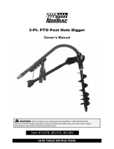
Post Hole Diggers
• Compact • Standard • Heavy Duty
is safety alert symbol identies important safety messages in
this manual. Failure to follow this important safety information
may result in serious injury or death.
MODEL 90 / MODEL 100 / MODEL 110
# 100623 # 100498 # 100624
Operation Manual
!
Part # 100625 Rev D

1100 W 120th Ave, Suite 600
Westminster, CO 80234 • 720-287-5182
For Service or Questions
Call 1-877-487-8275
720-287-5182
www.dirtyhandtools.com
Dirty Hand Tools® is a brand of

Table of Contents
Important Safety Information .....................................................4
Intended Use ..............................................................................4
Personal Protective Equipment ..................................................4
General Safety ............................................................................5
Safety Decals ..............................................................................7
Assembly Instructions ................................................................... 8
Operating Instructions ...............................................................10
Maintenance .. .............................................................................11
Post Hole Digger Parts List ........................................................12
Auger Parts List ...........................................................................13
Warranty & Specications .........................................Back Cover
3

WARNING: Read and thoroughly understand all instructions
and safety information before assembling or operating this post
hole digger. Failure to do so may cause serious injury or death. Do
not allow anyone to operate this post hole digger who has not read
this manual. As with all power equipment, a post hole digger can
be dangerous if assembled or used improperly. Do not operate if
you have doubts or questions concerning safe operation.
Call our customer service department at 720-287-5182,
1-877-487-8275, or visit www.dirtyhandtools.com if you have any
questions or concerns about the safe operation of this equipment.
INTENDED USE
Do Not Use the post hole digger for any purpose other
than digging post holes in soil when connected to a 3-point
linkage system and power take off of a tractor. Any other use is
unauthorized and may result in serious injury or death.
PERSONAL PROTECTIVE EQUIPMENT
When operating this post hole digger it is essential that you wear
safety gear including goggles or safety glasses, steel toed shoes and
tight fitting gloves (no loose cuffs or draw strings).
Do Not wear loose clothing or jewelry that can be caught by
moving parts of the post hole digger including the auger and
driveline. Keep clothing and hair away from all moving parts when
operating.
4
!
WARNING
!
DANGER
!
CAUTION
Important Safety Information

5
GENERAL SAFETY
Failure to follow warnings, cautions, assembly and operation
instructions in the Operation Manual may result in serious injury
or death.
Read the Operation Manual before operation.
• Do not permit others that have not read and understood the
complete Operation Manual to operate this equipment.
• Keep all people and pets a minimum of 10 feet away from the
work area when operating this post hole digger.
• Do not operate the post hole digger when under the influence of
alcohol, drugs or medication.
• Do not allow a person who is tired or otherwise impaired or not
completely alert to operate the post hole digger
• Always check with authorities for underground utilities before
digging holes. Serious injury or death could result from contact
with gas or electric lines.
• Read the tractor’s operation manual concerning the proper
attachment and use of 3-point equipment and safety.
• Always make sure that all safety shields are in place and securely
fastened. Do not operate if any shields are missing.
• Make sure that the auger point and cutting edges are intact and
in good working condition prior to use.
ALWAYS OPERATE THIS POST HOLE DIGGER FROM
THE TRACTOR SEAT. Only one person should operate the
digger.
DO NOT ATTACH THE POST HOLE DIGGER TO THE
TRACTOR WITH THE ENGINE RUNNING.
DO NOT OPERATE THE POST HOLE DIGGER WITH
ANYONE IN CONTACT WITH ANY PART OF THE
IMPLEMENT, PTO DRIVELINE OR AUGER.
SERIOUS INJURY CAN RESULT FROM
ENTANGLEMENT WITH MOVING PARTS.
!
DANGER
Important Safety Information
!
DANGER

6
Important Safety Information
• Make sure that the tractor brake is set before deploying the post
hole digger.
• Do not manually deploy the auger.
• Do not manually position or force the auger into the ground.
• Turn o tractor engine before leaving the seat of the tractor.
• Do not move the tractor with the power take off in the ON
position.
• Do not exceed the 540 RPM PTO operating speed.
• NEVER OPERATE THE POST HOLE DIGGER
WITH THE AUGER MORE THAN 6 INCHES ABOVE
GROUND LEVEL. Operating the post hole digger in an
elevated position may cause the PTO driveline u-joints to bind
resulting in equipment damage and operator injury.
• ALWAYS turn off the post hole digger if a rock or other obstacle
is encountered during operation to prevent damage to the gear
box and possible operator injury. Shear bolts could become
welded to the input shaft of the drive shaft if left running after
being sheared.
• ONLY PERFORM MAINTENANCE such as lubrication,
adjustments and repairs with the tractor engine turned off, the
PTO disengaged and the auger point resting at ground level.
• ALWAYS replace shear bolts with the correct shear bolt size and
grade (SAE Grade 5). Never use a shear bolt that is longer or
larger than what is specified in the operation manual for that post
hole digger model.
!
DANGER
!
DANGER
!
DANGER

7
Important Safety Information
SAFETY DECALS
Make sure all safety warning decals are attached and in readable
condition. Replace missing or defaced decals. Contact Dirty Hand
Tools at 1-877-487-8275 for replacement decals.
Location: PTO drive shaft shield
Location: Top end of auger tube
Location: Gear box shield
Location: Boom, hitch end, right side
Location: Boom, gear box end, left side
Location: PTO drive shaft shield
Location: PTO drive shaft
inside shield
Location: Gear box case

8
Step 1: Fill the gear box with lubricant.
e gear box is shipped without lubricant. Fill the top hole with
EP90 lubricant or equivalent. e gear box holds 25 fluid oz. (0.7
liters). Fill to the bottom of the plug on the side. Do not overll as
this can cause damage to the seals. Check the oil level every 50
hours of operation.
Step 2: Attach the boom.
Attach the boom to the top link mounting bracket on the tractor
using a top link pin and a lynch pin through the hole on the bottom
of the boom. Top link pin and lynch pin are not provided.
Step 3: Connect the A frame.
Connect the A frame to the tractor’s 3-point lift arms using draw
pin assembly provided, with nut and lock washer. Attach the A
frame to the boom after selecting the desired hole for adjustment
using the A frame pin and a lynch pin. e size of your tractor and
auger will determine which hole will work best.
Step 4: Attach the gear box.
Attach the gear box to the boom using the gear box draw pin
provided with the gear box and secure with cotter pins provided. e
input shaft shied and the output shaft shield are already attached to
the gear box.
Step 5: Attach the auger.
Attach the auger to the output shaft on the bottom of the gear box
using 1/2 in. hex cap screws, 1/2 in. lock washers and 1/2 in. hex
nuts provided.
Step 6: Attach the driveline.
Attach the driveline to the gear box input shaft using 5/16 in. hex
cap screw, 5/16 in. lock washer and 5/16 in. hex nut. For Model 110,
attach the driveline to the gear box input shaft using 3/8 in. hex cap
screw, 3/8 in. lock washer and 3/8 in. hex nut. Insert 1/4 in. x 3/8
in. set screw into the hole on the yoke that aligns with the 3/16 in.
groove on the gear box input shaft.
e 5/16 in. hex cap screw (3/8 in. for Model 110) provides shear
protection. Only use a Grade 5 3 in. bolt to avoid damage to the
gear box or auger.
!
ATTENTION
Assembly Instructions
Figure A
Figure B
Adjustment
Holes
“A” Frame
Boom

9
e universal joint should be greased with chassis lube every week.
Grease the sliding drive shaft members with moly grease at the
beginning of each season of use. All post hole diggers are equipped
with quick release universal joints on the PTO end for a 1-3/8 in.
splined shaft.
Step 7: Attach the tractor end of driveline.
Attach the tractor end of the driveline to the tractor PTO shaft.
Push the spring loaded pin in the splined yoke and slip it onto the
splined PTO shaft of the tractor. Release the pin and push until it
locks securely.
Note: it may be necessary to obtain a 1-1/8 in. to 1-3/8 in. sleeve
spline adapter if the tractor has a 1-1/8 in. spline shaft.
Step 8: Check tightness of all bolts and nuts.
Stabilizers should be kept tight to avoid side sway of the post hole
digger.
See Figure A for reference in assembling the post hole digger and
attachment to the tractor.
Note: e boom angle can be adjusted on the tractor for proper
hole digging and ground clearance by moving the A frame to a
different mounting hole.
Note: If the 7/8 in. diameter pull pins are too small for the holes in
the lift arms, bushings should be used to obtain the correct fit for
operation.
Assembly Instructions

10
WARNING: Read and thoroughly understand all instructions
and safety information before assembling or operating this post
hole digger. Failure to do so may cause serious injury or death.
Step 1: Lower auger.
After attaching the post hole digger to the tractor, before engaging
the power, slowly lower the auger to the ground at the desired
angle for hole digging.
Step 2: Engage PTO.
Engage the power take off and start digging at a slow speed
lowering the auger slowly as the hole is dug.
Step 3: Increase speed.
Increase the speed as the auger goes deeper into the ground. e
type of soil will determine the proper auger speed. A very hard or
compacted soil may require operation at varying speeds to be the
most efficient in digging.
NEVER ALLOW THE TRACTOR’S ENGINE TO RUN
WHILE MANUALLY DISLODGING AN OBSTACLE.
If a rock or other obstacle is encountered that is too large for the
auger to displace the post hole digger will begin to vibrate. Slowly
withdraw the auger from the hole completely. Turn off the tractor’s
power and remove the obstacle manually. Slowly lower the auger
into the hole and engage the power to complete digging the hole.
Step 4: Removing the auger.
After the desired hole depth has been reached, spin the auger at
a high speed to clear the hole of soil. Reduce the speed before
withdrawing the auger from the hole.
Step 5: Disengage PTO.
Disengage the power take off after withdrawing the auger from the
hole and move to the next desired hole location.
Operating Instructions
!
WARNING
!
CAUTION

11
ALWAYS PERFORM MAINTENANCE OPERATIONS
WITH THE TRACTOR’S ENGINE POWERED OFF,
PTO DISENGAGED, AND THE AUGER TIP
RESTING ON THE GROUND.
Before operation check all safety shields. Replace shields that are
worn or broken before operating the post hole digger.
When the self-sharpening points on the auger show excessive wear
it is important to replace them.
Check the oil level after every 50 hours of operation. Use EP90
lubricant or equivalent and fill to oil level plug. Always use the
same replacement lubricant type.
Universal joints should be greased with chassis lube once a week
during operating season. Grease the sliding drive shaft members
with moly grease at the beginning of each season.
To remove the auger from the gear box output shaft, remove the
two 1/2 in. x 3 in. hex cap screws.
To remove the drive shaft from the gear box input shaft, remove
the shear pin bolt and 1/4 in. set screw.
!
WARNING
Maintenance

12
Post Hole Digger Parts List
2
1
4
5
6
6
7
8
9
10
11
12
13
14
15
16
17
3
Item # Part # Description Qty
1 100551 Tube, 3 Pt A Frame Round, Model 100 1
101197 Tube, 3 Pt A Frame Round, Model 90 1
101314 Tube, 3 Pt A Frame Round, Model 110 1
2 100549 Boom, Model 100 1
101203 Boom, Model 90 1
101309 Boom, Model 110 1
3 100643 Gearbox Covered Assembly 1
101302 Gearbox Covered Assembly, Model 110 1
4 100607 Gearbox Draw Pin 1
101317 Gearbox Draw Pin, Model 110 1
5 100603 PTO Driveline Assembly 1
106263 PTO Driveline Assembly, Model 110 1
6 102120 Draw Pin Assembly, 7/8 in. - 14 x 1-5/8 in., G8 2
7 102351 Lynch Pin, 3/8 in. x 1-3/4 in. 3
8 102150 Top Link Pin, 3/4 in. x 4-3/4 in., G8 1
9 100575 Hex Nut 1/2 in. - 13 2
10 100609 Hex Bolt, 5/16 in. – 18 x 3 in, G5 1
11 100574 Hex Bolt,1/2 in. - 13 x 3-1/2 in., G5 2
12 100610 Hex Nut, 3/8 in. - 6, G5 1
13 100576 Lock Washer, 1/2 in. 2
14 100130 Flat Washer, M8 3
15 100611 Lock Washer, 3/8 in. 1
16 100084 Manual Cannister 1
17 100125 Hex Bolt, M8 x 1.25 x 20MM, G8.8 3

13
Auger Parts List
Item # Part # Description Qty
1 100618 Auger Flutes 1
2 100620 Auger Tip 1
3 100619 Auger Cutting Tooth 2
4 100574 Hex Bolt, 1/2 in. - 13 x 3-1/2 in., G5 1
5 100059 Hex Nut, M12 x 1.75 in., G8.8 1
6 100581 Carriage Bolt, 1/2 in. - 13 x 2 in., G5 1
1
2
5
4
3
6
Auger Number of
Diameter Cutting Edges
6 in. 2
9 in. 2
12 in. 4
18 in. 4
24 in. 6

14
Notes

15
Notes

Warranty & Specications
IMPORTANT NOTICE
We, the manufacturer, reserve the right to change the product and/
or specifications in this manual without notification. e manual is for
information usage only and the pictures and drawings depicted herein are
for reference only.
Warranty Repair and Service
Do not return this product to the store for warranty issues or repair. Call
our customer service department at 720-287-5182, 1-877-487-8275, or
visit www.dirtyhandtools.com for the location of the nearest service center.
Record the information below for future reference.
Model No.
Serial No.
Date of Purchase
Place of Purchase
Specications
SKU/Part No. 100623 100498 100624
Model # 90 100 110
Description Compact Standard Duty Heavy Duty
Tractor Category Subcompact and Cat 0 Cat 1 and Cat 2 Cat 1 and Cat 2
Gear Box 3:1 Ratio, 2 in. output shaft 3:1 Ratio, 2 in. output shaft 3:1 Ratio, 2 in. output shaft
Driveline Yoke fits 6-spline PTO Yoke fits 6-spline PTO Yoke fits 6-spline PTO
Auger Diameter 6 in., 9 in., 12 in. 6 in., 9 in., 12 in. 6 in., 9 in., 12 in.
Boom 2-7/8 in. O.D. tubing 2-7/8 in. O.D. tubing 3-1/4 in. O.D. tubing
A-Frame 2-7/8 in. O.D. tubing 2-7/8 in. O.D. tubing 2-7/8 in. O.D. tubing
Safety Shields On driveline, gear box “U” joint and gear box output shaft
Shear Bolt Replaceable, on input shaft, to protect driveline, auger and gears
Options
6 in. auger 6 in. auger 6 in. auger
9 in. auger 9 in. auger 9 in. auger
12 in. auger 12 in. auger 12 in. auger
- - 18 in. auger
- - 24 in. auger
Shipping Weight 265 lbs 265 lbs 265 lbs
Warranty 2 Year Limited Warranty 2 Year Limited Warranty 2 Year Limited Warranty
1100 W 120th Ave., Suite 600
Westminster, CO 80234 • 720-287-5182
Dirty Hand Tools® is a brand of
For Service or Questions
Call 1-877-487-8275
720-287-5182
www.dirtyhandtools.com
/