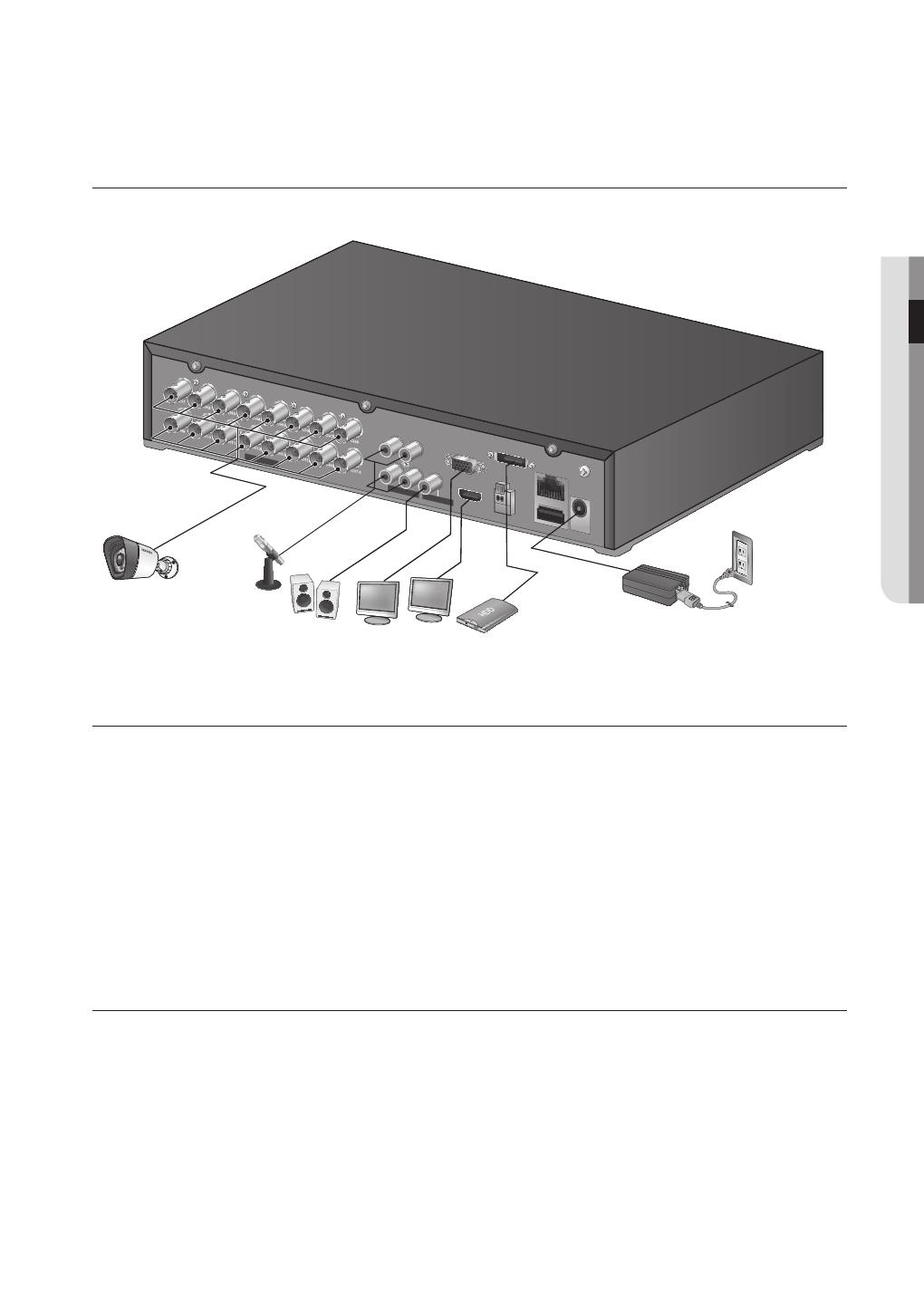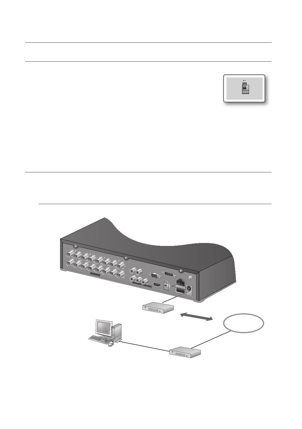
14_ connecting with other device
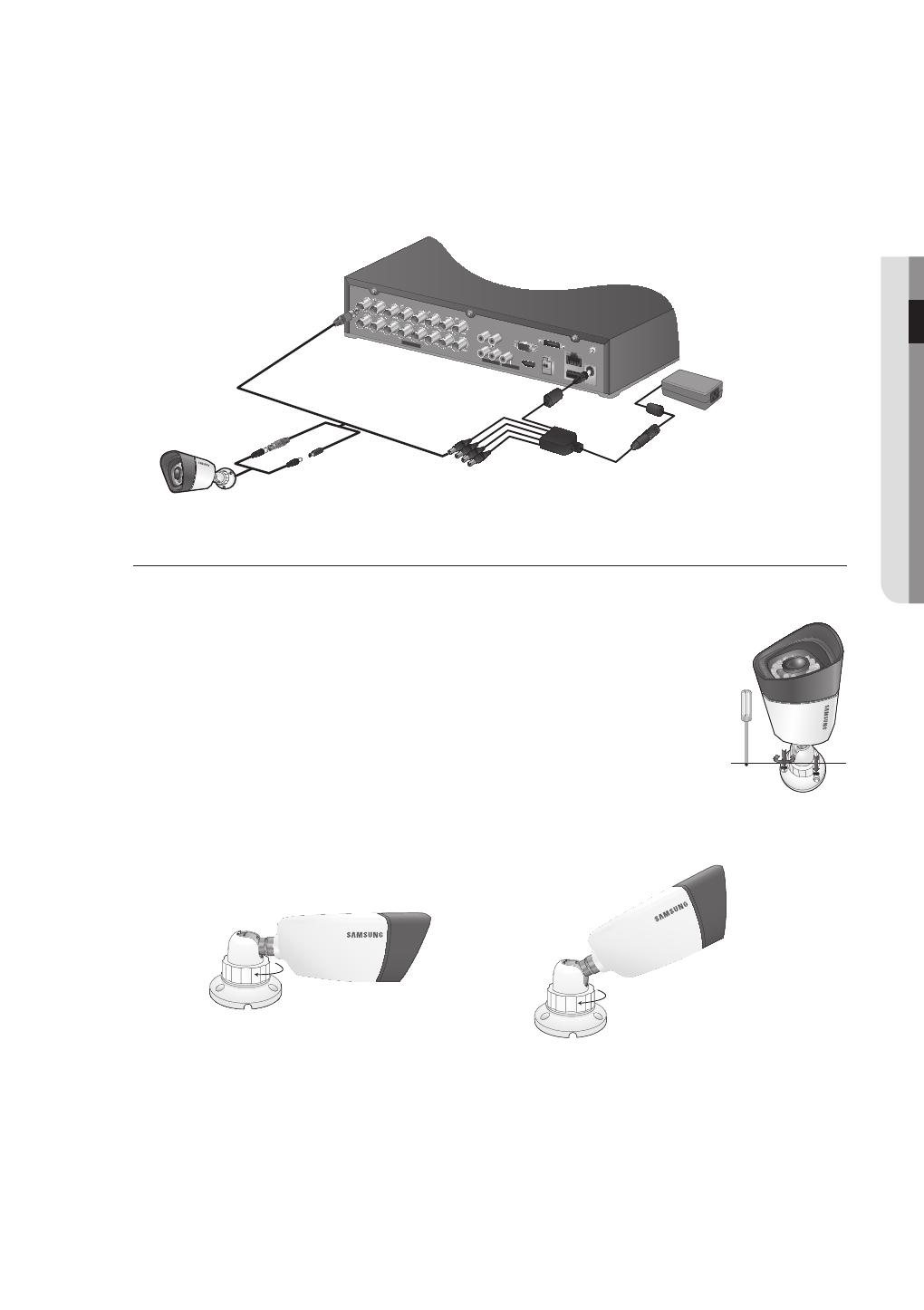
connecting with other device
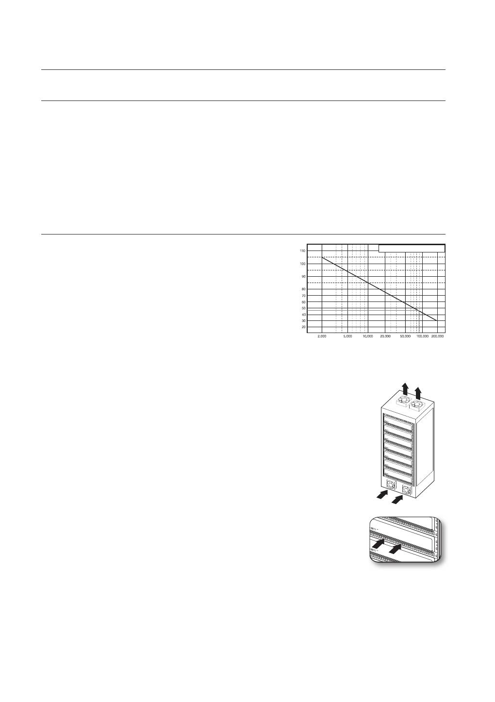
One Year: 24HR X 365 DAY =8,760 HR
Temperature
Unit: ºC
Life (Unit: HOURS)
INSTALLATION
Please take note of the followings before using this product.
•
Do not use the product outdoor.
•
Do not spill water or liquid in the connection part of the product.
•
Do not impose the system to excessive shock or force.
•
Do not pull out the power plug forcefully.
•
Do not disassemble the product on your own.
•
Do not exceed the rated input/output range.
•
Use a certified power cord only.
•
For the product with an input ground, use a grounded power plug.
CHECKING THE INSTALLATION ENVIRONMENT
Samsung Digital Video Recorder (“DVR” hereinafter) is a state-
of-art security device, and contains mass storage hard disk(s)
and critical circuits inside.
When the temperature rises inside the product, the product may
breakdown and the product life be shortened. Please pay
attention to the following recommendations before installation.
The followings are the recommendations when Samsung DVR is installed on a rack.
1. Please ensure that the rack inside is not sealed.
2. Please ensure the air is circulated through the inlet/outlet as shown in the picture.
3. If the DVR or other devices on a rack is to be stacked as in the picture, provide a
suitable space or install a ventilating opening for air circulation.
4. For natural air convection, place the inlet at the bottom of the rack and the outlet on top.
5. It is strongly recommended that a fan motor is installed at the inlet and the outlet for air
circulation. (Please fit a filter at the inlet to screen dust or foreign substances.)
6. Please maintain the temperature inside the rack or surrounding areas between
0°C ~ 40°C (32°F ~ 104°F) as shown in the figure 1.
Rack Mount Instructions - The following or similar rack-mount instructions are
included with the installation instructions :
A) Elevated Operating Ambient - If installed in a closed or multi-unit rack assembly, the
operating ambient temperature of the rack environment may be greater than room
ambient. Therefore, consideration should be given to installing the equipment in an
environment compatible with the maximum ambient temperature specified by the
manufacturer.
B) Reduced Air Flow - Installation of the equipment in a rack should be such that the
amount of air flow required for safe operation of the equipment is not compromised.
C) Mechanical Loading - Mounting of the equipment in the rack should be such that a
hazardous condition is not achieved due to uneven mechanical loading.
D) Circuit Overloading - Consideration should be given to the connection of the equipment to the supply
circuit and the effect that overloading of the circuits might have on overcurrent protection and supply wiring.
Appropriate consideration of equipment nameplate ratings should be used when addressing this concern.
E) Reliable Earthing - Reliable earthing of rack-mounted equipment should be maintained. Particular attention should
be given to supply connections other than direct connections to the branch circuit (e.g. use of power strips).
[Figure 1]
[Figure 2]