Dacor DHW421 Installation guide

Type
Installation guide
Installation Instructions
Discovery
Wall Mount
Range Hoods
Models: DHW301, DHW361, DHW421 and DHW482
Part No. 101743 Rev. J
APPROVED FOR USE WITH ALL DACOR
®
RANGES AND COOKTOPS.
Installation Instructions ...............................................5
Installing the Mounting Bracket ...................................5
Verify the Package Contents .......................................5
Installing Chimney Mounting Bracket ..........................6
Hanging the Range Hood ...........................................7
Connecting the Duct Work ..........................................8
Final Electrical Installation ..........................................8
Final Chimney Assembly .............................................8
Verifying Proper Operation ..........................................9
Installation Checklist ...................................................9
Wiring Diagrams .........................................................10
Notes............................................................................12
Table of Contents
Before You Begin...
Important Safety Instructions .....................................1
Important Information About Safety Instructions .........1
General Safety Precautions ........................................2
Installation Specifications ..........................................3
Performance Specifications ........................................3
Electrical Specifications ..............................................3
Dimensions .................................................................3
Planning the Location .................................................3
Planning and Installing the Duct Work ........................4
All specifications subject to change without notice. Dacor
assumes no liability for changes to specifications.
© 2008 Dacor, all rights reserved.
Important:
Installer: In the interest of safety and to minimize problems, read these installation instructions completely and
carefully before you begin the installation process. Leave these installation instructions with the customer.
Customer: Keep these installation instructions for future reference and the local electrical inspector’s use.
If You Need Help...
If you have questions or problems with installation, contact your Dacor dealer or
the Dacor Customer Service Team. For repairs to Dacor appliances under war-
ranty call the Dacor Distinctive Service line. Whenever you call, have the model
and serial number of the appliance ready. The model and serial number are
printed on the appliance data label (see below for location). Remove the filter(s)
to view the label.
Dacor Customer Service Team
Phone: (800) 793-0093 ex. 2813 (U.S.A. and Canada)
Monday — Friday 6:00 a.m. to 5:00 p.m. Pacific Time
Web site: www.dacor.com
Dacor Distinctive Service (for repairs under warranty only)
Phone: (800) 793-0093 ex. 2822 (U.S.A. and Canada)
Monday — Friday 6:00 a.m. to 5:00 p.m. Pacific Time
Appliance Data Label
The appliance data label contains the model and serial number information
and the electrical requirements.
The label is located inside the hood chassis behind the filter(s). Remove the
filter(s) to view it.
1
Important Information About
Safety Instructions
The Important Safety Instructions and warnings in
these instructions are not meant to cover all possible
problems and conditions that can occur. Use common
sense and caution when installing, maintaining or
operating this or any other appliance.
Always contact the Dacor Customer Service Team
about problems and conditions that you don’t under-
stand.
Important Safety Instructions
Safety Symbols and Labels
DANGER
Immediate hazards that WILL result in severe personal
injury or death.
WARNING
Hazards or unsafe practices that COULD result in
severe personal injury or death.
CAUTION
Hazards or unsafe practices that COULD result in
minor personal injury or property damage.
DANGER
To avoid the possibility of explosion or fire, do not store or use combustible, flammable or explosive vapors and
liquids (such as gasoline) inside or in the vicinity of this or any other appliance. Also keep items that could explode,
such as aerosol cans away from range or cooktop and range hood. Do not store flammable or explosive materials in
adjacent cabinets or areas.
WARNING
WARNING - TO REDUCE THE RISK OF FIRE, ELECTRIC SHOCK, OR INJURY TO PERSONS, OBSERVE THE
FOLLOWING:
a) Use this unit only in the manner intended by the manufacturer. If you have questions, contact the
manufacturer.
b) Before servicing or cleaning unit, switch power off at service panel and lock the service disconnecting
means to prevent power from being switched on accidentally. When the service disconnecting means
cannot be locked, securely fasten a prominent warning device, such as a tag, to the service panel.
WARNING
WARNING – TO REDUCE THE RISK OF FIRE, ELECTRIC SHOCK, OR INJURY TO PERSONS, OBSERVE THE
FOLLOWING:
a) Installation work and electrical wiring must be done by qualified person(s) in accordance with all applicable
codes and standards, including fire-rated construction.
b) Sufficient air is needed for proper combustion and exhausting of gases through the flue(chimney) of fuel
burning equipment to prevent back drafting. Follow the heating equipment manufacturer’s guideline and
safety standards such as those published by the National Fire Protection Association (NFPA), and the
American Society for Heating, Refrigeration and Air Conditioning Engineers (ASHRAE), and the local code
authorities.
c) When cutting or drilling into wall or ceiling, do not damage electrical wiring and other hidden utilities.
d) Ducted fans must always be vented to the outdoors.
CAUTION
For general ventilating use only. Do not use to exhaust hazardous or explosive materials and vapors.
READ AND SAVE THESE INSTRUCTIONS
2
Important Safety Instructions
If the information in this manual is not followed exactly, a fire or explosion may result causing property damage,
personal injury or death.
Do not install or operate this hood if it has been damaged, dropped, has damaged electrical wires or is not work-
ing properly. If the product is damaged when received, immediately contact the dealer or builder.
This range hood must be installed and grounded by a qualified installer according to these installation instruc-
tions.
Install or locate this appliance only in accordance with these installation instructions and the requirements speci-
fied by the manufacturer of the cooktop or range. Improper installation, adjustment, alteration, service or mainte-
nance can cause serious personal injury or property damage.
The customer should not install, repair or replace any part of the range hood unless specifically recommended
in the literature accompanying it. A qualified service technician should perform all other service.
Keep all packaging materials away from children. Plastic bags can cause suffocation.
Do not use an extension cord or adapter plug with this appliance.
The installer must show the customer the location of the fuse box or circuit breaker panel so that the customer
knows where and how to turn the power off.
Read the use and care manual completely before using the appliance. Clean the appliance only as instructed in
the use and care manual. Use only the cleaners specified.
Clean the filter(s) and all grease-laden surfaces often to prevent grease fires and maintain performance. Never
allow the filter(s) to become blocked or clogged. Do not allow foreign objects, such as cigarettes or napkins, to
be sucked into the hood.
Do not tamper with the controls.
If the range or cooktop and range hood are near a window, use an appropriate window treatment. Avoid long
drapes or other window coverings that could blow over the cooktop and hood, resulting in a fire hazard.
Never leave the range or cooktop unattended when a burner (or element) is in use. Boil-overs and greasy spills
may smoke and/or ignite.
Do not leave children or pets alone or unattended in the area where the range or cooktop and range hood are
in use. Never allow children to sit or stand on an appliance. Do not let children play with a range, cooktop or
range hood. Do not store items of interest to children above or around the cooktop, range or range hood.
The minimum vertical distance between the cooking surface and the exterior part of the hood must be no less
than 30” (76.2 cm). The vertical distance may be longer for the range or cooktop being used. Consult the range
or cooktop installation instructions for the minimum and maximum vertical distance from the appliance being
used.
TO REDUCE THE RISK OF FIRE, USE ONLY METAL DUCT WORK.
TO REDUCE THE RISK OF INJURY TO PERSONS IN THE EVENT OF A RANGE TOP GREASE FIRE:
a) SMOTHER FLAMES with a close-fitting lid, cookie sheet or metal tray, then turn off the burner. BE
CAREFUL TO PREVENT BURNS. If the flames do not go out immediately, EVACUATE AND CALL THE
FIRE DEPARTMENT.
b) NEVER PICK UP A FLAMING PAN - you may be burned.
c) DO NOT USE WATER, including wet dish cloths or towels - a violent steam explosion may result.
d) Use a fire extinguisher ONLY if:
You have a Class ABC extinguisher, and you already know how to operate it.
The fire is small and contained in the area where it started.
The fire department is being called.
You can fight the fire with your back to an exit.
WARNING
General Safety Precautions
To reduce the risk of fire, electric shock, serious injury or death when using your appliance, follow basic safe-
ty precautions, including the following:
3
Dimensions
Tolerances: ±1/16” (±1.6 mm), -0 unless otherwise stated
* 18” 1/4 on model DHW482 with exhaust cowling
IMPORTANT: The minimum installed distance from the
hood to the cooking surface must be no less than 30
inches. The minimum specified distance may be higher
for the particular range or cooktop in use. Check the
manufacturers specifications for the cooktop or range.
Planning the Location
WARNING
Observe all governing codes and ordinances during
planning and installation. Contact your local building
department for further information.
Carefully check the location where the hood is to be
installed. The hood should be placed for convenient
access. Make certain that electrical power can be
provided in the selected location.
The hood model selected must be as wide as the
cooktop surface or wider.
All contact surfaces between the hood and any cabi-
nets or walls must be solid and at right angles.
Install the range hood and cooking appliance(s) so
that they can be removed if service is required.
Plan the installation so that all minimum dimensions
are met or exceeded. Dimensions shown above pro-
vide minimum clearances, unless otherwise noted.
Performance Specifications
All Models
Blower
600 CFM* (for single blower units)
1200 CFM* (for dual blower units)
Blower Speeds 4 with electronic speed control
Lights 12 Vac, 20 Watt halogen
Filters Baffle type, dishwasher safe
Exhaust 8-inch
Finish 430 stainless steel
Total Connected
Load
120 Vac, 60 Hz.
(See table below for current draw)
Circuit
Requirement
120 Vac, 15 Amp. grounded,
dedicated circuit, minimum
* At zero inches static pressure
Model Specific
Model Blowers Lights Filters
Maximum
Current
Draw
DHW301 1 2 1 3.4 Amp.
DHW361 1 2 1 3.4 Amp.
DHW421 1 3 1 3.6 Amp.
DHW482 2 4 2 6.8 Amp.
Electrical Specifications
WARNING
The electrical service to the range hood should be
installed only by a licensed electrician.
It is the owner’s responsibility to ensure that the electrical
connection of this appliance is performed by a qualified
electrician. The electrical installation, including minimum
supply wire size and grounding, must be in accordance
with the National Electric code ANSI/NFPA* (or latest
revision) and local codes and ordinances.
* A copy of this standard may be obtained from:
National Fire Protection Association
1 Batterymarch Park
Quincy, Massachusetts 02269-9101
Connect the hood to a junction box supplied by a 120
Vac, 60 Hz. dedicated, grounded, 3-wire (hot, neutral,
ground) circuit protected by a 15 Amp. circuit breaker or
time delay fuse. Locate the junction box a minimum of
17” (43.2 cm) above the bottom of the range hood (for
example, attached to a stud).
Installation Specifications
Chimney
24”
(61.0 cm)
Min. 30 1/4” (76.8 cm)
Max. 42” (106.7 cm)
30” - 36” - 42” - 48”
15”
(38.1 cm)
11 3/4”
(29.8 cm)
5 3/4”
(14.6 cm)
12 1/2”
(31.8 cm)
16 1/4” *
(41.3 cm)
4
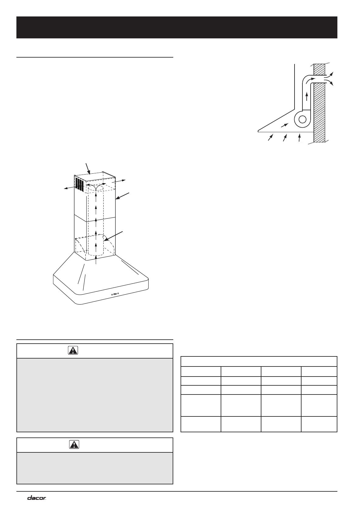
Recirculating Configuration
Recirculating kits AVDH1 and AVDH2 contain the parts
necessary to convert a DHW series hood to a recircu-
lating configuration in instances where exhausting the
hood outside the building is not practical or desired. The
kit consists of a top cap and charcoal filter(s). When
installed, the top cap redirects air flow out the vents in the
sides of the hood chimney assembly. The provided char-
coal filter(s) is/are installed underneath the mesh type
filter(s) included with the hood. The charcoal filter reduces
smoke and fumes before the hood exhaust is vented into
the room. Use kit AVDH1 for models DHW301, DHW361
and DHW421. Use kit AVDI2 for model DHW482.
Ducted Installation - Planning
and Installing the Duct Work
WARNING
To prevent combustion by-products, smoke or odors
from entering the home and to improve efficiency,
tape all duct joints securely.
Use only duct work deemed acceptable by state,
municipal and local codes.
DO NOT install an additional in-line or external
blower to increase the length of the duct run. Even
small differences between blower air flow rates can
greatly reduce the air draw of the hood.
CAUTION
To reduce the risk of fire and to properly exhaust air, be
sure to duct air outside the house or building. Do not
vent exhaust air into spaces within walls or ceilings or
into attics, crawl spaces or garages.
Installation Specifications
All duct work materials (including screws and duct
tape) must be purchased separately by the customer.
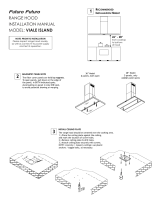
When planning new
duct work, always
look for the shortest,
most direct route to
the outside. Venting
can be done through
the roof or directly
through the back
wall to the outside as
shown.
Local building codes
may require the use
of makeup air systems with ventilation systems that
move air greater than the specified movement rate
(CFM). The specified rate varies based on locale.
Consult a qualified HVAC specialist when designing
the system for the requirements in your area and to
assure optimal performance.
The hood exhaust connects to an 8-inch round duct.
You can increase the duct size over the duct run if
desired. To prevent a back draft, never decrease the
duct size over the run. If existing duct work is smaller
than 8 inches in diameter, remove it and replace it
with 8-inch duct work.
Do not rely on tape alone to seal duct joints. Fasten
all connections with sheet metal screws and tape all
joints with certified silver tape or duct tape. Use sheet
metal screws as required to support the duct weight.
To prevent back-drafts, a damper at the duct outlet
may also be required.
Make sure duct work does not interfere with floor
joists or wall studs.
Calculating the Maximum Duct Run Length
The maximum straight duct length for the hood is 50 feet.
To determine the actual maximum duct run, subtract the
equivalent length of each elbow, transition and cap from
50 feet.
EQUIVALENT LENGTHS
Piece Subtract Piece Subtract
8” 90° elbow 7 feet 10” 90° elbow 5 feet
8” 45° elbow 3 feet 10” 45° elbow 2 feet
3¼” X 10”
to round 90°
transition
25 feet
3¼” X 10” to
8”/10” round
transition
4 feet
Roof cap *
Wall cap with
damper
*
* The equivalent lengths of roof and wall caps vary with
model and configuration. For equivalent length, contact
the manufacturer or a qualified HVAC specialist.
Chimney
Top cap
Duct inside
chimney between
hood and top cap
(not provided)
5
Installation Specifications
Installation Instructions
Unpack the box and verify that all parts listed have been
provided. If any item is missing or damaged, please con-
tact the dealer immediately. Do not install a damaged or
incomplete appliance. Make sure you have everything
required for proper installation before proceeding.
Hood assembly with filter(s)
Chimney assembly (2 piece)
Chimney mounting bracket
Mounting bracket
Duct collar (1 blower units only)
Blower exhaust cowling (2 blower units only)
Mounting and assembly hardware
Use and care manual
A
A
B
C
C
B
D
D
E
F
G
H
G
H
F
E
WARNING
Observe all governing codes and ordinances during installation. Contact your local building department for fur-
ther information.
A qualified technician must complete the installation of this built-in appliance. The owner is responsible to make
sure the hood is properly installed.
Do not install the range hood unless the power supply provided meets the required Electrical Specifications
(see page 3).
To avoid an electric shock hazard and property damage, locate electric wires and water pipes and avoid drilling
or cutting in the vicinity.
The range hood is heavy. To prevent personal injury and property damage install the hood only as specified in
the following instructions and use only the hood mounting bracket provided with the unit. Make sure all screws
used to mount and assemble the hood are tight. Failure to properly anchor the hood to the wall may result in
personal injury due to the unit falling. Hanging the range hood requires two people. Do not attempt to lift the
hood without assistance.
Verify the Package Contents
Duct Work Design Tips
Wherever possible, reduce the number of transitions
and turns to as few sharp angles as possible. Two
staggered 45° angles are better than one 90°.
Keep turns as far away from the hood exhaust as
possible, and as much space between bends as pos-
sible.
For best performance, use round duct instead of rect-
angular, especially when elbows are required.
If multiple elbows are used, try to keep a minimum of
24 inches straight duct between them.
Avoid “S” or “back to back” use of adjacent elbows.
In regions where the weather gets extremely cold,
use thermal breaks, such as a short section of
non-metallic duct, to avoid indoor heat loss. Locate
the break as close as possible to the outside pass
through point.
Do not use flexible metal duct.
DO NOT use duct work that is smaller in cross-sec-
tional area than the recommended types above.
6
Installation Preparation
NOTE: If installing the hood in the recirculating configu-
ration (recirculating kit # AVDH1 or AVDH2), consult the
instructions that come with the kit before starting installa-
tion.
1. Attach the hood
junction box to
the top of the
hood using two
machine screws
as shown.
2. Remove the ship-
ping tape holding
the damper flaps
closed. Make
sure all the flaps open and close freely before pro-
ceeding.
3. Remove the filter(s) to reduce weight and avoid dam-
age.
Installing the Mounting Bracket
NOTE: The mounting hardware
included with the hardware packet
is suitable for mounting to brick and
masonry only. If mounting the range
hood to drywall, Dacor strongly
recommends the using a sturdy
anchoring system designed for
use with drywall. In addition, Dacor
strongly recommends that you
install a reinforced mounting block
between the studs behind all hood
mounting locations.
1. Using a pencil, draw a level
horizontal line on the wall
where the bottom of the hood will be. The line must
be at least 30 inches above the cooking surface.
2. On the hood itself, measure the distance between
the bottom of the hood and the top of the mounting
bracket hole on the hood being installed. Using a
pencil, draw a short line on the wall the same dis-
tance above the horizontal line drawn in step 1. You
will use this line to determine the height of the mount-
ing bracket when attached to the wall.
Installation Instructions
C
L
C
L
Hood center
line
Height of
mounting
bracket
(step 2)
C
L
C
L
Line up
center hole with
center line
Line horizontal
line up with this
edge
Mounting
bracket
Anchor
3. Locate the verti-
cal center line for
the hood mount-
ing location on
the wall. Mark the
center line with a
six inch vertical
line that intersects
the line drawn in
step 2.
4. Make sure the
mounting location
is properly rein-
forced so that it
will hold the weight
of the hood.
5. Find the mounting bracket in the shipping box. Place
it against the wall where the two lines cross. Center
it vertically and line the top of the bracket up with the
horizontal line as shown.
6. Making sure the bracket is level, use a pencil to
mark the mounting hole locations through the bracket
holes.
7. Drill the mounting holes. The method for drilling the
holes depends on the type of mounting surface...
If mounting the hood to brick or masonry:
Drill three 5/16” x 1 1/2” holes in the locations
marked.
Insert three of the provided wall anchors into the
holes. The anchors provided are for attaching the
hood to masonry or brick only.
Top of mounting
bracket hole
Remove
tape
7
If mounting the hood to drywall:
Drill three appropriate sized pilot holes for the
mounting hardware being used. The drywall
mounting hardware must be purchased sepa-
rately.
8. Attach the mounting bracket securely to the wall.
Installing Chimney Mounting
Bracket
1. Locate the chimney mounting bracket and position it
against the ceiling as shown. Center it on the hood
center line.
2. Mark the ceiling and the wall in two places each,
through the holes in the bracket.
3. Drill four 5/16” holes through the four spots marked
on the ceiling and wall.
4. Insert the four of the provided wall anchors into the
four holes on the ceiling and wall.
5. Attach the chimney mounting bracket using four
included 1 1/2” screws.
Hanging the Range Hood
1. Lift the hood up on both sides and put the mounting
hole on the top of the hood over the lip of the mount-
ing bracket. Gently lower it into place.
2. Insert two provided machine screws into the two
holes above the mounting bracket on the range hood.
Tighten the screws until they make contact with the
bracket, then tighten them as necessary to make
minor leveling adjustments to the hood.
3. Insert two machine screws
through the front of the
mounting bracket and
tighten them into place.
4. Install the duct collar or
exhaust cowling on the top
of the hood assembly as
shown below, using the
screws included with the hood.
Installation Instructions
Mounting
bracket
Anchors
Chimney
mounting bracket
Mounting
bracket
Duct Collar Installation -
Models DHW301, DHW361
and DHW421
Exhaust Cowling Installation
- Model DHW482
8
Installation Instructions
Connecting the Duct Work
WARNING
Do not use screws to attach the duct work to the hood
exhaust outlet. Use duct tape only. Screws may prevent
the damper flaps on the top of the hood from opening.
If installing the unit with a recirculating kit, skip to Final
Electrical Installation. Otherwise, install the duct work
between the hood exhaust and the previously installed
duct work. Attach the duct to the hood exhaust with duct
tape alone. Use sheet metal screws (not provided) and
duct tape on the remaining joints.
Final Electrical Installation
WARNING
To avoid electric shock or fire hazard, prior to con-
necting the electrical wiring to the hood, make sure
that power to the hood power supply line is turned
off at the circuit breaker panel or fuse box.
Improper connection of the hood electrical wiring
may create an electric shock or fire hazard and may
result in damage to the hood’s electrical system.
See page 3 for specifications.
Do not ground the hood to the neutral (white) power
supply wire. Connect the hood ground wire to a
separate, proper ground wire installed by a licensed
electrician.
Make sure all wire used is capable of handling the
total connected load. See page 3.
Connect the house power supply wires to the wires
coming out of the hood junction box, inside the chim-
ney:
1. Connect the white wire
from the hood to the
neutral (white) power
supply wire.
2. Connect the black wire
from the hood to the hot
(black) power supply
wire.
3. Connect the green
and yellow wire from
the hood to the house
ground (green) wire from
the junction box.
Final Chimney Assembly
WARNING
Be careful not to pinch the electrical wires while
assembling the chimney.
1. Remove the protective plastic covering from both
pieces of the chimney assembly. Do not remove the
protective tape strips from the inside of the chimney.
They protect the telescoping pieces from scratching
during installation.
2. Carefully slide both sections together so that only the
vents on the top section show.
3. Hold the chimney vertically with the vents up.
Chimney
Chimney
mounting
bracket
Vent
Duct work
Hood
House power
supply wires
Wires to blower
inside hood
chassis
9
Installation Instructions
4. Carefully put the chimney over the top of the duct
work extending out of the top of the hood, taking care
not to scratch the surfaces. Make sure the wiring is
tucked in behind the chimney.
5. Move the chimney up toward the ceiling. Line up the
holes on the side of the chimney, above the vents,
with the holes on the side of the chimney mounting
bracket.
6. Attach the sides of the chimney to the bracket using
two sheet metal screws, one on each side.
7. Carefully, slide the bottom portion of the chimney
down until it rests on the top of the range hood.
Verifying Proper Operation
1. Reinstall the range hood filter(s) before operation.
2. Make sure power is switched on at the circuit breaker
panel or fuse box.
3. If the control panel is not lit, remove the filter(s) and
turn on the main power switch located behind the
filters on the underside of the hood. Replace the
filter(s).
4. Touch the light key. Verify that all the lights come on.
5. Touch the light key again to turn the lights off.
6. Touch the blower “+” key once and release. Verify
that one light is showing on the blower speed indica-
tor and that the blower is on at low speed.
7. Touch and release the blower “+” repeatedly, three
times. Verify that with each touch of the key the num-
ber of lights on the speed indicator increases and that
the blower speed increases accordingly.
8. Touch and hold the blower “-” key until the blower
turns off.
If the hood fails to operate properly:
Verify that power is supplied to the hood.
Check the electrical connections to ensure that the
installation has been completed correctly.
Repeat the above test.
If the hood still does not work, contact Dacor
Distinctive Service at (800) 793-0093 ex. 2822. Do
not attempt to repair the appliance yourself. If you
need service, be sure to have the model and serial
numbers available when you call. See the inside
cover for location.
Do not attempt to repair the appliance yourself. Dacor
is not responsible for the cost of correcting problems
caused by a faulty installation.
Installation Checklist
WARNING
To ensure a safe and proper installation, the follow-
ing checklist should be completed by the installer
to ensure that no part of the installation has been
overlooked.
Proper installation is the responsibility of the home-
owner. The importance of proper installation of your
Dacor range hood cannot be overemphasized.
Is the mounting bracket properly attached to the wall
according to the instructions on page 6?
Is the duct work completely installed? Are all joints
attached with sheet metal screws and wrapped with
duct tape? See pages 4 and 8?
Is the range hood wired and grounded according to
these instructions and in accordance with all appli-
cable electrical codes? See pages 3 and 8.
Are the filters properly installed according to the use
and care manual?
Has proper operation been verified?
Has the warranty been activated on-line or the war-
ranty card filled out completely and mailed?
10
Wiring Diagrams
Please note—the layout on the PC Board shown above may vary—
however all wires are coded and the connections on the PC Board are also
coded with the same number/letters.
MAIN POWER
SWITCH
TRANSFORMER
EXTERNAL BLOWER
CONNECTION
TRANSFORMER
TO BLOWER MOTOR
YELLOW/GREEN
LIGHT FIXTURES
LIGHT FIXTURES
Single Blower Models: DHW301, DHW361, DHW421
11
Please note—the layout on the PC Board shown above may vary—
however all wires are coded and the connections on the PC Board are also
coded with the same number/letters.
MAIN POWER
SWITCH
YELLOW/GREEN
EXTERNAL BLOWER
CONNECTION
TRANSFORMER
TRANSFORMER
TO BLOWER
MOTOR
TO BLOWER
MOTOR
LIGHT FIXTURES
LIGHT FIXTURES
Double Blower Model: DHW482
12
Notes
Dacor ● 14425 Clark Avenue, City of Industry, CA 91745 ● Phone: (800) 793-0093 ● Fax: (626) 403-3130 ● www.dacor.com
  • Page 1 1
  • Page 2 2
  • Page 3 3
  • Page 4 4
  • Page 5 5
  • Page 6 6
  • Page 7 7
  • Page 8 8
  • Page 9 9
  • Page 10 10
  • Page 11 11
  • Page 12 12
  • Page 13 13
  • Page 14 14
  • Page 15 15
  • Page 16 16

Dacor DHW421 Installation guide

Type
Installation guide

Ask a question and I''ll find the answer in the document

Finding information in a document is now easier with AI