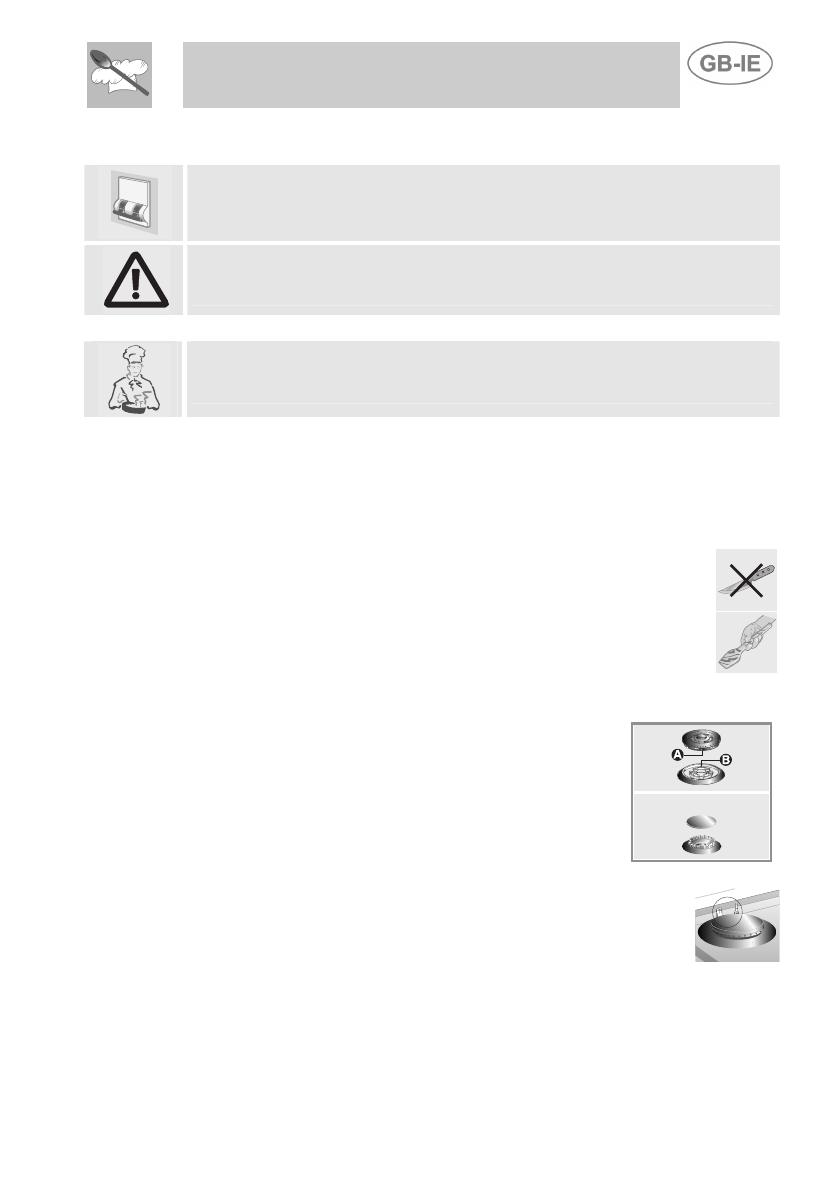
Instructions for the user
6 CLEANING AND MAINTENANCE
Before any intervention, disconnect the appliance from the mains.
Never use a steam jet to clean the appliance.
6.1 Cleaning the stainless steel
To keep stainless steel in good condition it should be cleaned regularly
after use. Let it cool first.
6.1.1 Routine daily cleaning
To clean and preserve the stainless steel surfaces, always use only
specific products that do not contain abrasives or chlorine-based acids.
How to use: pour the product on a damp cloth and wipe the surface, rinse
thoroughly and dry with a soft cloth or chamois leather.
6.1.2 Food stains or residues
Under no circumstances must metallic scourers or sharp
scrapers be used: they will damage the surface.
Use normal non-abrasive products for steel, and a wooden or
plastic tool if necessary.
Rinse thoroughly and dry with a soft cloth or chamois leather.
6.2 Cleaning of cooking hob components
To facilitate cleaning, panstand grids, caps, flame-
spreader crowns and burners are all removable;
wash with warm water and non-abrasive detergent,
taking care to remove allstubborn food residues. Wait
for all parts to be fully dry before remounting. Refit
the caps on the respective flame-spreader crowns,
making sure that notchesA align with burner pins B .
To work well, the ignition plugs and thermocouples must
always be very clean. Check them frequently and clean
them with a wet cloth if necessary. Any dry residue should
be removed with a toothpick or a needle.
33


