Troy-Bilt 21A-675B766 User manual
- Category
- Mini tillers
- Type
- User manual

Operator's Manual
r®
Rear-tine Tiller
Model 675B
Model 675B Shown (bumper styles vary)
IMPORTANT: READ SAFETY RULES AND INSTRUCTIONS CAREFULLY
WARNING: This unit isequippedwith an internal combustion engineand should notbe usedon or nearany unimproved forest-covered, brush-covered or
grass-covered land unless theengine's exhaust system isequipped with aspark arrester meeting applicable local or state laws(if any). If aspark arrester isused, it
should be maintained in effective working order by the operator. In the State of California the above is required by law (Section 4442 of the California Public
ResourcesCode). Other states may havesimilar laws. Federallaws apply on federal lands.A spark arrester for the muffler isavailable through your nearest engine
authorized service dealeror contactthe service department P.O.Box 361131 Cleveland,Ohio44136-0019.
TROY-BILT LLC, P.O. BOX 361131 CLEVELAND, OHIO 44136-0019
PRINTEDIN U.S.A. FORMNO. 769-00586B
9/13/04

TABLEOFCONTENTS
Content Page Content Page
Customer Support 2 Maintenance 16
Safety 3 Troubleshooting 23
Assembly 6 Parts List 24
Features and Controls 9 Warranty Back Cover
Operation 11
FINDINGMODELNUMBER
This Operator's Manual is an important part of your new lawn tractor. It will help you assemble, prepare and maintain the
unit for best performance. Please read and understand what it says.
Before you start assembling your new equipment, please locate the model plate on the equipment and
copy the information from it in the space provided below. A sample model plate is also given below. You can
locate the model plate by looking at the rear of the tine shield. This information will be necessary to use the
manufacturer's web site and/or help from the Customer Support Department or an authorized service dealer.
OTRDV-BILT T,OV-BmLTLLC
P. O. BOX 361131
www.troybilt.com CLEVELAND,OH44136
330-558-7220
,. 1-800-520-552_
Copy the model number here:
Copy the serial number here:
CUSTOMERSUPPORT
PleasedoNOTreh/m thel/nit totheretailer withoutfirstcontactingCustomerSupport.
If you have difficulty assembling this product or have any questions regarding the controls, operation or maintenance of
this unit, you can seek help from the experts. Choose from the options below:
Visit troy-bilt.com for many useful suggestions. Click on Customer Support button and you
will get the four options reproduced here. Click on the appropriate button and help is
immediately available.
/;/ ,> ;'V }/ )
..... f ; @; t ;D
j;_ ?" #'s " 4t, ' F_ i/!s ,
* ;,, #FOX }_ j,"
,v yO, ,_;7f'_;:'
_ 7>,,,,
,,, >,, rL;," ¢j ,_ <# ft, *x J ,7;; _
'_,-., _tf';_'ivc ,l
If you prefer to reach a Customer Support Representative, please call 1(800) 520-5520.
The engine manufacturer is responsible for all engine-related issues with regard to
performance, power-rating, specifications, warranty and service. Please refer to the engine
manufacturer's Owner's/Operator's Manual, packed separately with your unit, for more
information.

SECTION1: SAFETY
This machine meets voluntary safety stan-
dard B71.8-1996, which is sponsoredbythe
Outdoor Power Equipment Institute, Inc.,
and is published by the American National
Standards Institute.
WARNING
The engine exhaust from this productcontains
chemicals known to the State of California to
cause cancer, birth defects or other reproduc-
tive harm.
SafetyAlertSymbol
,_ This is a safety alert symbol. It is used
in this manual and on the unit to alert
you to potential hazards. When you see
this symbol, read and obey the
message that follows it. Failure to obey
safety messages could result in
personal injury or property damage.
Recoil
Rope
Starter
Wheel GearLever
ReverseClutch Control_ I
ForwardClutch Lever
/
ForwardClutchLever
Depth
Regulator
Lever
Figl/re 1-1
CounterRotatingTines
Training
1. Carefullyreadthis Own-
er's Manual,the separate
EngineOwner's Manual,
andanyotherliteratureyou may receive.Be
thoroughly familiar with the controls and
the proper use ofthe tiller and its engine.
Know howto stop the unit and disengage
the controls quickly.
2. Neverallow childrento operatethetiller.
Neverallow adultsto operatethetiller with-
out proper instruction.
3. Keepthe area of operationclear of all
persons, particularly children and pets.
4. Keepin mind that the operatoror useris
responsiblefor accidents or hazardsoccur-
ring to other people,their property,and
themselves.
Preparation
1. Thoroughly inspect the areawherethe
tiller is to be usedand removeall foreign
objects.
2. Besure all control leversare released
andthe WheelGearLeverisin ENGAGEpo-
sition beforestarting the engine.
3. Donot operatethetiller without wearing
adequateouter garments.Avoid loosegar-
ments or jewelry that could getcaught in
moving parts.
4. Donotoperatethetillerwhenbarefootor
wearingsandals,sneakers,orlightfootwear.
Wearprotectivefootwearthat willimprove
footingonslipperysurfaces.
5. Donottillnearundergroundelectriccables,
telephonelines,pipesor hoses.If in doubt,
contactyourtelephoneor utilitycompany.
6.Warning:Handlefuelwith care;itis highly
flammableandits vaporsareexplosive.Take
thefollowingprecautions:
a. Storefuel in containers specifically
designedfor this purpose.
b.Thegascapshall neverberemovedor
fuel addedwhile the engine is run-
ning.Allow theengineto coolfor sev-
eral minutes beforeaddingfuel.
c. Keepmatches,cigarettes, cigars,
pipes, openflames, and sparksaway
from the fueltank and fuel container.
d. Fill fuel tank outdoors with extreme
care. Neverfill fueltank indoors. Use
a funnel or spout to prevent spillage.
e. Replaceall fueltank and container
caps securely.
f. If fuel isspilled, do notattemptto start
the engine,but movethe machine
awayfrom the area of spillageand
avoidcreating anysourceof ignition
until fuelvapors havedissipated.
7. Nevermakeadjustments whenengineis
running (unless recommendedby manu-
facturer).
Operation
1. Do not put hands or feet near or under
rotating parts.
2. Exerciseextremecautionwhen on or
crossing gravel drives,walks, or roads.
Stay alertfor hidden hazardsor traffic. Do
not carry passengers.
3. After striking a foreign object,stop the
engine,removethewire from the spark
plug wire and prevent it from touching the
spark plug,thoroughly inspectthe machine
for any damage,and repairthe damagebe-
fore restarting and operatingthe machine.
4. Exercisecautionto avoidslipping or fall-
ing.

5.Iftheunitshouldstarttovibrateabnormally,
stoptheengine,disconnectthesparkplug
wireandpreventitfromtouchingthespark
plug,andcheckimmediatelyforthecause.Vi-
brationisgenerallyawarningoftrouble.
6.Stoptheengine,disconnectthespark
plugwireandpreventitfromtouchingthe
sparkplugwheneveryouleavetheoperat-
ingposition,beforeuncloggingthetines,
orwhenmakinganyrepairs,adjustments
orinspections.
7.Takeallpossibleprecautionswhenleav-
ingthemachineunattended.Stoptheen-
gine.Disconnectsparkplugwireandmove
itawayfromthesparkplug.MoveWheel
GearLevertoENGAGE.
8.Beforecleaning,repairing,orinspect-
ing,stoptheengineandmakecertainall
movingpartshavestopped.Disconnect
thesparkplugwireandpreventitfrom
touchingthesparkplugtopreventacci-
dentalstarting.
9.Alwayskeepthetillertinehoodflap
down.
10.Neverusethetillerunlessproper
guards,plates,orothersafetyprotectivede-
vicesareinplace.
11.Donotrunengineinanenclosedarea.
Engineexhaustcontainscarbonmonoxide
gas,adeadlypoisonthatisodorless,col-
orless,andtasteless.
12.Keepchildrenandpetsaway.
13. Neveroperate thetiller underengine
powerifthe WheelGearLever is in DIS-
ENGAGE(FREEWHEEL).In this position,
thewheels will notholdthe tiller back
andthe revolvingtines could propelthe
tiller rapidlybackward,possiblycausing
lossofcontrol. Always move theWheel
GearLeverto ENGAGEbeforestarting the
engine or engagingthe tines4Nheelswith
the Forward Clutchor the ReverseClutch.
14. Beawarethat the tiller may unexpect-
edly bounceupward orjump backward if
the tines should strike extremely hard
packedsoil, frozen ground, or buried ob-
stacleslike largestones, roots, or stumps.
If in doubt aboutthe tilling conditions, al-
ways usethe following operating precau-
tions to assist you in maintaining control
of thetiller:
a. Walk behindandtoone sideof the
tiller, usingone handon thehan-
dlebars.Relax yourarm, butusea
securehandgrip.
b. Useslowerenginespeeds.
c. Clear thetilling areaof all large
stones,rootsand other debris.
d. Avoidusingdownwardpressureon
handlebars.If needbe, useslight
upwardpressureto keepthe tines
from diggingtoo deeply.
e. Beforecontacting hardpackedsoil
at the endof a row,reduceengine
speedand lift handlebarsto raise
tines out of thesoil.
f. In anemergency, stoptines and
wheels by releasingwhichever
ClutchLeverisengaged.Donotat-
tempttorestrainthe tiller.
15. Donot overloadthe tiller's capacityby
attempting to till too deeplyat too fast a
rate.
16. Neveroperatethetiller at high trans-
port speedson slippery surfaces. Lookbe-
hind and usecarewhen backingup.
17. Donot operatethetiller on aslopethat
is too steep for safety.When onslopes,
slow down and makesure you havegood
footing. Neverpermit thetiller to freewheel
down slopes.
18. Neverallow bystanders nearthe unit.
19. Onlyuseattachmentsand accessories
that are approved byGardenWay Inc.
20. Usetiller attachmentsand accessories
when recommended.
21. Neveroperatethetiller withoutgoodvis-
ibility or light.
22. Neveroperatethetillerifyouaretired,or
undertheinfluenceofalcohol,drugsormedi-
cation.
23.Operatorsshallnottamperwiththeengine-
governorsettingsonthemachine;thegovernor
controlsthemaximumsafeoperatingspeedto
protecttheengineandallmovingpartsfrom
damagecausedbyoverspeed.Authorizedser-
viceshallbesoughtifa problemexists.
24. Donottouchenginepartswhichmaybe
hotfromoperation.Letpartscooldown
25.Pleaseremember:Youcanalwaysstopthe
tinesandwheelsbyreleasingtheForward
ClutchLeverortheReverseClutchControl
(whicheverleveryouhaveengaged)orbymov-
ingtheThrottleControlLeverto STOP.
26.Toloador unloadthetiller,seetheinstruc-
tionsinSection4 ofthis Manual.
27. Useextremecautionwhenreversingor
pullingthemachinetowardsyou.
28.Starttheenginecarefullyaccordingtoin-
structionsandwithfeetwellawayfromthe
tines.
29.Neverpickupor carryamachinewhilethe
engineisrunning.
MaintenanceandStorage
1. Keepthe tiller, attachmentsand acces-
sories in safeworking condition.
2. Checkall nuts, bolts, and screws at fre-
quent intervalsfor proper tightness to be
surethe equipmentis in safeworking con-
dition.
3. Neverstorethetillerwithfuelinthefueltank
insideabuildingwhereignitionsourcesare
presentsuchashotwaterandspaceheaters,
furnaces,clothesdryers,stoves,electricmo-
tors,etc.).Allowenginetocoolbeforestoringin
anyenclosure.
4.Toreducethechancesofafirehazard,keep
theenginefreeofgrass,leaves,or excessive
grease.
5. Storegasolineina cool, well-ventilated
area,safelyawayfrom anyspark- or flame-
producingequipment.Storegasolinein an
approvedcontainer,safelyawayfrom the
reachofchildren.
6. Referto the storageinstructions in the
Maintenancesectionofthis Manualandthe
separateEngineOwner'sManualfor in-
structions ifthe tiller is to bestored foran
extendedperiod.
7. Neverperform maintenancewhiletheen-
gine is running orthe spark plug wire is
connected,exceptwhenspecificallyin-
structedto do so.
8. If thefueltank hasto be drained,dothis
outdoors.

SafetyDecals
Foryour safetyand the safety of others,
various safety and operationaldecalsare
located on your unit (seeFigure 1-2 be-
low).
Keepthe decalscleanand legible atall
times. Contactyour localservice dealeror
the factory for replacementsif anydecals
are damagedor missing.
Referto the Parts List in this manualfor
decallocations, partnumbersand ordering
instructions.
TineWarning
StartingStabilization
Message(onengine)
ControlDescription
(onControlPanel)
WarningMessages
(onlinehood)
HotSurfacesMovingBelts
Warning(onbeltcover)
Figure 1-2:LocationofSafetyand OperatingDecals
OperatingSymbols
Varioussymbds(shownhere,withworddescriptions)
mayheusedon'dle'dllerandengine.
NOTE:Yourunitmaynothaveallof_esymbds.
FAST SLOW STOP
I-.-I I,I
CHOKE CHOKE
ON OFF
TILLERDIRECTION
R
REVERSE
<--
LEVERDIRECTION
ROTATINGTINES
TO AVOID SERIOUS INJURY:
* READTHEOPERATOR'SMANUAL.
* KNOWLOCATIONSANDFUNCTIONSOFALLCONTROLS.
* KEEPALLSAFETYDEVICESANDSHIELDSIN PLACEAND WORKING.
. NEVERALLOWCHILDRENORUNINSTRUCTEDADULTSTO OPERATETILLER.
° SHUTOFFENGINEAND DISCONNECTSPARKPLUGWIREBEFOREMANUALLYUN-
CLOGGINGTINESORMAKINGREPAIRS.
. KEEPBYSTANDERSAWAYFROM MACHINE.
. KEEPAWAYFROMROTATINGPARTS.
° USEEXTREMECAUTIONWHEN REVERSINGOR PULLINGTHEMACHINETOWARDS
YOU.

SECTION2: ASSEMBLY
WARNING: Toprevent
personalinjury or property
damage,do notstartthe engine
until all assemblysteps are
completeandyou haveread
and understandthesafetyand
operatinginstructions in this
Manual.
Introduction
Carefullyfollow these assemblysteps to
correctly prepareyour tiller for use. It is
recommendedthatyou readthis Sectionin
its entirety beforebeginning assembly.
Inspect unit
Inspect the unitandcarton for damageim-
mediatelyafter delivery.Contactthe carrier
(trucking company) if you find or suspect
damage. Inform them of the damageand
request instructions for filing a claim. To
protect your rights, put your claim in writ-
ing and mailacopyto the carrierwithin 15
days after the unit has beendelivered.
Contact usatthe factory ifyou needassis-
tance in this matter.
Unpackingand Assembly
Instructions
STEP1:UNPACKINGINSTRUCTIONS
1. Removeanycard-board inserts and
packaging materialfrom the carton. Re-
move anystaples from the bottom ofthe
carton and removethe carton.
2. Cutthe large,plastictie strapthat se-
curesthe transmissiontubeto theshipping
pallet. Leavethe handlebarson top ofthe
tiller to avoiddamaginganycables.
3. A bag with loosehardware is insidethe
literature envelope.Checkthe contents
againstthe following list and Figure2-1.
Contactyour local dealeror the factory if
anyitems aremissing or damaged.
NOTE:Forelectric start units, a second
hardwarebagis located nearthe battery.
4. Thetiller is heavy.Youshould not at-
tempt to removeit from the shipping plat-
form until instructed to do so in these
"Assembly" steps.
HardwareBagPartsList
Ref. Qty. Description
1 2 3/8-16 x 1"HexHd. Screw
2 1 KeyedWasher
3 1 WheelGearLeverKnob
4 1 Height Adjustment Flange
(SeeFigure2-2)
5 2 3/8" FlatWasher
6 2 #10 Lockwasher
7 2 3/8"-16Nylock Lock Nut
8 2 #10-32 x 1/2" Rnd HdScrew
9 2 #10-32 Nut
18 1 CotterPin (not used)
11 4 PlasticTieStrap (2 not used)
Tools/ MaterialsNeeded
forAssembly
(1) 3/8" open-endwrench*
(2) 9/16" open-endwrench*
(1) 7/8" open-endwrench"
(1) Scissors (totrim plasticties)
(1) Ruler
(1) Smallboard(totapplastic knobon
lever)
(1) Tirepressuregauge
(1) Cleanoil funnel
(1) Clean,high-quality motor oil. Referto
the separateEngineOwner'sManual
for motor oil specificationsand quan-
tity required.
* Adjustable wrenchesmay be used.
IMPORTANT:Motoroil must beaddedto
the enginecrankcasebeforetheengineis
started. Followthe instructions inthis
"Assembly" Sectionand in the separate
EngineOwner'sManual.
NOTE: LEFT and RIGHT sides of the
tiller are as viewed from the
operator's position behind the
handlebars.
STEP2: ATTACHHANDLEBARS
1. Cutthe large, plastic cableties that se-
curethe handlebarendsto the handlebar
mounting tabs onthe transmission top
cover.
2. Gentlylift handlebar(do not overstretch
attachedcable)and placehandlebarcross-
brace(B, Figure2-3) in front of curved
height adjustment bracket (C).
4
O@ 8
7 10 11
Figure2-1:Loosehardware(shownin re-
ducedsize).
Figure2-2: Handlebarheightadjustmentuses
the flangeheadscrew.
Figure2-3:Forwardclutchcontrolcablenot
shownforclarity.
3. Withtheforwardclutchcable (N, Fig-
ure 2-4) ontheinside ofhandlebar,posi-
tion the handlebarends on the outside of
thetwo mounting tabs (M, Figure2-3) on
thetransmission top cover.
NOTE:Thecurvedhandlebarheightadjust-
ment bracket appearsasshown in C, Fig-
ure 2-3 for non-electric start units. For
electricstart units,the bracketisloosened
and moved to one side.
4. Loosely attachthe handlebarsto the
mounting tabs with two 3/8-16 x 1"screws
(headsof screws goto insideoftabs), 3/8"
flat washersand 3/8"-16 lock nuts (O,Fig-
ure2-4).

Figure2-4: Attachhandlebars.
5. Move the handlebarsup or downto
align thethreaded holein the cross-brace
with one of thefour slots in the curved
heightadjustmentbracket.Placethe keyed
washer (E,Figure2-3) on the flange head
height adjustment screw (F)with the
raised keys(edges)of the washer facing
down.
6. Threadthe height adjustment screw (F,
Figure2-3) into the hole in the handlebar
cross-brace, making surethat the raised
keysonthe washer fit intothe slot on the
height adjustment bracket. Tightenthe
height adjustment screw securely. Next,
securelytighten thetwo screws and nuts
in the ends of the handlebar (M, Figure2-
3).
7. Toremovethe tiller from its shipping
platform, first carefully unwrap the wheel
gearcable(with attachedlever- seeFigure
2-5) from around the chassis. Movethe
WheelGearLever(G) to the DISENGAGE
position--this allows the wheelsto rotate
freely. Usethe handlebarsto roll the tiller
off the platform.
Figure2-5:CarefullyunwrapWheelGearLe-
verandmovelevertoDISENGAGE.
IMPORTANT:Usethe DISENGAGE
position onlywhenthe engineis not
running. Beforestartingthe engine,the
WheelGear Levermust be placedin the
ENGAGEposition (seeSection3 for
details).
STEP3: ATTACHREVERSECLUTCH
CONTROLCABLE
1. Carefullyunwrapthe reverseclutch
control cable(H, Figure2-6) from its ship-
ping position and route it upalong the in-
sideedgeofthe left sidehandlebar.A knob
and large hexnut (I) is installed on theca-
ble.
Left Side ReverseClutch
Handlebar Control Knob
SlotinControlPanel
'1
Figure2-6:Attachreverseclutchcontrolas-
semblytodotted holeinhandlebarpanel.
2. Insert the cableinto the slot in the con-
trol paneland fit the threadedassembly
intothe holein theslot (seeFigure2-6). Be
surethat the flat sideof the threadedas-
sembly is aligned with theflat side of the
hole.Slidethe hexnut (I) upthecableand
tighten it securely.
3. Testthe function ofthe reverseclutch
control cableby pulling the knob out and
releasingit. Theknob should return to its
neutral position againstthe taperedbush-
ing. If it doesn't, contact your local dealer
or the factory for technical.
STEP4: ATTACHFORWARDCLUTCH
CONTROLCABLE
1. Removeany fasteners (rubber bands,
tape, etc.) that may securethe Forward
ClutchControllevers (J, Figure2-7) to the
handlebar.
Figure2-7: Forward ClutchControllevers(J).
Forwarddutch controllinkage(K).
2. Theforward clutch control cable (with
attachedspring) is hanging loosely near
the right-side wheel. Beingcareful not to
kink or stretch the cable,insert the z-con-
nector (L, Figure2-8 - end of the spring)
into the hole atthe end ofthe forward
clutch control linkage(K, Figure2-7).
Figure2-8
3. Attachthecableadjuster(A,Figure2-9)
to the bracketon the right-side handlebar.
Usetwo 1/2"wrenchesto loosenthetwo
jam nuts (B)just enoughto slidethe cable
adjuster ontothe bracket.Then handtight-
enthe jam nuts.
NOTE: The Wheel Gear Lever will be
installed later in this procedure.
Figure2-9

CAUTION: Incorrect cable
adjustment couldcausethe
wheelsandtines to rotate
unexpectedly.Follow
adjustment procedures
carefully. Failureto do socould
result in personalinjury or
property damage.
4. Checkfor correct spring/caNetension
as instructed in Section 5, Checkingand
Adjusting Forward Clutch Belt Tension.
5. Whentension iscorrect, tighten thetwo
jam nuts (B) securely.
STEP5: CHECKTRANSMISSIONGEAR
OILLEVEL
Thetransmission was filledwith gearoil at
the factory. However,besure to checkthe
oil levelatthis time to makecertain it is
correct.
IMPORTANT:Donot operatethe tiller if
the gearoil levelislow. Doingso will result
in severedamagetothe transmission
components.
1. With the tiller on levelground, pull the
Depth Regulator Lever(R,Figure2-13)
backand then slide it to the second notch
from thetop. NOTE:Ifthe leverdoes not
move, lift thetine hood flapand lookfor a
plastic tie securing the lever in place. Cut
and removethe tie.
2. Removethe oil levelcheckplug (M, Fig-
ure 2-10) on the left-side of thetransmis-
sion. (Dueto dried paint on the plug
threads, it may require some force to re-
move the plug the first time.) Thegear oil
leveliscorrect if oilstarts to flow out ofthe
holeastheplug isremoved.Ifso, securely
reinstall the plug.
Figure2-10: Gear oil level checkplug.
3. If oil doesnotflow from the checkhole,
add oil asfollows:
Figure2-11:Addinggearoil.
NOTE: Do not use automatic
transmission fluid or motor oil in the
transmission.
(a) Cleanareaaround the fill hole (N, Fig-
ure 2-11) and unscrewgear oil fill plug.
(b) If adding onlya few ounces ofgear oil,
useAPIratedGL-4or GL-5gearoil having
a viscosity of SAE140, SAE85W-140 or
SAE80W-90. If refilling an emptytrans-
mission, useonly GL-4gear oil havinga
viscosity of SAE85W-140 or SAE140.
(c) Using aclean funnel, slowly add gear
oil until it flows from the gear oil level
checkhole (N, Figure2-11).
(d) Reinstalland tighten securelythe gear
oil fill plug (M, Figure2-10).
STEP6: ATTACHWHEELGEARLEVER
1. InserttheWheelGearLever(P,Figure2-
12) upthrough theslotin thecontrol panel
that is labeled"WHEELGEAR."
2. Insert two #10-32 x 1/2"round head
screws downthrough the'%" marksonthe
control paneldecalandsecurelyattachthe
wheelgearmounting bracket usingtwo
#10 lock washersand#10-32 nuts.
3. Usea small board or rubber malletto
tap the WheelGearLeverknob securely
onto the lever (R, Figure2-13).
4. Securethe wheelgearcableand the re-
verseclutch control cableto the left-side
handlebarwith two plastic ties (S, Figure
2-13) locatedabouttwo feetapart.Snip off
anyexcesstie length.
STEP7: CHECKAIR
Usea tire pressuregauge to checkthe air
pressure in both tires. Deflateor inflate
both tires equallyto between15 PSiand
20 PSI. Besure that bothtires are inflated
equallyor the unit will pull to one side.
Figure2-12: AttachWheel Gear Lever.
Figure2-13:Attachwheelgearcableandre-
verseclutchcablewithcableties(S).
STEP8: CHECKHARDWARE
Inspectthe hardwareonthe unit andtight-
en anyloose screws, boltsand nuts.

SECTION3: FEATURESANDCONTROLS
_ ARNING: Before
operatingyour machine,
carefully readand understand
all safety,controls and
operatinginstructions in this
Manual,the separateEngine
Owner's Manual,andon the
decalson the machine.Failure
to follow these instructions can
result in serious personal
injury.
Tiller Features
This section describesthe locationand
function ofthecontrols on yourtiller.Refer
to Section4: Operationfor detailedoperat-
ing instructions.
Practice usingthesecontrols, with the en-
gine shut off, until you understandthe op-
eration ofthe controls and feelconfident
with eachof them.
IMPORTANT:Referto theseparateengine
manufacturer's EngineOwner's Manual
for information about thecontrols onthe
engine.
Wheel Gear Lever
This lever (A,Figure3-1) hastwo posi-
tions: ENGAGEand DISENGAGE.
In the ENGAGEposition, the wheelswill
start turning wheneither the Forward
Clutch or the ReverseClutch is engaged.
NOTE: The tines will also start turning
when either clutch is engaged.
,_ DANGER: Neverplacethe
WheelGearLeverin
DISENGAGE(Freewheel)when
the engine is running.
HavingtheWheelGearLeverin
engagingthetines_vheelswith
eithertheForward Clutchorthe
ReverseClutchcouldallow the
tines to propel thetiller rapidly
backward.Failureto follow this
instruction could result in
personalinjury or property
damage.
TheDISENGAGE(freewheel)position plac-
esthe wheelsin freewheeling modeto al-
low thewheelsto turn without starting the
engine.Usethe DISENGAGEposition only
whenthe engineis not running.
Figure3-1: Controlpanel.
Toshift to ENGAGE,gently (do not force)
move the leverforward while rolling the
tiller afew inches forward or backward.
(Moving thetiller helpsalign the transmis-
sionshift mechanism).Thewheelswill not
freewheelwhenthe leveris properly set in
the ENGAGEposition.
Toshift to DISENGAGE,move the lever
rearward, without rolling the tiller. The
wheels roll freely when the leveris proper-
ly set in the DISENGAGEposition.
ForwardClutchLevers
Twointerconnected levers (B, Figure3-1)
control engagementofthe forward driveto
the wheelsandpowerto the tines.
,_ WARNING: Neverengage
wheelsandtines with Forward
ClutchorReverseClutchunless
WheelGearLeveris in
ENGAGE.EngagingtheForward
Clutchor ReverseClutchwhen
wheelsare notengagedcould
allowthe tinesto rapidly propel
tiller backward.Failureto follow
this warning could result in
personalinjury or property
damage.
ToOperateForwardClutch:
1. Beforeengagingthe Forward Clutch,
puttheWheelGearLeverintothe ENGAGE
position (see"WARNING"above).
2. Lift and hold one or both leversagainst
the handlebargrips to engagethe wheels
andtines.
3. ReleaseBOTHleversto disengage
wheelsand tines. All forward motion will
stop (engine will continue to run).
IMPORTANT:TheForwardClutch Levers
areconnectedto amechanicalinterlock
that automaticallyshifts a separateWheel
GearLever(A,Figure3-1) into ENGAGE
position when eitherForwardClutch Lever
is pulled upagainstthe handlebars.This is
asafety featuredesignedto preventthe
wheelsfrom being in DISENGAGE
(freewheel)position whenthetines are
rotating.
Beforestartingthe engine,testthe
function ofthe mechanicalinterlock as
follows:
1. PutWheelGearLeverinto DISENGAGE
position and roll tiller backand forth a few
inches.Wheelsshould roll freely.
2. Without rolling the tiller, squeezeeither
Forward Clutch Leveragainst the handle-
bargrips. Asthe leversmove upward, the
mechanicalinterlock automatically moves
theWheel GearLeverforward into the EN-
GAGEposition (roll tiller backand forth a
few inches). If it does,the wheels will not
roll freely whenyou push and pull on the
handlebars.
3. The mechanicalinterlock works proper-
ly if it functions as describedin Step 2. If
themechanicalinterlockdoesnot function
properly, do not operatethe tiller until it
hasbeencorrected (seeyour authorized
dealeror contact the factory).
Reverse Clutch Control
This control (C,Figure3-1) engagesthe
reversedrive to the wheels and powerto
thetines. It is usedfor moving thetiller
short distances in a reversedirection.
ToOperateReverseClutch:
_ ARNING: Useextreme
caution whenreversingor
pulling the machinetowards
you. Look behindto avoid
obstacles.Neverattemptto till
in reverse.Failureto follow this
warningcould result in
personalinjury or property
damage.
1. Beforeengagingthe ReverseClutch,put
theWheel GearLeverinto ENGAGE.(see
"WARNING"at left).
2. Releasethe Forward ClutchLevers.

3.Tomovethetillerinreverse,firststopall
forwardmotion.Liftupthehandlebarsun-
tilthetinesclearthegroundandpullthe
ReverseClutchleverout.
Thewheelswillrotateinareversedirection
aslongastheleverisheldinREVERSE.To
stopthewheelsandtines,releasethelever
anditwillreturntoNEUTRAL.Neverat-
tempttotill whilemovinginreverse di-
rection.
DepthRegulatorLever
This lever (E,Figure3-2) controls the till-
ing depthof the tines. Pullthe lever
straight backand slide it up or downto en-
gagethe notched height settings.
Figure3-2:DepthRegulatorLever.
Thehighestnotch (leverall theway down)
raisesthe tines approximately1-1/2inches
off the ground. This "travel" position al-
lows the tiller to bemoved without the
tines digging into the ground.
Moving the leverup increasesthetilling
depth. Thelowest notchallows a tilling
depthof approximatelysix to eight inches,
dependingon soil conditions.
Forbest results, alwaysbegintilling at a
very shallow depthsetting and gradually
increasetilling depth.
,_ WARNING: PlaceDepth
Regulator Leverin "travel"
position beforestarting engine.
This position preventsthetines
from touching the ground until
you are readyto begintilling .Do
notattemptto till too deeplytoo
quickly. Graduallywork down
to deepertilling depths.Failure
to follow this warning could result in
personalinjury or property damage.
Handlebar HeightAdjustment
Handlebarheightis adjustableto four dif-
ferent settings. Whensetting the height,
keepin mindthat the handlebarswill be
lower whenthe tines areengagedin the
soil.
WARNING: Wheneverthe
handlebarheight ischanged,
the Forward Clutchshift
mechanism must be
readjusted.Beforeadjusting or
checkingthe ForwardClutch
mechanism,shutengine off,
disconnect spark plug wire and
prevent itfrom touching spark
plug. Failureto follow this
warningcould causethe
ForwardClutch mechanismto
operateimproperly which could
result in personalinjury or
property damage.
ToAdjustHandlebarHeight:
1. Stopengine,wait for all parts to stop
moving andthen disconnectspark plug
wire.
2. Loosenthetwo screws atlower endsof
handlebar.
3. Loosenheight adjustment screw (F,Fig-
ure 3-3) and pull keyedwasher (G)free
from slots in curved height adjustment
bracket.
Figure3-3: Handlebarheight adjustment.
4. Move handlebarsto a newslot setting
and insert the raisedkeyon the keyed
washer intothe slot. Tightenthe heightad-
justment screwsecurely.
5. Retightenthetwo screws atends of
handlebar.
EngineControls
IMPORTANT:Theengineis equipped with
eitherachoke control or a primer bulb.
Referto the EngineOwner's Manual(in-
cluded in tiller literature package)to iden-
tify which deviceis on your engine.
Recoil Starter
Therecoilstarter (H, Figure3-4) is usedto
"pull-start" theengine.SeeEngineStarting
and Stopping in Section4 for detaileden-
gine starting instructions.
H
Figure3-4: Recoil starter handle.
EngineThrottle Lever
Thethrottle lever(D,Figure3-1) is usedto
adjust enginespeedas wellasstop theen-
gine. Usethe STARTposition whenstart-
ing the engine. Pullthe leverall way back
tothe STOPposition to shut the engineoff.
lO

SECTION3: OPERATION
WARNING: Before
operatingyour machine,
carefully readand understand
all safety (Section 1),controls
(Section 3) and operating
instructions (Section4) inthis
Manual,in the separateEngine
Owner's Manual,andon the
decalson the machine.Failure
to follow these instructions can
result in serious personal
injury.
Introduction
Readthis Section ofthe manualthorough-
ly beforeyou start the engine.Then,take
time to familiarizeyourself with the basic
operation of thetiller before using it. Find
an open, levelareaand practiceusing the
tiller controls without engagingthetines in
the soil (puttines in "travel" setting). Only
after you've becomecompletely familiar
with thetiller should you begin using it in
the garden.
Break-In Operation
Perform thefollowing maintenanceduring
the first hours of newoperation (seeSec-
tion 5: Maintenanceandthe maintenance
section of the EngineOwner'sManual).
1. Changemotor oil after first 2 hours of
newengineoperation.
2. Checkfor looseor missinghardwareon
unit. Tighten or replaceas needed.
3. Checktension on forward drive belt af-
ter first 2 hours of operation.
4. Checktransmission gear oil levelafter
first 2 hours of operation.
STARTING AND STOPPING ENGINE
Thefollowing steps describe how to start
and stop the engine. Donot engage the
tinesorwheels untilyouhavereadall of
theoperatinginstructionsinthisSection.
Alsoreviewthesafetyrulesin Section1:
Safetyand thetiller andenginecontrols
informationin Section3: Featuresand
Controls.
Pre-StartChecklist
Dothe following beforestarting the en-
gine.
1. Checkunit for looseor missing hard-
ware. Serviceas required.
ReverseClutchControl
ForwardClutchLever
WheelGearLever
/
RecoilRopeStarter
\
ForwardClutchLever
Depth
Regulator
Lever
CounterRotatingTines
Figure4-1
2. Checkmotor oil level.SeeEngineOwn-
er's Manual.
3. Checkthat all safety guards andcovers
are in place.
4. Checkair cleanerand engine cooling
system. SeeEngineOwner's Manual.
5. Selectaforward belt speedrange(see
ChangingBelt SpeedRangesin this Sec-
tion).
6. Fillthefueltank with gasolineaccording
to the directions inthe separate Engine
Owner's Manual.Follow all instructions
and safety rules carefully.
_k ANGER: GASOLINEIS
HIGHLYFLAMMABLEAND ITS
VAPORSAREEXPLOSIVE.
Followgasolinesafety rulesin
this manual (seeSection 1)and
in theseparateEngineOwner's
Manual.Failureto follow
gasolinesafety instructions can
result in serious personalinjury
and property damage.
7. Attachspark plug wire to spark plug.
Startingthe Engine
1. Completethe Pre-Start Check/isL
2. Putthe WheelGear Lever(Figure4-1)
into the ENGAGEposition.
_, AUTION: To helpprevent
serious personalinjury or
damageto equipment:
• Beforestartingengine,putWheelGear
LeverintoENGAGEposition.
• Beforestartingengine,putForward
ClutchLeversandReverseClutchControl
intoneutral(disengaged)positionsby
releasingcontrols.
• Neverrunengineindoorsor in an
enclosed,poorlyventilatedarea.Engine
exhaustcontainscarbonmonoxide,an
odorlessanddeadlygas.
• Avoidenginemufflerand nearbyareas.
Temperaturesintheseareasmayexceed
150oF.
3. Putthe Depth RegulatorLeverinto the
"travel" position (lever all the way down)
sothat the tines are clear ofthe ground.
4. Releaseall controls on the tiller.
5. If the engine is equipped with a fuel
shutoff valve,turn the valve to the open
position, asinstructed in the separateEn-
gine Owner's Manual.
_ WARNING: Keepaway
from rotating tines. Rotating
tines will causeinjury.
6. Movethe EngineThrottle Leverinto the
STARTposition.
11

7. Chokeor primethe engineas instructed
in the separateEngine Owner'sManual.
8. Checkbehind you to avoid contacting
anyobstacleswhen pulling the starter
rope. Placeone hand on the fuel tank to
stabilizethe unit and usethe recoil starter
to start the engine asinstructed in the En-
gine Owner's Manual.Whenthe engine
starts,graduallymovethe chokelever(on
enginesso equipped)to the NOCHOKE,
CHOKEOFFor RUNposition,whicheverap-
plies.
9. Usethe FASTthrottle speedsetting
whentilling.
StoppingtheEngine
1. Tostop thewheelsandtines, releasethe
Forward Clutchleversor the Reverse
Clutch Control (whichever control is in
use).
2. Tostop the engine,movethe Engine
Throttle Leverinto the STOPposition.
OperatingTiller
_ ARNING: Beforetilling,
contact yourtelephoneand
utilities companyto inquire if
underground linesareon your
property.
Thefollowing pagesprovideguidelinesto
using your tiller effectively and safelyin
various gardening applications. Besureto
read Tilling Tips & Techniquesin this Sec-
tion beforeyou actuallyput the tines into
the soil.
1. Followthe Pre-Start Checkl/ston the
previous page.BesurethattheWheelGear
Leveris in the ENGAGEposition.
2. Movethe DepthRegulatorLeverintothe
"travel" position (leverall the way down)
sothatthe tines clearthe ground. Usethis
position when practicingwith or transport-
ing the tiller. Whenyou are readyto begin
tilling, movethe Depth RegulatorLever
into the desired depthsetting (see Tilting
Tips & Techniques).
3. Startthe engineandallowitto warm up.
Whenwarm, movethethrottle control into
the FASTspeedsetting.
4. Forforward motion ofthe wheels and
powerto thetines:
(a) Pull up and hold the Forward Clutch
leversagainstthe handlebars.Tostop
the wheelsand tines, releaseboth le-
ve rs.
WARNING: Donot push
down onthe handlebarsto try
to makethetiller till more
deeply.This preventsthe
wheelsfrom holding the tiller
backand canallowthe tines to
rapidly propelthe tiller
backwardtoward the operator,
which could resultin loss of
control, property damage,or
personalinjury.
(b) Asthe tiller movesforward, relaxand
letthewheelspull theunitalongwhile
thetines dig.Walkbehind and a little
to onesideofthe tiller. Usealight but
securegrip with one handon thehan-
dlebars,but keepyour armloose. See
Figure4-2. Letthe tiller move ahead
atits ownpace.Donotpush downon
the handlebarsto try and force the
tiller to dig deeper- this takesweight
off the wheels,reducestraction, and
causesthetines to try andpropel the
tiller.
5. Forreverse motion ofthe wheelsand
tines:
(a) Look behind and exercisecaution
whenoperatingin reverse.Donot till
while in reverse.
(b) Stop all forward motion before re-
versing. Lift the handlebarswith one
hand untilthetines areoff the ground
andthen pull the ReverseClutchcon-
trol out (seeFigure4-3). Tostop re-
verse motion, let go of the Reverse
Clutch Control.
6. Toturn thetiller around:
(a) Practiceturning in a level,openarea.
Bevery carefulto keepyour feet and
legsawayfrom the tines.
(b) Tostart aturn, reducethe engine
speedandthen lift thehandlebarsun-
til the engine and tines are balanced
overthe wheels(Figure4-4).
(c) With the tiller balanced,push side-
ways onthe handlebarto move the
tiller in the direction of the turn (Fig-
ure 4-5). After completing the turn,
slowly lowerthe tines into the soil
and increasethe enginespeed.
12
Figure4-2:Useonehandtoguidetillerwhen
movingforward.
Figure4-3:Raisetinesoffgroundandlookbe-
hindwhenmovinginreverse.
Figure4-4: Findbalancepoint before turning.
Figure 4-5

StoppingtheTillerandEngine
1. Tostop the wheelsand tines, releasethe
Forward Clutchleversor the Reverse
Clutch Control (whichever is engaged).
2. Tostop the engine,movethe Engine
Throttle Leverto STOR
3. Ifthe engineisequippedwith a fuelshut-
off valve,closethevalveasinstructed inthe
EngineOwner's Manual.
_k WARNING: Before
changingbelt speeds,stop
engine,wait for all parts to stop
moving, letenginecooland
disconnect spark plug wire.
Failureto follow these
instructions could result in
personalinjury.
ChangingBelt RangeSpeeds
Thetiller hastwo forward beltrangespeeds
forthe wheelsandtines: LowandHigh.The
two rangesare obtained bymoving the for-
ward drive belt betweentwo sets of
grooves ontheforward drivepulleyandthe
transmission drive pulley.
NOTE:TheHighspeed beltrange is recom-
mendedfor all tilling purposes. The Low
speedbelt rangewill operatethetines and
wheels ataslower forward speed,which
may be suitable in some conditions (such
astilling in very hard ground).
ToChangefrom Lowto HighSpeed:
1. Stopthe engine,allow it to cool,and dis-
connectthe sparkplug wire.
2. MovetheWheelGearLeverintothe DIS-
ENGAGEposition.
3. Removethe two nuts from the plastic
belt cover on top of thetransmission and
removethe belt cover.
4. From beneaththe tiller, movethe for-
ward drivebelt out ofthe transmission low
speedgroove (B,Figure4-10) and into the
high speedgroove (D).
5. Pull upwardonthe belt to removeany
slackandslip the belt out ofthe engine
drive pulley low speedgroove (A, Figure4-
10) and into the high speedgroove (C).
NOTE:If thebelt isdifficult to move,pull on
theenginestart rope whilepushing thebelt
with your finger (engine drive pulleywill
turn as start rope is pulled).
6. Checkthatthe beltiswithinthe forward
beltguide (E,Figures4-10 and 4-11) on the
right-side of the unit and is within the for-
ward idler (F,Figure4-11) on the left-side.
Besurethatthe beltissituatedin thecenter
grooves (Cand D,Figure4-10) of the en-
gine (upper) and transmission (lower) pul-
leys.
7. Reinstallthe plastic beltcover andse-
cure it with thetwo nuts.
8. PutWheelGearLeverin ENGAGEand re-
connect spark plug wire beforeattempting
to start the engine.
ToChangefrom HightoLowSpeed:
1. Stopthe engine,allow itto cool, and dis-
connect the spark plug wire.
2. PutWheelGearLeverin DISENGAGE.
3. Removethetwo nuts from the plastic
beltcover on top ofthe transmission and
removethe belt cover.
4. From beneaththetiller, move the for-
ward drivebelt out ofthe transmission pul-
leyhighspeedgroove (D,Figure4-10) and
into the low speedgroove (B).
5. Pull upwardonthe belt to removeany
slack and slip the belt out ofthe engine
drivepulley highspeedgroove (C,Figure4-
1O)and into the low speedgroove (A).
NOTE:Ifthe beltis difficult to move,pull on
the enginestart rope whilepushingthe belt
with your finger (enginedrive pulley will
turn asstart rope is pulled).
6. Checkthat thebeltiswithin theforward
beltguide(E,Figures4-10 and4-11) onthe
right-side of the unit and is within the for-
ward idler (F,Figure4-11) on the left-side.
Besurethat the belt is situated in the rear
grooves (A and B,Figure4-10) of the en-
gine (upper) and transmission (lower) pul-
leys.
7. Reinstallthe plastic beltcover andse-
cure it with thetwo nuts.
8. Putthe WheelGearLeverin ENGAGE
and reconnectthe spark plug wire before
attempting to start the engine.
,c l
(Low) (High)
everse
Belt
(Low) (High)
Figure4-10:Right-sideviewofengineand
transmissionpulleys(engineisatright-sideof
view).
Figure4-11:Topviewofforwarddrivepulley
system(engineisatleft-sideofview).
13

TILLINGTIPS& TECHNIQUES
Tilling Depths
WAHNING: Before
tilling, contact your
telephoneorutilities
companyandinquire if
undergroundequipment or
lines are usedon your
property. Donottill near
buriedelectric cables,
telephonelines,pipesor
hoses.
This isaCRT(counter-rotatingtine)tiller. Asthewheelspullforward,the tinesrotateback-
ward. Thiscreatesan "uppercut"tine actionwhich digs deeply,uprootingsoil and weeds.
Don't overloadthe engine,but dig asdeeplyaspossibleon eachpass.Onlaterpasses,the
wheelsmaytendto spinin thesoftdirt. Helpthemalongbylifting upslightlyonthehandlebar
(onehand,palm up,works mosteasily).
Avoidthetemptationto pushdownonthehandlebarsinan attemptto force thetiller to dig
deeper.Doingsotakestheweightoff the poweredwheels,causingthemto losetraction.
Withoutthewheelsto holdthetillerback,thetineswill attemptto propelthetiller backward,
towardstheoperator.(Sometimes,slightdownwardpressureonthehandlebarswill helpget
througha particularlytoughsectionofsodor unbrokenground,butin mostcasesthiswon't
benecessary.)
• Whencultivating(breakingup surfacesoilaroundplantsto destroyweeds,seeFig.4-9), ajust thetinesto dig only 1"to 2"deep.Using
shallowtilling depthshelpspreventinjury to plantswhoseroots often growclose to the surface.If needed,lift up on the handlebars
slightlytopreventthetinesfrom diggingtoo deeply.(Cultivatingona regularbasisnotonlyeliminatesweeds,it alsoloosensandaerates
thesoilfor bettermoistureabsorptionandfasterplantgrowth.)Wateringthegardenareaafewdayspriorto tillingwill maketillingeasier,
aswill lettingthenewlyworkedsoil setfor a dayor two beforemakinga final, deeptilling pass.
ChoosingCorrectWheel& TineSpeeds With experience,you will find the "just right" tilling depthandtilling speedcombination
that is bestfor yourgarden.
Settheenginethrottleleverataspeedto givetheengineadequatepowerandyetallowit tooperateattheslowestpossiblespeed...atleast
until youhaveachievedthe maximumtilling depthyoudesire.Fasterenginespeedsmaybe desirablewhenmakingfinal passesthrough
theseedbedor whencultivating.Selectionofthecorrectenginespeed,in relationtothetilling depth,will ensurea sufficientpowerlevelto
do thejobwithout causingtheenginetolabor.
Letthe Tiller Dothe Work
Whiletilling, relaxandletthewheelspullthe
tiller along while the tines do the digging.
Walkon thesidethat is notyet finished(to
avoidmakingfootprints in thefreshlytilled
soil) and lightly,but securelygrip the han-
dlebarwith just onehand.
AvoidMakingFootprints
Wheneverpossible, walk on the untilled
sideoftheunitto avoidmakingfootprints in
your freshly tilled or cultivated soil. Foot-
prints causesoil compactionthat canham-
per root penetrationand contributeto soil
erosion. They can also "plant" unwanted
weed seeds back into the freshly tilled
ground.
AvoidTilling Soggy,WetSoil
Tilling wet soil often resultsin large,hard
clumpsof soil thatcaninterferewith plant-
ing.If time permits,wait a dayor two after
heavyrainsto allow the soil to dry before
tilling. Testsoil bysqueezingit intoaball.If
itcompressestoo easily,it is toowetto till.
Preparing Seedbeds
•Whenpreparingaseedbed,gooverthesamepathtwiceinthefirst row,thenover-
lapone-halfthetiller width ontherestofthepasses(seeFig.6).Whenfinishedin
onedirection,makea secondpassata rightangle,as shownin Fig.4-7. Overlap
eachpassfor best results(invery hardground,it maytakethreeor four passesto
thoroughlypulverizethesoil.)
• If thegardensizewill not permitlengthwiseandthencrosswisetilling, thenover-
lapthefirst passesbyone-halfatiller
width,followedbysuccessivepasses ....................v .................................
at one-quarterwidth (seeFig.4-8). _ _
Fig. 4-8
Fig. 4-6 Fig.4-7
Cultivating
With planning, you can ==.._vp. ==_._v_
allow enoughroom _" _ (_
betweenrows to cultivate _ _
(seeFig.4-9). Leaveroom _ _
for the hood width,
plus enough extra _ _'
roomfor futureplant Fig.4-9
growth.
14

TILLINGTIPS& TECHNIQUES(CON'T)
TillingOnSlopes
Readthe followingrecommendationsbeforetilling on slopes:
Ifyou mustgardenona moderateslope,pleasefollow two very importantguidelines:
1.Tillonlyon moderateslopes,neveronsteepgroundwherefooting isdifficult (reviewsafe-
ty rulesin Section1:Safetyof this manual).
2. We recommendtilling up and down slopes ratherthan terracing.Tillingvertically on a
slopeallows maximumplantingareaandalsoleavesroomfor cultivating.
IMPORTANT:Whentilling onslopes,besurethecorrectoillevelis maintainedin theengine
(checkeveryone-halfhourof operation).Theinclineof the slopewill causethe oil to slant
awayfrom its normallevelandthis canstarveenginepartsof requiredlubrication.Keepthe
motor oil levelatthefull pointatalltimes!
WAHNING: Donot
operatetiller on aslopetoo
steepfor safe operation.Till
slowly and besureyou have
good footing. Neverpermit
tiller to freewheeldown
slopes.Failureto follow this
warning could result in
personalinjury.
Tilling Upand DownSlopes(VerticalTilling)
• Tokeepsoil erosionto aminimum, besureto addenoughorganicmatterto thesoil sothat it hasgoodmoisture-holdingtextureandtry
to avoidleavingfootprints or wheelmarks.
• Whentilling vertically,tryto makethefirst passuphillasthetillerdigsmoredeeplygoing uphillthanitdoesdownhill.Insoftsoilor weeds,
youmayhaveto lift the handlebarsslightlywhilegoing uphill.Whengoingdownhill, overlapthefirst passby aboutone-halfthewidthof
thetiller.
Clearingthe Tines
Thetineshavea self-clearingactionwhicheliminatesmosttanglingofdebrisinthe
tines.However,occasionallydrygrass,stringystalksortoughvinesmaybecometan-
gled.Followtheseproceduresto helpavoidtanglingandto cleanthetines,if neces-
sary.
•Toreducetangling,setthedepthregulatordeepenoughtogetmaximum"chopping"
actionasthetines chopthe materialagainsttheground.Also,try to till undercrop
residuesorcovercropswhiletheyaregreen,moistandtender.
• Whiletilling,try swayingthehandlebarsfrom sideto side(about6"to 12").This
"fishtailing"actionoftenclearsthetinesofdebris.
• Iftanglingoccurs,lift thetinesoutofthesoilandrunthetiller in reverse(if unitis
equippedwith poweredreverse)forafewfeet.Thisreversingactionshouldunwinda
gooddealofdebris.
• It may benecessaryto removethe debris by hand(a
pocketknifewill helpyou to cut awaythe material).Be
sure to stop the engineanddisconnect the sparkplug
wire beforeclearing the tines by hand.
WARNING: Beforeclearing the
tines byhand,stop the engine,allowall
moving partsto stop and disconnect the
spark plug wire. Removethe ignition key
on electric start models.
Failureto follow this warning could result
in personalinjury.
Loading andUnloadingtheTiller
,_ WARNING: Loadingand
unloadingthetillerintoavehicleis
potentiallyhazardousandwedon't
recommenddoingsounless
absolutelynecessary,asthiscould
resultinpersonalinjuryor
propertydamage.
However,ifyoumustloador
unloadthetiller,followthe
guidelinesgivennext.
•Beforeloadingor unloading,stoptheengine,
waitfor allpartsto stopmoving,
disconnectthesparkplugwireandlettheen-
gineandmufflercool.
•Thetilleristooheavyandbulkytolift safely
byoneperson.Twoor morepeopleshould
sharetheload.
• Use sturdy ramps and manually (engineshut
off) roll the tiller into and out of the
vehicle. Two or more people areneededto do
this.
• Theramps must bestrong enoughto support
the combined weight of the tiller and any han-
dlers. Theramps should provide good traction
to prevent slipping; they shouldhave siderails
to guidethe tiller along the ramps; and they
should havealocking deviceto securethemto
the
vehicle.
• Thehandlersshouldwearsturdyfootwearthat
will helpto preventslipping.
• Positionthe loading vehicle sothat the ramp
angleis asflat as possible (the less inclineto
the ramp,the better). Turnthe
vehicle'sengineoff andapply its parkingbrake.
• When going up ramps, stand in the
normal operating position and push the tiller
ahead of you. Havea person at each sideto
turn the wheels.
• When going down ramps,walk backward
with the tiller following you. Keepalertfor any
obstacles behindyou. Positiona person at
eachwheel to control the speedof the tiller.
Nevergo down ramps tiller-first, asthe tiller
could tip forward.
• Placewooden blocks on the downhill side of
the wheels if you needto stop the tiller from
rolling down the ramp.Also, use the blocks to
temporarily keep the tiller in place onthe
ramps (if necessary),and to chockthe wheels
in place after the tiller is in the vehicle.
• After loadingthe tiller, prevent it from rolling
byengaging the wheels in the WHEELDRIVE
position. Chockthe wheelswith blocksand se-
curelytie the tiller down.
15

SECTION5: MAINTENANCE
,_ WARNING: Before
inspecting, cleaningor
servicingthe machine,shut off
engine,waitfor all moving
parts to cometo a complete
stop, disconnect sparkplug
wireandmove wire awayfrom
spark plug. Removeignition
key onelectric start models.
Failureto follow these
instructions can result in
serious personalinjury or
property damage.
MAINTENANCESCHEDULE
PROCEDURE NOTES
Chockmotor oil level 2, 3
Cleanengine 2, 7
Checkdrive belt tension 1,4
Checknuts and bolts 1,4
Change motor oil 1,4, 6
Lubricate tiller 4
Service foam pre-cleaner air filter 7
Service paper air filter 7
Checkgear oil level intransmission 1, 5
Checktines for wear 5
Checkair pressure in tires 5
Service spark plug 7
NOTES
1- After first 2 hours of break-in operation.
2 - Before each use.
3 - Every5 operating hours.
4 - Every 10operating hours.
5 - Every30 operating hours.
6 - Changemore frequently in dusty or dirty
conditions.
7 - SeeEngineOwner's Manual forservice
recommendations.
8 - Whichever time interval occurs first.
Tiller Lubrication
Proper lubrication of the tiller is an essen-
tial part of your maintenanceprogram. Af-
ter every 10operating hours, oil or grease
the lubrication points shown in Figures5-
1 and 5-2 and described below.
Usegeneral purpose lubricating oil (#30
weight motor oil is suitable) and a general
purpose grease(metallubricant is pre-
ferred, if available).
• Removewheelsandcleanwheelshaft (A,
Figure5-1). Apply athin coating of
greaseto shaft before reinstalling
wheels.
• Greaseback,front and sides of depth
regulator lever (B,Figure5-1).
D L
E
Figure5-1
• Removetines and cleantine shafts (C,
Figure5-1). Inspect for rust, rough
spotsorburrs (especiallyaroundholes).
Fileorsand smooth and coat ends of
shaft with grease.
• Oilthe threads on the handlebarheight
adjustment handle(D, Figure5-1).
• Oilthe outer casingsof theenginethrot-
tle cableandthe wheel gearcable (E,
Figure5-1). Allow oil to soak inandthen
wipe off anyexcess.
• Oilthe various pivot points (F,Figure5-
2) on the shifting mechanism,the han-
dlebar,and the idler arms (do not allow
oil on the belts or pulleys).
Figure5-2
Check Tire Air Pressure
Checktheair pressure inbothtires. Deflate
or inflate both tires evenlyto between 15
and 20 PSi (pounds per square inch). Be
surethatbothtires haveequalair pressure
or the unit will pull to one side.
Check For Oil Leaks
Beforeeachuse,checkyour tiller for signs
ofanoil leak--usually adirty, oilyaccumu-
lation either on the unit or onthe floor
whereit hasbeenparked.
A little seepagearound a cover or oil seal
is usually not a causefor alarm. However,
if the oil drips overnight,then immediate
attention is needed--ignoring a leakcan
result in severetransmission damage.
If a cover leaks,try tightening any loose
screws or bolts. If thefastenersaretight, a
newgasket or oil seal may be required. If
theleakisfrom arounda shaftand oil seal,
the oil sealprobably needsto be replaced.
Seeyour authorized dealeror contact the
factory for service or advice.
IMPORTANT:Neveroperatethetiller if the
transmission is low on oil. Checkthe oil
levelafterevery30 hours of operationand
wheneverthere is anyoil leakage.
CheckHardware
Checkthe unit for loose or missing hard-
wareafter every10 operatinghours. Loose
or missing hardwarecan leadto equip-
ment failure, poor performance, or oil
leaks.
Besureto checkthethree endcapmount-
ing screws locatedat the rear of thetrans-
mission (Figure5-3). Lift the tine flap to
servicethosescrews.
Figure5-3
EndCap
Transmission Gear Oil Service
Checkthetransmission gear oil levelafter
every 30 hours of operation or whenever
you notice anyoil leak.Operatingthe tiller
whenthetransmission is lowon oil canre-
sult in severe damage.
16

WARNING: Beforeinspecting, cleaningor servicing the machine,shut off engine,waitfor all
moving partsto come to a completestop, disconnectspark plug wireand move wireawayfrom
spark plug. Failureto follow these instructions canresultin serious personalinjury or property
damage.
A. ToCheckTransmission
1. Checkthe gear oil levelwhenthe trans-
mission is cool. Gearoil expands in warm
operatingtemperaturesand will result in
an incorrect oil level reading.
2. Tocheckthe gearoil level (andto add
oil, if necessary),referto STEP5."Check
GearOilLevelin Transmissionin Section2
of this manual.
D.ToDrainandRefilltheTransmission:
Thetransmission gear oil doesnotneedto
be changedunless it hasbeencontaminat-
ed with dirt, sand or metal particles.
1. Propupthe left sideofthe unitsecurely.
Removethe left-sidewheel by removing
the wheel mounting hardware.
2. Unscrewthe plastic gearoil fill plug
from thetop ofthe transmission
3. Placea clean pan belowthetransmis-
sion drain plug (Figure5-4) and remove
the drain plug. Theoil will startflowing out
of the drain hole (it may flow slowly, espe-
cially in cold temperatures).
Figure5-4: Remove drain plug to draintrans-
missiongear oil (also removeoil fill plug and
oil level checkplug).
4. Removethe transmission gear oil level
checkplugthat is locateda few inches
abovethe left-side wheelshaft (N, Figure
2-11).
5. Whenthe oil stops flowing, tilt the
transmission forward to drain oil from the
rear of the transmission.
6. After draining the oil, cleanthethreads
of the drain plug,apply a non-hardening,
removablegasketsealantto the threads,
and securelyreinstallthe drain plug.
7. Usea cleanfunnel to slowly add SAE
140 or SAE85W-140weight gearoil (with
an API rating of GL-4 only) to the trans-
mission. Thetransmission holdsapproxi-
mately3-1/4 pints (52-54 ounces).Tiltthe
tiller slightly backwardsto make surethe
gear oil reachesthe rear (tine) end of the
transmission. Stopaddinggearoil when it
beginsto flowfrom the oil levelcheckhole
on the side of the
ion.
8. Securely reinstallthe oil level check
plug.
9. Securelyreinstallthe gearoil fill plug on
top of the transmission.
10. Reinstallthe wheeland removethe
prop.
EngineOil Service
Checkthe motor oil level beforestarting
the engineeachdayandafter each5 hours
of continuous operation. Runningthe en-
gine whenthe oil level is low will quickly
ruin the engine.
It is recommendedthat you changethe
motor oil after every 10hours of operation
and evensoonerwhen operating in ex-
tremely dirty or dusty conditions.
A.ToCheckthe Motor0il Level:
1. Move thetiller to a levelareaand stop
the engine.
2. Levelthe engine by moving the Depth
Regulator Leverinto the secondnotch
from the top.
3. Cleantheareaaroundthe oil dipstick or
oil fill tube (whicheverapplies)to prevent
dirt from falling into the crankcase.
4. Onengineswith an oil fill tube, remove
the filler cap andadd oil (if required) until
it reachesthe top of thetube. Reinstallthe
filler cap.
5. Onengineswith a dipstick, removeit,
wipe it clean, and reinstall it finger4ight.
Removethe dipstick again and checkthe
reading.Addoil (if required) to bring the
levelto the FULLmark. Donot overfill.
B. ToChangetheMotor Oil:
Changethe motor oil asinstructed in the
separateEngineOwner's Manual.
Air CleanerService
Theengineair cleanerfilters dirt and dust
out ofthe air beforeit entersthe carbure-
tor. Operatingthe enginewith a dirty,
cloggedair filter can causepoor perfor-
manceand damageto the engine. Never
operatethe engine without the air cleaner
installed. Inspect andservicethe airclean-
er more often if operatingin very dusty or
dirty conditions.
Servicethe air cleanerasinstructed in the
separateEngineOwner's Manual.
SparkPlugService
inspectand cleanor replacethespark plug
after every 100 operating hours or annual-
ly. Cleanthe plug and set the gap as de-
scribed in the separateEngineOwner's
Manual.
Insomeareas,local law requiresusing re-
sistor spark plugsto suppress ignition sig-
nals. If the enginewas originally equipped
with a resistor spark plug, usethe same
type for replacement.
SparkArrester Screen Service
If the engine muffler is equipped with a
spark arresterscreen, removeand cleanit
accordingto thetime intervalsand instruc-
tions in the separateEngineOwner's Man-
ual.
EngineCleaning
Theenginemust be kept cleanto assure
smooth operationand to preventdamage
from overheating.Referto the separate
EngineOwner's Manualfor specific repair
and cleaninginstructions. All inspections
andservices must bedonewith the engine
shut off and coolto thetouch.
17

WARNING: Beforeinspecting, cleaningor servicing the machine,shut off engine,waitfor all
moving partsto come to a completestop, disconnectspark plug wireand move wireawayfrom
spark plug. Failureto follow these instructions canresultin serious personalinjury or property
damage.
Carburetor / Governor Adjustment
,_ WARNING: Operators
shallnottamper with theengine
governorsettings;thegovernor
controls the maximum safe
operatingspeedto protectthe
engineandall moving parts
from damagecausedby
overspeed.Authorizedservice
shallbesought if a problem
exists.
Thecarburetor wasadjusted atthefactory
for best operatingspeed. Referto the sep-
arateEngineOwner's Manualfor anyad-
justment information or seeyour
authorizedengine service dealer.
Thegovernor controls the maximum safe
operatingspeedand protects the engine
andall moving parts from damagecaused
by overspeeding.Donot tamper with the
enginegovernor settings. Seekauthorized
service if a problem exists.
Throttle Control Adjustment
If the engine doesnot respondto various
throttle leversettings, referto theseparate
EngineOwner's Manualfor service infor-
mation or contact your localauthorizeden-
gine service dealer.
Wheel Gear Cable Adjustment
WhentheWheel GearLeveris in DISEN-
GAGE,the wheels will roll freely (free-
wheel). Thewheelsshould not roll freely
whentheleveris in ENGAGE.If the wheels
roll freely whentheWheelGearLeveris in
ENGAGE,thewheelgearcable needsto be
adjustedas described below.
1. With the engine shut off and the spark
plug wire disconnected,put the Wheel
GearLeverin ENGAGE.
2. Loosenthetop adjustment nut
the wheelgearcablebracketlocatedonthe
left side rearof the transmission.
3. Pushwheelgearcable(B) downandroll
tiller slightly forward or backward until ec-
centric lever (C)engages(locks) wheels.
Holdcablein that position and tighten top
(A) and bottom (D)adjustment nuts.
Figure5-5: Wheelgear cableassembly.
4. MoveWheelGearLeverto ENGAGEand
DISENGAGEseveraltimes to checkadjust-
ment.Thewheelsshould not roll whenthe
lever is in ENGAGE,but theyshould roll
whenthe leveris in DISENGAGE.Readjust
the cableas required.
OffSeasonStorage
Whenthe tiller won't beusedfor extended
periods, prepareit for storage asfollows:
1. Cleanthetiller and engine.
2. Do routinetiller lubrication (see Tiller
Lubrication) andcheckfor loosepartsand
hardware(see CheckHardware).
3. Protectthe engine by performing the
enginestorageinstructions inthe separate
EngineOwner's Manual.
NOTE:Besureto protect thefuel lines,car-
buretor and fuel tank from gum deposits
by removing fuel or bytreating fuel with a
fuel stabilizer (follow engine manufactur-
er's recommendations).
4. Store unit in a clean, dry area.
5. Neverstore thetiller with fuel in thefuel
tank in an enclosedareawhere gasfumes
could reachanopen flame or spark, or
whereignition sourcesare present (space
heaters,hot waterheaters,furnaces,etc.).
Tines
Thetines will wearwith useandshould be
inspectedatthe beginning ofeachtilling
seasonandafter every30 operatinghours.
Tinescanbe replacedindividually or asa
completeset. Neverinspect orservicethe
tines unlessthe engineis stopped andthe
spark plug wire is disconnected.
18
NOTE: The tiller hood must be
removed to take off either a single tine
holder or individual tines. The hood is
secured to the transmission housing
with two rear bolts and two front bolts.
TineInspection
With use,the tines (Figure5-6) will be-
comeshorter,narrowerand pointed. Badly
worn tines will result in a loss oftilling
depthand reducedeffectivenesswhen
chopping up andturning under organic
matter.
RemovingandInstalling
Figure5-6:Fourfinegangs:twoperside.
1. Usea 9/16" socket,6"extension, a
ratchet, and a 9/16" box wrenchto loosen
the nut (A,Figure5-7) and bolt (B)that se-
curethe tine holderto the tine shaft.
2. Usea rubber mallet to tap thetine hold-
er loose.
3. Slidethetineassemblyoff thetineshaft.
4. RepeatSteps 1-through-3 aboveto re-
move the othertine assembly.
5. Installing the tine assembly is simply
the reverseof its removal. Besure thecut-
ting edgesface sothey will enterthe soil
first whenthetiller ismoving forward- this
meansthe cuttingedgesface towardthe
operator position.
First be sureto removeany rust, uneven
spots or burrs from the tine shaft, using
fine sandpaper.Thengreasethe tine shaft
before reinstalling the tine assemblies.
Tightenthe hardwarevery securely.

,_ WARNING: Beforeinspecting, cleaningor servicing the machine,shut off engine,waitfor all
moving partsto come to a completestop, disconnectspark plug wireand move wireawayfrom
spark plug. Failureto follow these instructions canresultin serious personalinjury or property
damage.
C
SHAFT
ENGINE
I_ ENOTES CUTTING EDGE IOF TINE
D
Figure5-7:Completetineassemblies--holders, tinesandhardware.
_b ARNING: This is a CRT
(counter-rotating tine) tiller
and its tines must be mounted
in the direction shown in
Figure5-7. Failureto comply
could result in personalinjury
or property damage.
2. Wheninstalling individualtines, install
them inthe reverseorder from which they
were removed.Thetwo sets of inboard
tines are installed so one fine facesto-
wardthe transmission housing and the
otherfine faces awayfrom it. Thesingle
outboardtine on eachside facestoward
the transmission housing. Also be sure
the cutting edgesface sothey will enter
the soil first whenthetiller is moving for-
ward-this meansthecuttingedgesface
toward the operator position.
CheckingAndAdjustingTension
OnDriveBelts
Whilechecking belt tension, alsocheck
for cracks, cuts or frayed edges.A belt
that is in poor condition should be re-
placed.
_ ARNING: Followthe
beltadjustment instructions
carefully. An incorrect
adjustment could result in the
ForwardClutchmechanism
engagingtoo soon. This could
causeloss oftiller control and
result in personalinjury or
property damage.
Maintaining correct tension on the drive
belts is important to good tilling perfor-
manceand long belt life. A loose beltwill
slip on theengine and transmission pul-
leys and causethetines and wheelsto
slow down - or stop completely - even
though theengineis runningatfull speed.
A loose beltwill also result in premature
wearto the belt.
Thetension on a newforward drive belt
should be checkedafter the first two (2)
hours of operation.Thereafter,checkthe
tension after every ten (10) hours of
operation.
Thereversedrive belt, becauseit is used
infrequently, will not requirean initial ten-
sion adjustment until a significant num-
ber of operatinghours has passed.
ToCheckandAdjustTensionontheForward
DriveBelt:
1. Checkingfor correct belttension isthe
sameasthat described in item 5, Step 4:
AttachForwardClutchRod. Beforecheck-
ing, shut off the engine,disconnectthe
spark plug wire, andallow theengineand
muffler to cool down. If, after following
the adjustment procedures,you cannot
getthe correct gapon the forward clutch
rod adjustment bracket, you will needto
makea secondaryadjustment asde-
scribed next.
2. Disconnectthe ForwardClutchRod(A,
Figure5-9) from the swivel plate (B) by
removing the innermost hairpin cotter
(C).
3. Unthreadthe Forward ClutchRod(in a
counterclockwise direction as viewed
from the front ofthe unit) until oneor two
threads on the rod extendabovethe rect-
angular nut (D, Figure5-10) on the for-
ward clutch bracket.
4. Removethe belt cover.
5. Slip the forward drive belt (E,Figure
he engine-drivenforward drive pulleyby
pushing it off (awayfrom engine) with
your left handwhile pulling enginestarter
rope with your right hand.
6. Onthe left side ofthe unit (from oper-
ator's position) removethe hairpin cotter
from the clevis pin (F,Figure5-11) that
connectsthe forward idler arm (G)to the
forward adjustable link (H). Pushinward
on the forward idler arm (G) and remove
the clevis pin (F).
7. Thereare two holes in the forward ad-
justable link (H, Figure5-11). Pushin-
ward on the forward idler arm (G) and
install theclevis pin (F)through the inner
holein theforward adjustablelink (H)and
outthrough the singlehole in theforward
idler arm (G). Securethe clevis pin with
the hairpin cotter.
19

,_ WARNING: Beforeinspecting, cleaningor servicing the machine,shut off engine,waitfor all
moving partsto come to a completestop, disconnectspark plug wireand move wireawayfrom
spark plug. Failureto follow these instructions canresultin serious personalinjury or property
damage.
C (E) Removebelt
Figure5-9: Disconnect ForwardClutch Rod
and moveforward drivebelt out of groove in
engine forward drivepulley.
Figure5-10: Oneor two threadson Forward
Clutch Rodshould he exposed aboverectan-
gular nut.
NOTE: While pushing inward on the
forward idler arm, be sure that the
forward drive belt is moved off to the
right side of the tiller. This creates
more room to install the clevis pin
when the forward idler arm is 3ushed
inward.
IMPORTANT:Whenthe clevispin Is
installed in the inner hole ofthe forward
adjustablelink, the number of additional
belttensionadjustmentsare limited. If,
with future tension adjustments, you find
that you cannot screwtheforward clutch
rod anyfartherinto the rectangularnut on
the forward clutch bracket,it meansthat
the forward drivebelt must be replaced.
Beforedoing so, the clevispin must be
returnedto the OUTSIDEhole inthe
forward adjustablelink.
8. Replacethe forward drive belt in the
Highspeedgroove (groove closest to en-
gine) or the Lowspeedgroove (rearmost)
grooveofthe enginedrivepulleyandinthe
matching groove of the transmission pul-
ley. Besure the belt is to the inside of the
wire formed beltguide(I, Figure5-12) and
to the inside of the forward drive idler pul-
ley (J).
Figure5-12: Topview of beltsand pulleys.
Figure5-13
ToCheckand AdjustTensiononthe Re-
verseDriveBelt:
1. Removethe belt cover after first shut-
ting off the engine,disconnectingthe
spark plug wire, and allowing the engine
and muffler to cool down.
2. Standatthe front of thetiller and use
your left handto pushthe reverseidler
arm (K, Figure5-13) inward asfar as pos-
sible (the reverseidler pulley [L] is at-
tached to the reverseidler arm).
Holdtheidler arm in this position and look
atthe position ofthe belt tensionguide
mark (M, Figure5-14) that isstampedinto
the face of the reverseadjustable link (N,
Figure5-14).
• Thetension is correct if the guide mark
(M, Figure5-14) isanywhereto the left of
the guide pin (0), asviewedfrom the
Figure5-11: Remove clevispin fromouter
hole inforwardadjustablelinkandmoveto in-
ner hole in link.
9. Reinstallthe belt cover and secure it
with the two nuts.
10. Readjusttheforward drivebelttension
byfollowing the instructions in Section 3:
HandlebarHeight Adjustment.
Figure5-14: Whilepushingreverseidler arm #l-
ward,standat engineendandcheckpositionof
guidemark(M) andguidepin (0).
2O
Page is loading ...
Page is loading ...
Page is loading ...
Page is loading ...
Page is loading ...
Page is loading ...
Page is loading ...
Page is loading ...
Page is loading ...
Page is loading ...
Page is loading ...
Page is loading ...
Page is loading ...
Page is loading ...
Page is loading ...
Page is loading ...
-
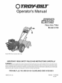 1
1
-
 2
2
-
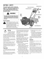 3
3
-
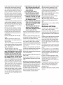 4
4
-
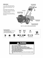 5
5
-
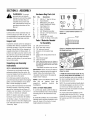 6
6
-
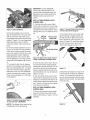 7
7
-
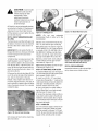 8
8
-
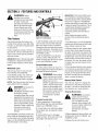 9
9
-
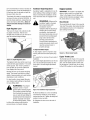 10
10
-
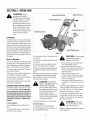 11
11
-
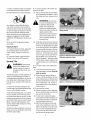 12
12
-
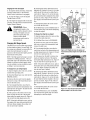 13
13
-
 14
14
-
 15
15
-
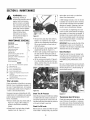 16
16
-
 17
17
-
 18
18
-
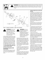 19
19
-
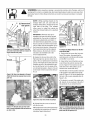 20
20
-
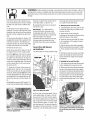 21
21
-
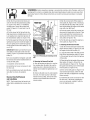 22
22
-
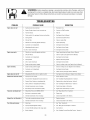 23
23
-
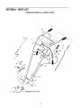 24
24
-
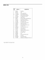 25
25
-
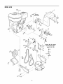 26
26
-
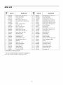 27
27
-
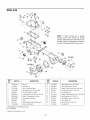 28
28
-
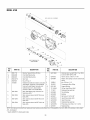 29
29
-
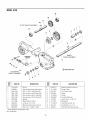 30
30
-
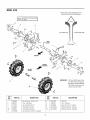 31
31
-
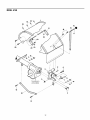 32
32
-
 33
33
-
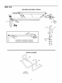 34
34
-
 35
35
-
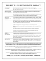 36
36


Troy-Bilt 21A-675B766 User manual
- Category
- Mini tillers
- Type
- User manual
Ask a question and I''ll find the answer in the document
Finding information in a document is now easier with AI
Related papers
-
Troy-Bilt 665B Owner's manual
-
-
-
-
-
-
-
-
-
Troy-Bilt E666M-Pony ES User manual
Other documents
-
ACE 21C-65M1066 Owner's manual
-
Troybilt 12194 Owner's manual
-
-
Bolens 12229 User manual
-
-
-
Craftsman 987293190 Owner's manual
-
Ariens 926045 Installation guide
-
-
Husqvarna TS200FR User manual