
(FOR MODELS MANUFACTURED SINCE 10/10)

K_`jdXelXcgifm`[\jZi`k`ZXcjX]\kp`ejkilZk`fejfek_\gifg\ij\klg#
fg\iXk`fe#dX`ek\eXeZ\#Xe[j\im`Z\f]k_`jdXZ_`e\&kffc%JXm\k_`j
[fZld\ek#i\]\ikf`kf]k\e#Xe[lj\`kkf`ejkilZkfk_\ifg\iXkfij%
=X`cli\kfi\X[#le[\ijkXe[Xe[]fccfnk_\`ejkilZk`fej`ek_`jdXelXc
dXpi\jlck`e]`i\fij\i`fljg\ijfeXc`ealipÇ`eZcl[`e^XdglkXk`fe#
\c\ZkifZlk`fe#fi[\Xk_%
K_\fne\if]k_`jdXZ_`e\&kffc`jjfc\cpi\jgfej`Yc\]fi`kjjX]\lj\%
K_`ji\jgfej`Y`c`kp`eZcl[\jYlk`jefkc`d`k\[kfgifg\i`ejkXccXk`fe`e
XjX]\\em`ifed\ek#g\ijfee\ckiX`e`e^Xe[ljX^\Xlk_fi`qXk`fe#
gifg\i`ejg\Zk`feXe[dX`ek\eXeZ\#dXelXcXmX`cXY`c`kpXe[Zfdgi\$
_\ej`fe#Xggc`ZXk`fef]jX]\kp[\m`Z\j#Zlkk`e^&jXe[`e^&^i`e[`e^kffc
`ek\^i`kp#Xe[k_\ljX^\f]g\ijfeXcgifk\Zk`m\\hl`gd\ek%
K_\dXel]XZkli\in`ccefkY\_\c[c`XYc\]fi`ealipfigifg\ikp
[XdX^\]ifde\^c`^\eZ\#`dgifg\ikiX`e`e^#dXZ_`e\df[`]`ZXk`fejfi
d`jlj\%
Jfd\[ljkZi\Xk\[Ypgfn\ijXe[`e^#jXn`e^#^i`e[`e^#[i`cc`e^#Xe[
fk_\iZfejkilZk`feXZk`m`k`\jZfekX`ejZ_\d`ZXcjbefnekfk_\JkXk\f]
:Xc`]fie`XkfZXlj\ZXeZ\i#Y`ik_[\]\Zkjfifk_\ii\gif[lZk`m\_Xid%
Jfd\\oXdgc\jf]k_\j\Z_\d`ZXcjXi\1
C\X[]ifdc\X[$YXj\[gX`ekj%
:ipjkXcc`e\j`c`ZX]ifdYi`Zbj#Z\d\ekXe[fk_\idXjfeipgif[lZkj%
8ij\e`ZXe[Z_ifd`ld]ifdZ_\d`ZXccp$ki\Xk\[cldY\i%
Pflii`jb]ifdk_\j\\ogfjli\jmXi`\j#[\g\e[`e^fe_fnf]k\epfl
[fk_`jkpg\f]nfib%Kfi\[lZ\pfli\ogfjli\kfk_\j\Z_\d`ZXcj1
Nfib`eXn\ccm\ek`cXk\[Xi\X#Xe[nfibn`k_Xggifm\[jX]\kp\hl`g$
d\ek#jlZ_Xjk_fj\[ljkdXjbjk_XkXi\jg\Z`Xccp[\j`^e\[kf]`ck\i
flkd`ZifjZfg`ZgXik`Zc\j%

SET UPELECTRICAL MAINTENANCE
SERVICE PARTS
OPERATIONS
SAFETYINTRODUCTION
USE THE QUICK GUIDE PAGE LABELS TO SEARCH OUT INFORMATION FAST!
INTRODUCTION .....................................2
Woodstock Technical Support .................. 2
Machine Description ............................. 2
Machine Specifications .......................... 3
Controls and Features ........................... 5
SAFETY ...............................................6
Standard Machinery Safety Instructions ...... 6
Additional Safety for Disc Sanders ............ 8
ELECTRICAL .........................................9
Circuit Requirements ............................ 9
Grounding Requirements ...................... 10
Extension Cords ................................ 10
SETUP .............................................. 11
Unpacking ....................................... 11
Inventory ........................................ 11
Machine Placement ............................ 12
Cleaning Machine ............................... 13
Assembly ......................................... 14
Test Run .......................................... 16
OPERATIONS....................................... 17
Operation Overview ........................... 17
Attaching Sandpaper ........................... 18
Disc Sanding ..................................... 19
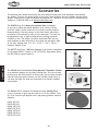
ACCESSORIES ...................................... 20
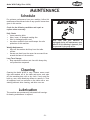
MAINTENANCE .................................... 21
Schedule ......................................... 21
Cleaning ......................................... 21
Lubrication ...................................... 21
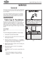
SERVICE ............................................ 22
General .......................................... 22
Table Gap & Parallelism ....................... 22
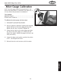
Miter Gauge Calibration ....................... 23
Table Tilt Calibration .......................... 24
Electrical Safety Instructions ................. 25
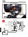
Wiring Diagram ................................. 26
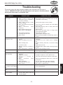
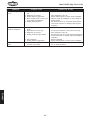
Troubleshooting ................................. 27
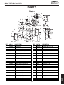
PARTS .............................................. 29
Main .............................................. 29
Machine Labels ................................. 30
WARRANTY ........................................ 33
Contents

-2-
Model W1815 (Mfg. Since 10/10)
INTRODUCTION
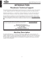
Woodstock Technical Support
This machine has been specially designed to provide many years of trouble-free service. Close attention
to detail, ruggedly built parts and a rigid quality control program assure safe and reliable operation.
Woodstock International, Inc. is committed to customer satisfaction. Our intent with this manual is to
include the basic information for safety, setup, operation, maintenance, and service of this product.
We stand behind our machines! In the event that questions arise about your machine, please contact
Woodstock International Technical Support at (360) 734-3482 or send e-mail to: tech-support@shopfox.
biz. Our knowledgeable staff will help you troubleshoot problems and process warranty claims.
INTRODUCTION
If you need the latest edition of this manual, you can download it from http://www.shopfox.biz.
If you have comments about this manual, please contact us at:
Woodstock International, Inc.
Attn: Technical Documentation Manager
P.O. Box 2309
Bellingham, WA 98227
Email: manuals@woodstockint.com
The Model W1815 features a 1
1
⁄2 HP, 220V, 1725 RPM motor equipped with a motor brake and a 15"
diameter sanding disc. Includes a miter gauge and a sanding table with X and Y miter slots that make it
possible to sand at virtually any angle with precision and control. Includes a built in 2
1
⁄2" OD dust port.
The steel powder-coated cabinet serves as a solid platform for sanding, and has shelves that provide
storage for extra sanding discs.
Machine Description

-3-
Model W1815 (Mfg. Since 10/10)
INTRODUCTION
© Woodstock International, Inc. • Phone #: (360) 734-3482 • Web: www.shopfox.biz
B68=>C:
HE:8>;>86I>DCH
<c\Zki`ZXc
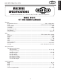
Required Power Source ............................................................................... 220V, 1-Phase, 60 Hz
Switch ....................................................................................... Paddle Switch w/Disabling Key
Switch Voltage .............................................................................................................220V
Cord Length ................................................................................................................. 6 ft.
Cord Gauge ..............................................................................................................14 AWG
Minimum Circuit Size ....................................................................................................... 15A
Plug Included ................................................................................................................. Yes
Included Plug Type ................................................................................................. NEMA 6-15
Dfkfi
Type ........................................................................................... TEFC Capacitor Start w/Brake
Horsepower .............................................................................................................. 1
1
⁄2 HP
Voltage ...................................................................................................................... 220V
Phase ....................................................................................................................... Single
Amps .......................................................................................................................... 12A
Speed .................................................................................................................. 1725 RPM
Cycle ........................................................................................................................ 60 Hz
Number Of Speeds ............................................................................................................. 1
Power Transfer .................................................................................................... Direct Drive
Bearings ................................................................................... Sealed, Permanently Lubricated
DX`eJg\Z`]`ZXk`fej
KXYc\;`jZJg\Z`]`ZXk`fej
Table Tilt Range ........................................................................................... +15° to -45°
Sanding Disc Diameter ................................................................................................ 15"
Sanding Disc Speed............................................................................................ 1725 RPM
Disc Table Length ..................................................................................................... 20"
Disc Table Width ....................................................................................................... 12"
Disc Table Thickness .................................................................................................
9
⁄16"
Miter Gauge Slot Width ..............................................................................................
3
⁄4"
Miter Gauge Slot Height .............................................................................................
5
⁄16"
Floor to Table Height ................................................................................................. 37"
Fm\iXcc;`d\ej`fej
Weight .................................................................................................................. 201 lbs.
Length ...................................................................................................................... 20
1
⁄2"
Width .......................................................................................................................... 26"
Height ......................................................................................................................... 46"
Foot Print (Length/Width) ........................................................................................ 20
1
⁄2" x 26"
BD9:AL&-&*
&*9>H8H6C9:Gl$7G6@:
Df[\cN(/(,DXZ_`e\Jg\Z`]`ZXk`fej#GX^\(f])

-4-
Model W1815 (Mfg. Since 10/10)
INTRODUCTION
J_`gg`e^;`d\ej`fej
:Xikfe(
Type ..............................................................................................................Carboard
Content ...........................................................................................................Machine
Weight............................................................................................................. 149 lbs.
Length ................................................................................................................... 25"
Width .................................................................................................................... 22"
Height ................................................................................................................... 20"
:Xikfe)
Type ..............................................................................................................Carboard
Content ....................................................................................................Cabinet Stand
Weight...............................................................................................................72 lbs.
Length ................................................................................................................... 29"
Width .................................................................................................................... 23"
Height ................................................................................................................... 11"
:fejkilZk`feDXk\i`Xcj
Base ..........................................................................................................................Steel
Disc ...................................................................................................................... Cast Iron
Miter Gauge ...........................................................................................................Aluminum
Cabinet Stand ..............................................................................................................Steel
Table .............................................................................................. Precision Ground Cast Iron
Paint ............................................................................................................ Powder Coated
Fk_\i
Number of Dust Ports ......................................................................................................... 1
Dust Port Size .............................................................................................................. 2
1
⁄2"
Customer Cleaning and Setup Time ........................................................... Approximately 30 Minutes
Made in ISO 9001 Factory .................................................................................................. Ye s
Warranty .................................................................................................................. 2 Year
Country of Origin ....................................................................................................... Taiwan
Serial Number Location .................................................................................ID Label on Cabinet
Sound Rating ............................................................................................................... 75 dB
=\Xkli\j
Automatic Internal Motor Braking System
Table Tilt Range -15° to +45°
Accepts 15" PSA Discs
Large Tilting Precision-Ground Cast Iron Table
X and Y-Axis Miter Slots
Steel Base
Df[\cN(/(,DXZ_`e\Jg\Z`]`ZXk`fej#GX^\)f])

-5-
Model W1815 (Mfg. Since 10/10)
INTRODUCTION
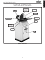
Controls and Features
Figure 1. Identification.
Motor
Disc Guard
Cabinet
Door
Work Table
Miter Gauge
Lock Handle
(One of Two)
Cast Iron Disc
(Sanding Disc
Attached)
Tilt Scale
On/Off Switch

-6-
Model W1815 (Mfg. Since 10/10)
SAFETY
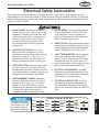
@e[`ZXk\jXgfk\ek`Xccp_XqXi[fljj`klXk`fen_`Z_#`]efkXmf`[\[#
D8Pi\jlck`ed`efifidf[\iXk\`ealip%
@e[`ZXk\jXe`dd`e\ekcp_XqXi[fljj`klXk`fen_`Z_#`]efkXmf`[\[#
N@CCi\jlck`e[\Xk_fij\i`flj`ealip%
@e[`ZXk\jXgfk\ek`Xccp_XqXi[fljj`klXk`fen_`Z_#`]efkXmf`[\[#
:FLC;i\jlck`e[\Xk_fij\i`flj`ealip%
K_`jjpdYfc`jlj\[kfXc\ikk_\lj\ikflj\]lc`e]fidXk`feXYflk
gifg\ifg\iXk`fef]k_\\hl`gd\ek#Xe[&fiXj`klXk`fek_XkdXp
ZXlj\[XdX^\kfk_\dXZ_`e\ip%
EFK@:<
J8=<KP
FNE<IËJD8EL8C% Read and understand this
owner’s manual BEFORE using machine.
Untrained users can be seriously hurt.
<P<GIFK<:K@FE% Always wear ANSI-approved
safety glasses or a face shield when operating
or observing machinery to reduce the risk of
eye injury or blindness from flying particles.
Everyday eyeglasses are not approved safety
glasses.
?8Q8I;FLJ;LJK% Dust created while using
machinery may cause cancer, birth defects,
or long-term respiratory damage. Be aware
of dust hazards associated with workpiece
materials, and always wear a NIOSH-approved
respirator to reduce your risk.
N<8I@E>GIFG<I8GG8I<C% Do not wear
clothing, apparel, or jewelry that can become
entangled in moving parts. Always tie back
or cover long hair. Wear non-slip footwear to
avoid accidental slips which could cause a loss
of workpiece control.
?<8I@E>GIFK<:K@FE% Always wear hearing
protection when operating or observing
loud machinery. Extended exposure to this
noise without hearing protection can cause
permanent hearing loss.
D<EK8C8C<IKE<JJ% Be mentally alert when
running machinery. Never operate under the
influence of drugs or alcohol, when tired, or
when distracted.
;@J:FEE<:K@E>GFN<IJLGGCP% Always
disconnect machine from power supply before
servicing, adjusting, or changing cutting tools
(bits, blades, cutters, etc.). Make sure switch
is in OFF position before reconnecting to avoid
an unexpected or unintentional start.
;8E><IFLJ<EM@IFED<EKJ% Do not use
machinery in wet or rainy locations, cluttered
areas, around flammables, or in poorly-lit
areas. Keep work area clean, dry, and well-
lighted to minimize risk of injury.
JkXe[Xi[DXZ_`e\ipJX]\kp@ejkilZk`fej
For Your Own Safety,
Read Manual Before Operating Machine
K_\ gligfj\ f] jX]\kp jpdYfcj `j kf XkkiXZk pfli Xkk\ek`fe kf gfjj`Yc\ _XqXi[flj Zfe[`k`fej% K_`j
dXelXclj\jXj\i`\jf]jpdYfcjXe[j`^eXcnfi[j`ek\e[\[kfZfem\pk_\c\m\cf]`dgfikXeZ\f]k_\
jX]\kpd\jjX^\j%K_\gif^i\jj`fef]jpdYfcj`j[\jZi`Y\[Y\cfn%I\d\dY\ik_XkjX]\kpd\jjX^\jYp
k_\dj\cm\j[fefk \c`d`eXk\ [Xe^\i Xe[Xi\efkXjlYjk`klk\]figifg\iXZZ`[\ekgi\m\ek`fe d\X$
jli\jÇk_`ji\jgfej`Y`c`kp`jlck`dXk\cplgkfk_\fg\iXkfi
SAFETY
Standard Machinery Safety Instructions

-7-
Model W1815 (Mfg. Since 10/10)
SAFETY
8GGIFM<;FG<I8K@FE% Untrained operators
can be seriously hurt by machinery. Only
allow trained or properly supervised people
to use machine. When machine is not being
used, disconnect power, remove switch keys,
or lock-out machine to prevent unauthorized
use—especially around children. Make
workshop kid proof!
FECPLJ<8J@EK<E;<;% Only use machine for
its intended purpose. Never modify or alter
machine for a purpose not intended by the
manufacturer or serious injury may result!
LJ<I<:FDD<E;<;8::<JJFI@<J% Consult
this owner’s manual or the manufacturer for
recommended accessories. Using improper
accessories will increase the risk of serious
injury.
:?@C;I<E9PJK8E;<IJ% Keep children and
bystanders a safe distance away from work
area. Stop using machine if children or
bystanders become a distraction.
I<DFM<8;ALJK@E>KFFCJ% Never leave
adjustment tools, chuck keys, wrenches, etc.
in or on machine—especially near moving
parts. Verify removal before starting!
J<:LI@E>NFIBG@<:<% When required, use
clamps or vises to secure workpiece. A secured
workpiece protects hands and frees both of
them to operate the machine.
=<<;;@I<:K@FE% Unless otherwise noted, feed
work against the rotation of blades or cutters.
Feeding in the same direction of rotation may
pull your hand into the cut.
>L8I;J:FM<IJ% Guards and covers can
protect you from accidental contact with
moving parts or flying debris. Make sure
they are properly installed, undamaged, and
working correctly before using machine.
E<M<IJK8E;FED8:?@E<% Serious injury or
accidental contact with cutting tool may
occur if machine is tipped. Machine may be
damaged.
JK89C<D8:?@E<% Unexpected movement during
operations greatly increases the risk of injury
and loss of control. Verify machines are
stable/secure and mobile bases (if used) are
locked before starting.
=FI:@E>D8:?@E<IP% Do not force machine. It
will do the job safer and better at the rate for
which it was designed.
8NBN8I;GFJ@K@FEJ% Keep proper footing and
balance at all times when operating machine.
Do not overreach! Avoid awkward hand
positions that make workpiece control difficult
or increase the risk of accidental injury.
LE8KK<E;<;FG<I8K@FE% Never leave machine
running while unattended. Turn machine off
and ensure all moving parts completely stop
before walking away.
D8@EK8@EN@K?:8I<% Follow all maintenance
instructions and lubrication schedules to
keep machine in good working condition. An
improperly maintained machine may increase
the risk of serious injury.
:?<:B;8D8><;G8IKJ% Regularly inspect
machine for damaged parts, loose bolts,
mis-adjusted or mis-aligned parts, binding,
or any other conditions that may affect safe
operation. Always repair or replace damaged
parts, wires, cords, or plugs before operating
machine.
D8@EK8@EGFN<I:FI;J%When disconnecting
cord-connected machines from power, grab
and pull the plug—NOT the cord. Pulling the
cord may damage the wires inside. Do not
handle the cord/plug with wet hands. Avoid
cord damage by keeping it away from heated
surfaces, high traffic areas, harsh chemicals,
and wet or damp locations.
<OG<I@<E:@E>;@==@:LCK@<J% If at any time you
are experiencing difficulties performing the
intended operation, stop using the machine!
Contact our Technical Support for help at
(360) 734-3482.

-8-
Model W1815 (Mfg. Since 10/10)
SAFETY
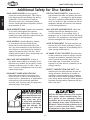
Additional Safety for Disc Sanders
READ and understand this
entire manual before using
this machine. Serious per-
sonal injury may occur
if safety and operational
information is not under-
stood and followed. DO
NOT risk your safety by
not reading!
USE this and other machinery with caution
and respect. Always consider safety first,
as it applies to your individual working
conditions. No list of safety guidelines can
be complete—every shop environment is
different. Failure to follow guidelines could
result in serious personal injury, damage
to equipment or poor work results.
AVOID FINGER INJURIES. Never purposely
touch the moving sanding disc. Take care to
keep fingers away from sanding disc during
operations. If the workpiece is small or
difficult to hold, use a workpiece holding
fixture. Sanding abrasives can quickly remove
large amounts of skin!
AVOID WORKPIECE GRAB. Support the workpiece
on the work table against the rotation
direction of the sanding disc. Otherwise, the
sanding disc could grab the workpiece and pull
your hands into the moving disc.
AVOID KICKBACK. Avoid kickback by sanding
in accordance with directional arrows.
Always sand on the downward side of the
disc—pay close attention to the direction of
disc rotation to avoid placing the workpiece
against the upward side of the disc. Avoid
sanding with excessive force. Always keep the
sanding disc guard installed.
ONLY SAND SAFE WORKPIECES. If there is
any doubt about stability or integrity of the
material to be sanded, do not sand it. Never
attempt to sand any sort of cable, chain, or
wire. If you do, entanglement can occur and
cause serious injury.
DISCONNECT POWER WHEN SERVICING.
Disconnect the machine from power and
allow the disc to come to a complete stop
before service, maintenance, or adjustments.
Avoid pulling cord-connected machinery
from the cord—instead, grasp the plug when
disconnecting it from power.
POSITION TABLE CORRECTLY. Make sure the
gap between the table and sanding disc does
not exceed
3
⁄16"—too large of a gap increases
the risk of workpiece grab and pinch injuries,
while too small of a gap increases the risk of
sandpaper damage and restricts the removal
of dust during operation.
ONLY USE SAFE SANDPAPER DISCS. Never use
sanding discs that are damaged or torn;
or if the adhesive is not sticking firmly. If
sandpaper rips or comes off of the disc during
operation, the workpiece or your hands could
become entangled with the moving disc.
AVOID ENTANGLEMENT. Tie back long hair and
remove any loose-fitting clothing or jewelry
that could be caught up in the sanding disc or
other moving machine parts.
BE AWARE OF DUST ALLERGIES. Be aware that
certain woods may cause an allergic reaction
in people and animals, especially when fine
dust is created by sanding. Make sure you
know what type of wood dust you will be
exposed to in case there is a possibility of an
allergic reaction.
PROTECT YOURSELF FROM FINE DUST. This
machine puts fine dust particles into the air
during operation. Wood dust is harmful to
respiratory systems and long term exposure
may lead to severe health problems. Reduce
your risk by always wearing a NIOSH-approved
respirator during machine operation and for a
short time after.

-9-
Model W1815 (Mfg. Since 10/10)
ELECTRICAL
ELECTRICAL
Circuit Requirements
This machine must be connected to the correct size and
type of power supply circuit, or fire or electrical damage
may occur. Read through this section to determine if an
adequate power supply circuit is available. If a correct
circuit is not available, a qualified electrician MUST install
one before you can connect the machine to power.
A power supply circuit includes all electrical equipment
between the breaker box or fuse panel in the building
and the machine. The power supply circuit used for
this machine must be sized to safely handle the full-
load current drawn from the machine for an extended
period of time. (If this machine is connected to a circuit
protected by fuses, use a time delay fuse marked D.)
Circuit Requirements
This machine is prewired to operate on a 220V power
supply circuit that has a verified ground and meets the
following requirements:
Circuit Type ............ 220V/240V, 60 Hz, Single-Phase
Circuit Size ............................................ 15 Amps
Plug/Receptacle ................................... NEMA 6-15
Full-Load Current Rating
The full-load current rating is the amperage a machine
draws at 100% of the rated output power. On machines
with multiple motors, this is the amperage drawn by the
largest motor or sum of all motors and electrical devices
that might operate at one time during normal operations.
Full-Load Current Rating at 220V ................ 12 Amps
K_\ dXZ_`e\ dljk Y\ gifg\icp j\k lg
Y\]fi\ `k `j jX]\ kf fg\iXk\% ;F EFK
Zfee\Zk k_`j dXZ_`e\ kf k_\ gfn\i
jfliZ\ lek`c `ejkilZk\[ kf [f cXk\i `e
k_`jdXelXc%
@eZfii\Zkcp n`i`e^ fi ^ifle[`e^ k_`j
dXZ_`e\ZXeZXlj\\c\ZkifZlk`fe#]`i\#
fidXZ_`e\[XdX^\%Kfi\[lZ\k_`ji`jb#
fecp X hlXc`]`\[ \c\Zki`Z`Xe fi j\im`Z\
g\ijfee\c j_flc[ [f Xep i\hl`i\[
\c\Zki`ZXcnfib]fik_`jdXZ_`e\%
EFK@:<
K_\Z`iZl`ki\hl`i\d\ekjc`jk\[ `e k_`j
dXelXc Xggcp kf X [\[`ZXk\[ Z`iZl`kÇ
n_\i\fecpfe\dXZ_`e\n`ccY\ilee`e^
Xk X k`d\% @] k_`j dXZ_`e\ n`cc Y\
Zfee\Zk\[ kf X j_Xi\[ Z`iZl`k n_\i\
dlck`gc\ dXZ_`e\j n`cc Y\ ilee`e^ Xk
k_\ jXd\ k`d\# Zfejlck X hlXc`]`\[
\c\Zki`Z`Xekf\ejli\k_Xkk_\Z`iZl`k`j
gifg\icpj`q\[]fijX]\fg\iXk`fe%

-10-
Model W1815 (Mfg. Since 10/10)
ELECTRICAL
Grounding Requirements
This machine MUST be grounded. In the event of certain
types of malfunctions or breakdowns, grounding provides
a path of least resistance for electric current to travel—in
order to reduce the risk of electric shock.
Improper connection of the equipment-grounding wire will
increase the risk of electric shock. The wire with green
insulation (with/without yellow stripes) is the equipment-
grounding wire. If repair or replacement of the power
cord or plug is necessary, do not connect the equipment-
grounding wire to a live (current carrying) terminal.
Check with a qualified electrician or service personnel
if you do not understand these grounding requirements,
or if you are in doubt about whether the tool is
properly grounded. If you ever notice that a cord or
plug is damaged or worn, disconnect it from power, and
immediately replace it with a new one.
Grounding Prong
Current Carrying Prongs
6-15 PLUG
GROUNDED
6-15 RECEPTACLE
220V
Figure 2. NEMA 6-15 plug & receptacle.
This machine is equipped with a power cord that has an
equipment-grounding wire and NE M A 6-15 grounding plug.
The plug must only be inserted into a matching receptacle
(see =`^li\) that is properly installed and grounded in
accordance with local codes and ordinances.
For 220V Connection
K_\ dXZ_`e\ dljk Y\ gifg\icp j\k lg
Y\]fi\ `k `j jX]\ kf fg\iXk\% ;F EFK
Zfee\Zk k_`j dXZ_`e\ kf k_\ gfn\i
jfliZ\ lek`c `ejkilZk\[ kf [f cXk\i `e
k_`jdXelXc%
Extension Cords
We do not recommend using an extension cord with this
machine. Extension cords cause voltage drop, which may
damage electrical components and shorten motor life.
Voltage drop increases with longer extension cords and
the gauge smaller gauge sizes (higher gauge numbers
indicate smaller sizes).
Any extension cord used with this machine must contain a
ground wire, match the required plug and receptacle, and
meet the following requirements:
Minimum Gauge Size at 220V ...................... 14 AWG
Maximum Length (Shorter is Better) ................50 ft.
NOTICE
No adapter is available or should
be used with this machine. If the
machine must be reconnected for
use on a different type of electric
circuit, the reconnection should be
made by qualified service personnel;
and after reconnection, the machine
must comply with all local codes and
ordinances.

-11-
Model W1815 (Mfg. Since 10/10)
SETUP
This machine has been carefully packaged for safe
transportation. If you notice the machine has been
damaged during shipping, please contact your authorized
Shop Fox dealer immediately.
Unpacking
SETUP
The following is a description of the main components
shipped with the Model W1815. Lay the components out
to inventory them.
Note: If you can't find an item on this list, check the
mounting location on the machine or examine the
packaging materials carefully. Occasionally we pre-install
certain components for safer shipping.
Main Inventory (Figure 3) Qty
A. Sander Assembly ...........................................1
B. Left Side Panel ............................................1
C. Right Side Panel ...........................................1
D. Upper Shelf 16
3
⁄4" x 15
3
⁄8" ..............................1
E. Lower Shelf 16" x 18
3
⁄8" ..................................1
F. Rear Panel ..................................................1
G. Panel and Door Assembly .................................1
H. Miter Gauge Assembly ....................................1
I. Wrench 10 x 13 ............................................1
J. Bolt Bag .....................................................1
—Flat Washers
5
⁄16" ........................................4
—Hex Bolts M8-1.25 x 45 .................................4
—Hex Nuts
3
⁄8"-16 .........................................4
—Feet ........................................................4
—Flange Bolts M6-1 x 12 ..................................8
—Carriage Bolts
5
⁄16"-18 x
3
⁄4" ...........................8
—Flange Nuts
5
⁄16"-18 .....................................8
Inventory
A
J
I
H
B
C
D
E
F
G
Figure 3. Inventory.
Keep machine disconnected from
power until instructed otherwise.
Immediately discard all plastic bags
and packing materials to eliminate a
choking and suffocation hazard for
children and animals.

-12-
Model W1815 (Mfg. Since 10/10)
SETUP
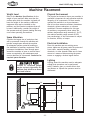
Figure 4. Model W1815 working clearances.
Machine Placement
Weight Load
Refer to the Machine Specifications for the
weight of your machine. Make sure that the
surface upon which the machine is placed will
bear the weight of the machine, additional
equipment that may be installed on the
machine, and the heaviest workpiece that will
be used. Additionally, consider the weight of
the operator and any dynamic loading that may
occur when operating the machine.
Space Allocation
Consider the largest size of workpiece that
will be processed through this machine and
provide enough space around the machine
for adequate operator material handling or
the installation of auxiliary equipment. With
permanent installations, leave enough space
around the machine to open or remove doors/
covers as required by the maintenance and
service described in this manual. See below for
required space allocation.
Physical Environment
The physical environment where your machine is
operated is important for safe operation and the
longevity of its components. For best results,
operate this machine in a dry environment
that is free from excessive moisture, hazardous
chemicals, airborne abrasives, or extreme
conditions. Extreme conditions for this type
of machinery are generally those where the
ambient temperature range exceeds 41°–104°F;
the relative humidity range exceeds 20–95%
(non-condensing); or the environment is subject
to vibration, shocks, or bumps.
Electrical Installation
Place this machine near an existing power
source. Make sure all power cords are protected
from traffic, material handling, moisture,
chemicals, or other hazards. Make sure to leave
access to a means of disconnecting the power
source or engaging a lockout/tagout device.
Lighting
Lighting around the machine must be adequate
enough that operations can be performed
safely. Shadows, glare, or strobe effects that
may distract or impede the operator must be
eliminated.
Children or untrained people
may be seriously injured by this
machine. Only install in an access
restricted location.
26"
4"
20"
Minimum
7.5"
Wall

-13-
Model W1815 (Mfg. Since 10/10)
SETUP
To prevent corrosion during shipment and storage of your
machine, the factory has coated the bare metal surfaces
of your machine with a heavy-duty rust prevention
compound.
If you are unprepared or impatient, this compound can
be difficult to remove. To ensure that the removal of this
coating is as easy as possible, please gather the correct
cleaner, lubricant, and tools listed below:
• Cleaner/degreaser designed to remove storage wax
and grease
• Safetyglasses&disposablegloves
• Solvent brush or paint brush
• DisposableRags
To remove the rust preventative coating, do these
steps:
1. DISCONNECT THE MACHINE FROM POWER.
2. Put on safety glasses and disposable gloves.
3. Using a liberal amount of your cleaner/degreaser,
Coat all surfaces that have the coating, and let soak
for few minutes.
4. Wipe off the surfaces. If your cleaner/degreaser is
effective, the coating will wipe off easily.
Tip: To clean off thick coats of the rust preventative
compound on flat surfaces, use a PLASTIC paint
scraper to scrape off the majority of the coating
before wiping it off with your rag. (Do not use a
metal scraper or you may scratch your machine.)
5. Repeat the cleaning steps as necessary until all of
the compound is removed.
6. To prevent rust on the freshly cleaned surfaces,
immediately coat with a quality metal protectant.
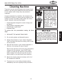
Gasoline and petroleum
products have low flash
points and can explode
or cause fire if used to
clean machinery. Avoid
using these products
to clean machinery.
Many cleaning solvents
are toxic if inhaled.
Minimize your risk
by only using these
products in a well
ventilated area.
NOTICE
In a pinch, automotive degreasers,
mineral spirits or WD•40 can be used
to remove rust preventative coating.
Before using these products, though,
test them on an inconspicuous area of
your paint to make sure they will not
damage it.
Cleaning Machine

-14-
Model W1815 (Mfg. Since 10/10)
SETUP
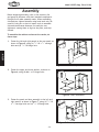
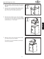
Figure 5. Side and rear panel installation.
Figure 7. Door w/panel installation.
Figure 6. Shelf installation.
Assembly
Before beginning assembly, refer to the inventory list
and group all fasteners with their intended components.
Doing this will make assembly easier. When assembling
this machine, tighten fasteners using hand tools only. Be
careful if using air or electric impact tools to assemble
this machine because fasteners can easily be over-
tightened, causing them to dig into the paint, and strip
threads
To assemble the cabinet and mount the sander, do
these steps:
1. Fasten the left and right panels to the rear panel, as
shown in Figure 5, using (4)
5
⁄16"-18 x
3
⁄4" carriage
bolts and (4)
5
⁄16"-18 flange nuts.
3. Fasten the panel and door assembly to the left and
right panels, as shown in Figure 7, using (4)
5
⁄16"-18
x
3
⁄4" carriage bolts and (4)
5
⁄16"-18 flange nuts.
2. Fasten the upper and lower shelves, as shown in
Figure 6, using (8) M6-1 x 12 flange bolts.

-15-
Model W1815 (Mfg. Since 10/10)
SETUP
Figure 9. Sander installation.
Figure 10. Fully assembled sander.
Figure 8. Foot installation.
7. Make sure that all tools and objects used for setup
are cleared away from the machine.
The machine is now fully assembled, and ready for
the test run procedure.
4. Invert the cabinet, thread the (4) hex nuts onto the
feet, and install the feet into the base, as shown in
Figure 8.
5. Adjust the feet to the same height, tighten the hex
nuts against the cabinet base to lock the feet in
place, then return the cabinet right side up.
6. With the help of another person, place the sanding
unit onto the top of the cabinet, as shown in Figure
9, and fasten it to the cabinet using (4) M8-1.25 x 45
hex bolts and (4)
5
⁄16" flat washers.

-16-
Model W1815 (Mfg. Since 10/10)
SETUP
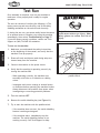
Figure 11. Removing switch key from
paddle switch.
Once assembly is complete, test run your machine to
make sure it runs properly and is ready for regular
operation.
The test run consists of verifying the following: 1) The
motor powers up and runs correctly, and 2) the safety
disabling mechanism on the switch works correctly.
If, during the test run, you cannot easily locate the source
of an unusual noise or vibration, stop using the machine
immediately, then review Troubleshooting on Page 27.
If you still cannot remedy a problem, contact our Tech
Support at (360) 734-3482 for assistance.
To test run the machine:
1. Make sure you understand the safety instructions
at the beginning of the manual, and verify that the
machine is set up properly.
2. Ensure all tools and objects used during setup are
cleared away from the machine.
3. Connect the machine to the power source.
4. Verify that the machine is operating correctly by
turning the machine ON.
— When operating correctly, the machine runs
smoothly with little or no vibration or rubbing
noises.
— Investigate and correct strange or unusual noises
or vibrations before operating the machine further.
Always disconnect the machine from power when
investigating or correcting potential problems.
5. Turn the machine OFF.
6. Remove the switch disabling key (see Figure 11).
7. Try to start the machine with the paddle switch.
— If the machine does not start, the switch disabling
feature is working as designed.
— If the machine starts, immediately stop the
machine. The switch disabling feature is not
working correctly. Call Tech Support for help.
Test Run
Projectiles thrown from the machine
could cause serious eye injury. Wear
safety glasses to reduce the risk of
injury.

-17-
Model W1815 (Mfg. Since 10/10)
OPERATIONS
OPERATIONS
READ and understand this entire instruc-
tion manual before using this machine.
Serious personal injury may occur if
safety and operational information is not
understood and followed. DO NOT risk
your safety by not reading!
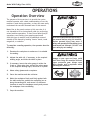
The purpose of this overview is to provide the novice
machine operator with a basic understanding of how the
machine is used during operation, so they can more easily
understand the controls discussed later in this manual.
Note: Due to the generic nature of this overview, it is
not intended to be an instructional guide for performing
actual machine operations. To learn more about specific
operations, seek training from people experienced
with this type of machine, and do additional research
outside of this manual by reading "how-to" books, trade
magazines, or websites.
To complete a sanding operation, the operator does the
following:
1. Examines the workpiece to make sure it is suitable
for sanding.
2. Adjusts the table tilt, if necessary, to the required
sanding angle, and locks the table in place.
3. If necessary, inserts the miter gauge in either the
X-axis or Y-axis miter slots, adjusts the miter gauge
to the required sanding angle, and locks it in place.
4. Wears safety glasses and a respirator.
5. Starts the machine and dust collector.
6. Holds the workpiece firmly and flatly against both
the table and miter, pushes the workpiece into or
along the sanding disc, and moves it to different
locations to wear the sandpaper evenly and prevent
the sandpaper from overheating.
7. Stops the machine.
Operation Overview
Damage to your eyes and lungs could
result from using this machine without
proper protective gear. Always wear
safety goggles and a respirator when
operating this machine.

-18-
Model W1815 (Mfg. Since 10/10)
OPERATIONS
The Model W1815 sander accepts 15" diameter adhesive-
backed sanding discs. These are available in a variety of
grits.
The sanding disc sticks to the surface of the cast iron
disc platen, using the pressure-sensitive adhesive backing
(PSA). The sandpaper can be replaced without removing
either the table or the dust port.
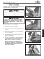
To attach sandpaper, do these steps:
1. DISCONNECT MACHINE FROM POWER!
2. Remove the safety guard, peel off the old sandpaper,
clean the disc surface with mineral spirits, and wipe
it dry.
3. Peel back the protective layer on one-half of the
sandpaper disc and fold it against the remaining
half.
4. Slip the half with the protective layer between the
disc and the table edge (see Figure 12).
5. Position the exposed adhesive on the upper half of
the disc that extends above the table. Once it is
positioned evenly across the disc, press the adhesive
onto the surface.
6. Rotate the disc so the lower half is above the table.
Peel off the other half of the protective paper, and
press the remaining sandpaper against the disc so
adhesion is complete.
7. Re-install the safety guard.
Attaching Sandpaper
Figure 12. Sandpaper being slipped
between the disc and table.
Page is loading ...
Page is loading ...
Page is loading ...
Page is loading ...
Page is loading ...
Page is loading ...
Page is loading ...
Page is loading ...
Page is loading ...
Page is loading ...
Page is loading ...
Page is loading ...
Page is loading ...
Page is loading ...
Page is loading ...
Page is loading ...
-
 1
1
-
 2
2
-
 3
3
-
 4
4
-
 5
5
-
 6
6
-
 7
7
-
 8
8
-
 9
9
-
 10
10
-
 11
11
-
 12
12
-
 13
13
-
 14
14
-
 15
15
-
 16
16
-
 17
17
-
 18
18
-
 19
19
-
 20
20
-
 21
21
-
 22
22
-
 23
23
-
 24
24
-
 25
25
-
 26
26
-
 27
27
-
 28
28
-
 29
29
-
 30
30
-
 31
31
-
 32
32
-
 33
33
-
 34
34
-
 35
35
-
 36
36


Ask a question and I''ll find the answer in the document
Finding information in a document is now easier with AI
Related papers
-
Woodstock W1741 Owner's manual
-
Woodstock W1741S Owner's manual
-
Shop fox 1 HP 800 CFM Dust Collector W1727 User manual
-
Grizzly G7297 Owner's manual
-
-
-
-
-
-
Other documents
-
-
-
-
-
-
Delta 31-140 Operating instructions
-
-
Woodstock W1830 User manual
-
-
RIDGID R2601 User manual