Gigabyte GA-X58A-OC Owner's manual

Category
Motherboards
Type
Owner's manual
GA-X58A-OC
User's Manual
Rev. 1001
12ME-X58AOC-1001R
Motherboard
GA-X58A-OC
Mar. 22, 2011
Mar. 22, 2011
Motherboard
GA-X58A-OC
Copyright
© 2011 GIGA-BYTE TECHNOLOGY CO., LTD. All rights reserved.
The trademarks mentioned in this manual are legally registered to their respective owners.
Disclaimer
Information in this manual is protected by copyright laws and is the property of GIGABYTE.
Changes to the specifications and features in this manual may be made by GIGABYTE
without prior notice. No part of this manual may be reproduced, copied, translated, transmitted,
or published in any form or by any means without GIGABYTE's prior written permission.
Documentation Classications
In order to assist in the use of this product, GIGABYTE provides the following types of documentations:
For quick set-up of the product, read the Quick Installation Guide included with the product.
For detailed product information, carefully read the User's Manual.
For product-related information, check on our website at:
http://www.gigabyte.com
Identifying Your Motherboard Revision
The revision number on your motherboard looks like this: "REV: X.X." For example, "REV: 1.0"
means the revision of the motherboard is 1.0. Check your motherboard revision before updating
motherboard BIOS, drivers, or when looking for technical information.
Example:
- 4 -
Table of Contents
Box Contents ...................................................................................................................6
Optional Items .................................................................................................................6
GA-X58A-OC Motherboard Layout ..................................................................................7
GA-X58A-OC Motherboard Block Diagram .....................................................................8
Chapter 1 Hardware Installation .....................................................................................9
1-1 Installation Precautions .................................................................................... 9
1-2 ProductSpecications .................................................................................... 10
1-3 Installing the CPU and CPU Cooler ............................................................... 13
1-3-1 Installing the CPU ...................................................................................................13
1-3-2 Installing the CPU Cooler .......................................................................................15
1-4 Installing the Memory ..................................................................................... 16
1-4-1 Dual/3ChannelMemoryConguration ..................................................................16
1-4-2 Installing a Memory ...............................................................................................17
1-5 Installing an Expansion Card ......................................................................... 18
1-6 Setup of ATI CrossFireX
/NVIDIASLIConguration ..................................... 19
1-7 Back Panel Connectors .................................................................................. 21
1-8 Onboard Buttons, Switches, and LEDs .......................................................... 22
1-9 Internal Connectors ........................................................................................ 25
Chapter 2 BIOS Setup ..................................................................................................33
2-1 Startup Screen ............................................................................................... 34
2-2 The Main Menu .............................................................................................. 35
2-3 MB Intelligent Tweaker(M.I.T.) ........................................................................ 37
2-4 Standard CMOS Features .............................................................................. 47
2-5 Advanced BIOS Features .............................................................................. 49
2-6 Integrated Peripherals .................................................................................... 51
2-7 Power Management Setup ............................................................................. 54
2-8 PC Health Status ............................................................................................ 56
2-9 Load Fail-Safe Defaults .................................................................................. 58
2-10 Load Optimized Defaults ................................................................................ 58
2-11 Set Supervisor/User Password ...................................................................... 59
2-12 Save & Exit Setup .......................................................................................... 60
2-13 Exit Without Saving ........................................................................................ 60
- 5 -
Chapter 3 Drivers Installation ........................................................................................61
3-1 Installing Chipset Drivers ............................................................................... 61
3-2 Application Software ...................................................................................... 62
3-3 Technical Manuals .......................................................................................... 62
3-4 Contact ........................................................................................................... 63
3-5 System ........................................................................................................... 63
3-6 Download Center ........................................................................................... 64
3-7 New Utilities ................................................................................................... 64
Chapter 4 Unique Features ...........................................................................................65
4-1 Xpress Recovery2 .......................................................................................... 65
4-2 BIOS Update Utilities ..................................................................................... 68
4-2-1 Updating the BIOS with the Q-Flash Utility .............................................................68
4-2-2 Updating the BIOS with the @BIOS Utility .............................................................71
4-3 EasyTune 6 .................................................................................................... 72
4-4 Q-Share .......................................................................................................... 73
4-5 Smart 6
....................................................................................................... 74
4-6 Auto Green ..................................................................................................... 78
4-7 eXtreme Hard Drive (X.H.D) .......................................................................... 79
4-8 Cloud OC ....................................................................................................... 80
Chapter 5 Appendix ......................................................................................................81
5-1 ConguringSATAHardDrive(s) ..................................................................... 81
5-1-1 ConguringIntelICH10RSATAControllers ...........................................................81
5-1-2 ConguringMarvell88SE9182SATAController .....................................................89
5-1-3 Installing the SATA RAID/AHCI Driver and Operating System ...............................95
5-2 ConguringAudioInputandOutput ............................................................. 104
5-2-1 Conguring2/4/5.1/7.1-ChannelAudio .................................................................104
5-2-2 ConguringMicrophoneRecording ......................................................................106
5-2-3 Using the Sound Recorder ...................................................................................108
5-3 Troubleshooting............................................................................................ 109
5-3-1 Frequently Asked Questions ................................................................................109
5-3-2 Troubleshooting Procedure ..................................................................................110
5-4 POST Error Code ......................................................................................... 112
- 6 -
Box Contents
GA-X58A-OC motherboard
Motherboard driver disk
User's Manual
Quick Installation Guide
Four SATA cables
I/O Shield
One 2-Way SLI bridge connector
One 3-Way SLI bridge connector
One 2-Way CrossFireX bridge connector
Seven voltage measurement cables
Optional Items
2-port USB 2.0 bracket (Part No. 12CR1-1UB030-5*R)
2-port SATA power cable (Part No. 12CF1-2SERPW-0*R)
The box contents above are for reference only and the actual items shall depend on the product package you obtain.
The box contents are subject to change without notice.
The motherboard image is for reference only.
- 7 -
GA-X58A-OC Motherboard Layout
(Note) For error code information, please refer to Chapter 5.
1
DIP
1 2 3
KB_MS
LGA1366
ATX
GA-X58A-OC
AUDIO
B_BIOS
PCIEX8_1
DDR3_2
DDR3_3
DDR3_1
BAT
F_PANEL
ATX_12V_2X
Intel
®
X58
Intel
®
ICH10R
SATA2_1
SATA2_3
SATA2_5
ATX4P4
SATA2_0
SATA2_2
SATA2_4
F_AUDIO
M_BIOS
USB_LAN
PCIEX16_1
SPDIF_O
SYS_FAN3
SYS_FAN4
GSATA3_7
GSATA3_6
DDR3_4
Marvell
88SE9182
PCIEX16_2
PCI
R_USB3
SW4
iTE IT8720
F_USB1
HP_PWR1
CPU_FAN
ATX_12V_2X1
Realtek
RTL8111E
Etron
EJ168
NB_FAN
PCIEX8_2
HP_PWR
ATX4P1
DDR3_5
DDR3_6
Debug LED
(Note)
SYS_FAN1
CMOS_SW
RST_SW
PW_SW
RATIO_UP
RATIO_DW
FREQ_UP
FREQ_DW
Gear
4G
SYS_FAN6
SYS_FAN5
SW1
SYS_FAN2
J1 VCORE
J2 QPIVTT
J3 VDIMM
J4 DDR_VTT
J6 CPU_PLL
J7 VMCH_CORE
J5 QPI_PLL
_
+
_
+
MBIOS_LED
BBIOS_LED
SYSTEM1 Temperature Sensor
MCH Temperature
Sensor
SYSTEM2 Temperature Sensor
CODEC
- 8 -
GA-X58A-OC Motherboard Block Diagram
PS/2 KB/Mouse
LGA1366
CPU
QPI
Interface
Intel
®
X58
IOH CLK (133 MHz)
Intel
®
ICH10R
IT8720
CPU CLK+/- (133 MHz)
6 SATA 3Gb/s
Dual BIOS
4 USB 2.0/1.1
LPC
Bus
DDR3 2200/1333/1066/800 MHz
PCI Express Bus
PCI Express Bus
Dual/3 Channel Memory
PCIe CLK
(100 MHz)
PCIe CLK
(100 MHz)
x2
x1
LAN
RJ45
Realtek RTL8111E
Marvell
88SE9182
2 SATA 6Gb/s
PCI Bus
1 PCI
PCI CLK
(33 MHz)
PCI Express Bus
x1
Etron
EJ168
2 USB 3.0/2.0
PCI Bus
CODEC
Line In (Rear Speaker Out )
Line Out (Front Speaker Out )
MIC (Center/Subwoofer Speaker Out )
PCIe CLK
(100 MHz)
1 PCI Express x16
2 PCI Express x8
x8
x16
1 PCI Express x16
x16
Switch
2 PCI Express x8
x8
Switch
- 9 - Hardware Installation
1-1 Installation Precautions
The motherboard contains numerous delicate electronic circuits and components which can
become damaged as a result of electrostatic discharge (ESD). Prior to installation, carefully read
the user's manual and follow these procedures:
• Prior to installation, do not remove or break motherboard S/N (Serial Number) sticker or
warranty sticker provided by your dealer. These stickers are required for warranty validation.
• Always remove the AC power by unplugging the power cord from the power outlet before
installing or removing the motherboard or other hardware components.
• When connecting hardware components to the internal connectors on the motherboard,
make sure they are connected tightly and securely.
• When handling the motherboard, avoid touching any metal leads or connectors.
• It is best to wear an electrostatic discharge (ESD) wrist strap when handling electronic com-
ponents such as a motherboard, CPU or memory. If you do not have an ESD wrist strap,
keepyourhandsdryandrsttouchametalobjecttoeliminatestaticelectricity.
Prior to installing the motherboard, please have it on top of an antistatic pad or within an
electrostatic shielding container.
• Before unplugging the power supply cable from the motherboard, make sure the power sup-
ply has been turned off.
• Before turning on the power, make sure the power supply voltage has been set according to
the local voltage standard.
• Before using the product, please verify that all cables and power connectors of your hard-
ware components are connected.
• To prevent damage to the motherboard, do not allow screws to come in contact with the
motherboard circuit or its components.
• Make sure there are no leftover screws or metal components placed on the motherboard or
within the computer casing.
• Do not place the computer system on an uneven surface
.
• Do not place the computer system in a high-temperature environment.
• Turning on the computer power during the installation process can lead to damage to sys-
tem components as well as physical harm to the user.
• If you are uncertain about any installation steps or have a problem related to the use of the
product,pleaseconsultacertiedcomputertechnician.
Chapter 1 Hardware Installation
Hardware Installation - 10 -
1-2 Product Specications
CPU Support for an Intel
®
Core
i7 series processor in the LGA1366 package
( Go to GIGABYTE's website for the latest CPU support list.)
L3 cache varies with CPU
QPI 4.8GT/s, 6.4GT/s
Chipset
North Bridge: Intel
®
X58 Express Chipset
South Bridge: Intel
®
ICH10R
Memory 6 x 1.5V DDR3 DIMM sockets supporting up to 24 GB of system memory
* Due to Windows 32-bit operating system limitation, when more than 4 GB of physical
memory is installed, the actual memory size displayed will be less than 4 GB.
3/Dual channel memory architecture
Support for DDR3 2200/1333/1066/800 MHz memory modules
Support for non-ECC memory modules
SupportforExtremeMemoryProle(XMP)memorymodules
(Go to GIGABYTE's website for the latest supported memory speeds and memory
modules.)
Audio Realtek ALC889 codec
HighDenitionAudio
2/4/5.1/7.1-channel
* Tocongure7.1-channelaudio,youhavetouseanHDfrontpanelaudiomoduleand
enable the multi-channel audio feature through the audio driver.
Support for S/PDIF Out
LAN 1 x Realtek RTL8111E chip (10/100/1000 Mbit)
Expansion Slots 2 x PCI Express x16 slots, running at x16 (PCIEX16_1, PCIEX16_2)
* For optimum performance, if only one PCI Express graphics card is to be installed, be
sure to install it in the PCIEX16_1 slot; if you are installing two PCI Express graphics
cards, it is recommended that you install them in the PCIEX16_1 and PCIEX16_2
slots.
2 x PCI Express x16 slot, running at x8 (PCIEX8_1, PCIEX8_2)
* The PCIEX8_1 slot shares bandwidth with the PCIEX16_1 slot and the PCIEX8_2
slot with PCIEX16_2. The PCIEX16_1/PCIEX16_2 slot will operate at up to x8 mode
when the PCIEX8_1/PCIEX8_2 is populated.
(The PCIEX16_1, PCIEX16_2, PCIEX8_1, and PCIEX8_2 slots conform to PCI
Express 2.0 standard.)
1 x PCI slot
Multi-Graphics
Technology
Support for 3-Way/2-Way NVIDIA SLI technology and 4-Way/3-Way/2-Way ATI
CrossFireX™ technology
Storage Interface South Bridge:
- 6 x SATA 3Gb/s connectors (SATA2_0~SATA2_5) supporting up to 6 SATA
3Gb/s devices
- Support for SATA RAID 0, RAID 1, RAID 5, and RAID 10
1 x Marvell 88SE9182 chip:
- 2 x SATA 6Gb/s connectors (GSATA3_6, GSATA3_7) supporting up to 2
SATA 6Gb/s devices
- Support for SATA RAID 0 and RAID 1
- 11 - Hardware Installation
USB South Bridge:
- Up to 4 USB 2.0/1.1 ports (2 on the back panel, 2 via the USB bracket
connected to the internal USB header)
1 x Etron EJ168 chip:
- Up to 2 USB 3.0/2.0 ports on the back panel
* The USB 2.0 signals of the USB 3.0/2.0 ports on the back panel are from the South
Bridge.
Internal
Connectors
1 x 24-pin ATX main power connector
2 x 8-pin ATX 12V power connectors
2 x PCIe power connectors
2 x SATA 6Gb/s connectors
6 x SATA 3Gb/s connectors
1 x CPU fan header
6 x system fan headers
1 x North Bridge fan header
1 x front panel header
1 x front panel audio header
1 x S/PDIF Out header
1 x USB 2.0/1.1 header
2 x heatsink LED power connectors
1 x clearing CMOS button
1 x power button
1 x reset button
1 x PWM frequency switch
1 x onboard voltage measurement module
1 x 4G Ready button
1 x OC Gear button
1 x CPU BCLK Down button
1 x CPU BCLK Up button
1 x CPU Ratio Down button
1 x CPU Ratio Up button
1 x BIOS switch
Back Panel
Connectors
1 x PS/2 keyboard port
1 x PS/2 mouse port
2 x USB 2.0/1.1 ports
2 x USB 3.0/2.0 ports
1 x RJ-45 port
3 x audio jacks (Line In/Mic In/Line Out)
I/O Controller iTE IT8720 chip
Hardware
Monitor
System voltage detection
CPU/System temperature detection
CPU/System fan speed detection
CPU overheating warning
CPU/System fan fail warning
CPU/System fan speed control
* Whether the CPU/system fan speed control function is supported will depend on
the CPU/system cooler you install.
Hardware Installation - 12 -
BIOS 2x16Mbitash
Use of licensed AWARD BIOS
Support for DualBIOS
PnP 1.0a, DMI 2.0, SM BIOS 2.4, ACPI 1.0b
Unique Features Support for @BIOS
Support for Q-Flash
Support for Xpress BIOS Rescue
Support for Download Center
Support for Xpress Install
Support for Xpress Recovery2
Support for EasyTune
* Available functions in EasyTune may differ by motherboard model.
Support for Smart 6
Support for Auto Green
Support for eXtreme Hard Drive (X.H.D)
Support for ON/OFF Charge
Support for Cloud OC
Support for Q-Share
Bundled
Software
Norton Internet Security (OEM version)
Operating
System
Support for Microsoft
®
Windows 7/Vista/XP
Form Factor ATX Form Factor; 30.5cm x 26.4cm
*GIGABYTEreservesthe right to makeanychanges to theproduct specications andproduct-related information
without prior notice.
- 13 - Hardware Installation
1-3 Installing the CPU and CPU Cooler
1-3-1 Installing the CPU
A. Locate the alignment keys on the motherboard CPU socket and the notches on the CPU.
NotchNotch
Alignment KeyAlignment Key
LGA1366 CPU
LGA1366 CPU Socket
Pin One Corner of the CPU Socket
Triangle Pin One Marking on the CPU
Read the following guidelines before you begin to install the CPU:
• Make sure that the motherboard supports the CPU.
(Go to GIGABYTE's website for the latest CPU support list.)
• Always turn off the computer and unplug the power cord from the power outlet before installing
the CPU to prevent hardware damage.
• Locate the pin one of the CPU. The CPU cannot be inserted if oriented incorrectly. (Or you may
locate the notches on both sides of the CPU and alignment keys on the CPU socket.)
• Apply an even and thin layer of thermal grease on the surface of the CPU.
• Do not turn on the computer if the CPU cooler is not installed, otherwise overheating and dam-
age of the CPU may occur.
• SettheCPUhostfrequencyinaccordancewiththeCPUspecications.Itisnotrecommended
thatthesystembusfrequencybesetbeyondhardwarespecicationssinceitdoesnotmeetthe
standard requirements for the peripherals. If you wish to set the frequency beyond the standard
specications,pleasedosoaccordingtoyourhardwarespecicationsincludingtheCPU,graph-
ics card, memory, hard drive, etc.
1
DIP
1 2 3
Hardware Installation - 14 -
Step 1:
Gently press the CPU socket lever handle down
andawayfromthesocketwithyournger.Then
completely lift the CPU socket lever.
Step 3:
Use your thumb and index finger to hold the
protective socket cover as indicated and lift it
up vertically. (DO NOT touch socket contacts.
To protect the CPU socket, always replace the
protective socket cover when the CPU is not
installed.)
Step 5:
Once the CPU is properly inserted, replace the
load plate and push the CPU socket lever back
into its locked position.
Step 2:
Lift the metal load plate from the CPU socket.
Step 4:
HoldtheCPUwithyourthumbandindexngers.
Align the CPU pin one marking (triangle) with the
pin one corner of the CPU socket (or you may
align the CPU notches with the socket alignment
keys) and gently insert the CPU into position.
B. Follow the steps below to correctly install the CPU into the motherboard CPU socket.
Before installing the CPU, make sure to turn off the computer and unplug the power cord from
the power outlet to prevent damage to the CPU.
- 15 - Hardware Installation
1-3-2 Installing the CPU Cooler
Follow the steps below to correctly install the CPU cooler on the motherboard. (The following procedure uses
Intel
®
boxed cooler as the example cooler.)
Step 1:
Apply an even and thin layer of thermal grease
on the surface of the installed CPU.
Male Push
Pin
Female
Push Pin
The Top
of Female
Push Pin
Direction of the
Arrow Sign on
the Male Push
Pin
Step 2:
Before installing the cooler, note the direction of
the arrow sign on the male push pin. (Turn-
ing the push pin along the direction of arrow is to
remove the cooler, on the contrary, is to install.)
Step 3:
Place the cooler atop the CPU, aligning the four
push pins through the pin holes on the mother-
board. Push down on the push pins diagonally.
Step 4:
You should hear a "click" when pushing down
each push pin. Check that the Male and Female
push pins are joined closely. (Refer to your CPU
cooler installation manual for instructions on
installing the cooler.)
Use extreme care when removing the CPU cooler because the thermal grease/tape between the
CPU cooler and CPU may adhere to the CPU. Inadequately removing the CPU cooler may damage
the CPU.
Step 5:
After the installation, check the back of the moth-
erboard. If the push pin is inserted as the picture
above shows, the installation is complete.
Step 6:
Finally, attach the power connector of the CPU
cooler to the CPU fan header (CPU_FAN) on the
motherboard.
Hardware Installation - 16 -
1-4-1 Dual/3 Channel Memory Conguration
This motherboard provides six DDR3 memory sockets and supports Dual/3 Chan-
nel Technology. After the memory is installed, the BIOS will automatically detect the
specicationsandcapacityofthememory.Dualor3Channelmemorymodemay
double or triple the original memory bandwidth.
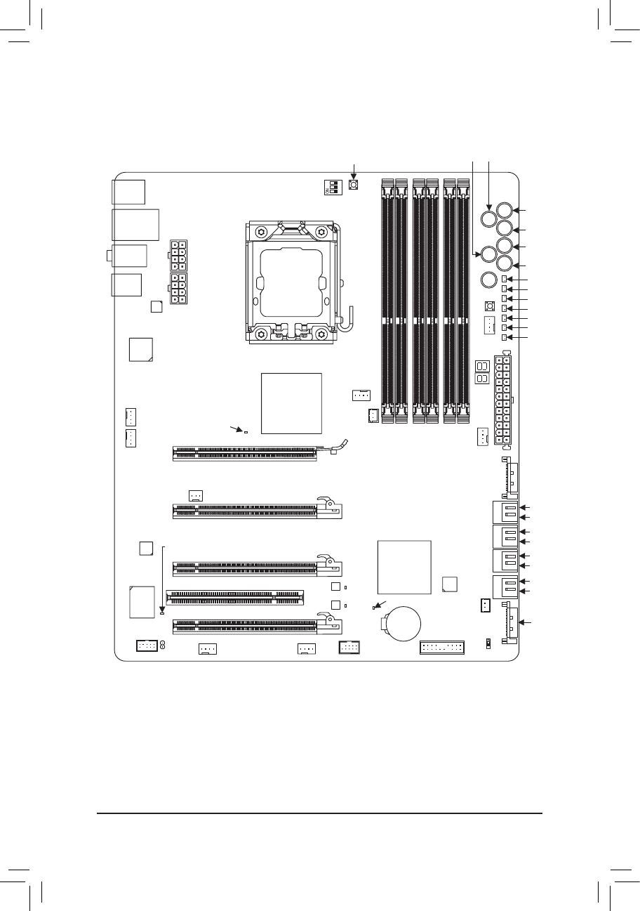
The six DDR3 memory sockets are divided into three channels:
Channel 0: DDR3_1, DDR3_2
Channel 1: DDR3_3, DDR3_4
Channel 2: DDR3_5, DDR3_6
1-4 Installing the Memory
DualChannelMemoryCongurationsTable
3ChannelMemoryCongurationsTable
(SS=Single-Sided, DS=Double-Sided, "- -"=No Memory)
Due to CPU limitation, read the following guidelines before installing the memory in Dual or 3 Channel mode.
Dual Channel--
1. Dual Channel mode cannot be enabled if only one DDR3 memory module is installed.
2. When enabling Dual Channel mode with two or four modules, it is recommended that memory of the same
capacity, brand, speed, and chips be used. When enabling Dual Channel mode with two memory modules,
be sure to install them in the DDR3_1 and DDR3_3 sockets.
3 Channel--
1. 3 Channel mode cannot be enabled if only one or two DDR3 memory modules are installed.
2. When enabling 3 Channel mode with three, four or six modules, it is recommended that memory of the
same capacity, brand, speed, and chips be used. When enabling 3 Channel mode with three memory
modules, be sure to install them in the DDR3_1, DDR3_3 and DDR3_5 sockets. When enabling 3 Channel
mode with four memory modules, be sure to install them in the DDR3_1, DDR3_2, DDR3_3 and DDR3_5
sockets.
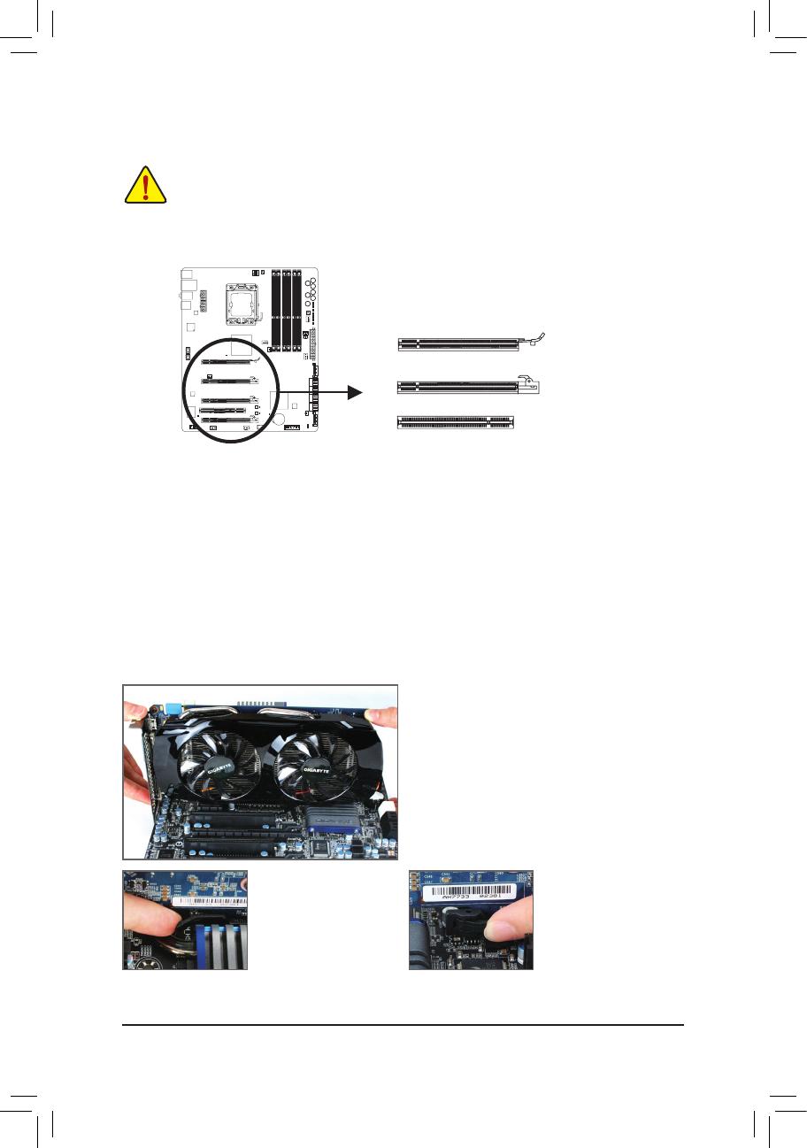
Read the following guidelines before you begin to install the memory:
Make sure that the motherboard supports the memory. It is recommended that memory of the
same capacity, brand, speed, and chips be used.
(Go to GIGABYTE's website for the latest supported memory speeds and momery modules.)
Always turn off the computer and unplug the power cord from the power outlet before installing
the memory to prevent hardware damage.
Memory modules have a foolproof design. A memory module can be installed in only one direc-
tion. If you are unable to insert the memory, switch the direction.
DDR3_2 DDR3_1 DDR3_4 DDR3_3 DDR3_6 DDR3_5
- - DS/SS - - DS/SS - - - -
DS/SS DS/SS DS/SS DS/SS - - - -
Two Modules
Four Modules
DDR3_2 DDR3_1 DDR3_4 DDR3_3 DDR3_6 DDR3_5
- - DS/SS - - DS/SS - - DS/SS
DS/SS DS/SS - - DS/SS - - DS/SS
DS/SS DS/SS DS/SS DS/SS DS/SS DS/SS
Three Modules
Four Modules
Six Modules
1
DIP
1 2 3
DDR3_2
DDR3_1
DDR3_4
DDR3_3
DDR3_6
DDR3_5
1
DIP
1 2 3
If only one DDR3 memory module is installed, be sure
to install it in the DDR3_1 or DDR3_3.
- 17 - Hardware Installation
1-4-2 Installing a Memory
Notch
DDR3 DIMM
ADDR3memorymodulehasanotch,soitcanonlytinonedirection.Followthestepsbelowtocorrectly
install your memory modules in the memory sockets.
Before installing a memory module, make sure to turn off the computer and unplug the power
cord from the power outlet to prevent damage to the memory module.
DDR3 and DDR2 DIMMs are not compatible to each other or DDR DIMMs. Be sure to install
DDR3 DIMMs on this motherboard.
1
DIP
1 2 3
1
DIP
1 2 3
Step 1:
Note the orientation of the memory module. Spread the retaining
clips at both ends of the memory socket. Place the memory module
onthesocket.Asindicatedinthepictureontheleft,placeyourn-
gers on the top edge of the memory, push down on the memory and
insert it vertically into the memory socket.
Step 2:
The clips at both ends of the socket will snap into place when the
memory module is securely inserted.
Hardware Installation - 18 -
1-5 Installing an Expansion Card
Follow the steps below to correctly install your expansion card in the expansion slot.
1. Locate an expansion slot that supports your card. Remove the metal slot cover from the chassis back panel.
2. Align the card with the slot, and press down on the card until it is fully seated in the slot.
3. Make sure the metal contacts on the card are completely inserted into the slot.
4. Secure the card’s metal bracket to the chassis back panel with a screw.
5. After installing all expansion cards, replace the chassis cover(s).
6. Turn on your computer. If necessary, go to BIOS Setup to make any required BIOS changes for your
expansion card(s).
7. Install the driver provided with the expansion card in your operating system.
Example: Installing and Removing a PCI Express Graphics Card:
Read the following guidelines before you begin to install an expansion card:
Make sure the motherboard supports the expansion card. Carefully read the manual that came
with your expansion card.
Always turn off the computer and unplug the power cord from the power outlet before installing
an expansion card to prevent hardware damage.
1
DIP
1 2 3
PCI Slot
PCI Express x16 Slot (PCIEX16_2/PCIEX8_1/PCIEX8_2)
PCI Express x16 Slot (PCIEX16_1)
Installing a Graphics Card:
Gently push down on the top edge of the card until
it is fully inserted into the PCI Express slot. Make
sure the card is securely seated in the slot and
does not rock.
Removing the Card from
the PCIEX16_1 Slot:
Gently push back on the
lever on the slot and then
lift the card straight out
from the slot.
Removing the Card
from the PCIEX16_2/
PCIEX8_1/PCIEX8_2 Slot:
Press the latch at the end
of the PCI Express slot
to release the card and
then pull the card straight
up from the slot.
- 19 - Hardware Installation
1-6 Setup of ATI CrossFireX
/NVIDIA SLI Conguration
A. System Requirements
- The 2-Way SLI and 2-Way CrossFireX technologies currently support Windows 7, Vista, and XP operating systems
- The 3-Way SLI and 3-Way/4-Way CrossFireX technologies currently support Windows 7 and Vista operating systems
- A CrossFireX/SLI-supported motherboard with two/three/four PCI Express x16 slots and correct driver
- CrossFireX/SLI-supported graphics cards of identical brand and chip and correct driver
( Current GPUs that support 3-Way/4-Way CrossFireX technology include the ATI Radeon HD 3800, HD 4800, and HD 5800
series and AMD Radeon HD 6950 and HD 6970 series. Current
GPUs that support 3-Way SLI technology include the NVIDIA
8800 GTX, 8800 Ultra, 9800 GTX, GTX 260, GTX 280, GTX 470, GTX 480, GTX 570, and GTX 580 series.)
- CrossFire
(Note 1)
/SLI bridge connector(s)
 - Apowersupplywithsufcientpowerisrecommended
(Note 2)
(Refer to the manual of your graphics cards for the power require-
ment)
B. Connecting the Graphics Cards
Step 1:
Observe the steps in "1-5 Installing an Expansion Card" and install CrossFireX/SLI graphics cards on the PCI Express x16
slots.(Tosetup a2-Way conguration, werecommend installing thegraphics cards onthe PCIEX16_1 andPCIEX16_2
slots.)
Step 2:
Insert the CrossFireX
(Note 1)
/SLI bridge connectors into the CrossFireX/SLI gold edge connectors on top of the graphics cards.
Step 3:
Plug the display cable into the graphics card on the PCIEX16_1 slot.
C. Conguring the Graphics Card Driver
C-1. To Enable CrossFireX Function
For 2-Way CrossFireX:
After installing the graphics card driver in the operating system, go to the Catalyst Con-
trol Center. Browse to the CrossFireX menu and ensure the Enable CrossFireX
check
box is selected.
For 3-Way CrossFireX:
After installing the graphics card driver in the operating system, go to the Catalyst Con-
trol Center. Browse to the CrossFireX menu, select the Enable CrossFireX
check
box, and select the 3 GPUs combination. Click OK to apply.
Hardware Installation - 20 -
(Note 1) The bridge connectors may be needed or not depending on your graphics cards.
(Note 2) When two or more graphics cards are installed, we recommend that you connect the SATA power
cable(s) from the power supply to the ATX4P1/ATX4P4 connector to ensure system stability.
For 4-way CrossFireX™, you must connect at least one of the ATX4P1 and ATX4P4 connectors.
For 2-Way/3-Way SLI:
After installing the graphics card driver in the operating system, go to the NVIDIA Control
Panel. Browse to the Set SLI and Physx Conguration screen and ensure Maximize
3D performance is enabled.
C-2. To Enable SLI Function
Procedure and driver screen for enabling CrossFireX/SLI technology may differ by graphics cards. Refer to the
manual that came with your graphics cards for more information about enabling CrossFireX/SLI technology.
For 4-Way CrossFireX:
After installing the graphics card driver in the operating system, go to the Catalyst Con-
trol Center. Browse to the CrossFireX menu, select the Enable CrossFireX
check box,
and select the 4 GPUs combination. Click OK to apply.
  • Page 1 1
  • Page 2 2
  • Page 3 3
  • Page 4 4
  • Page 5 5
  • Page 6 6
  • Page 7 7
  • Page 8 8
  • Page 9 9
  • Page 10 10
  • Page 11 11
  • Page 12 12
  • Page 13 13
  • Page 14 14
  • Page 15 15
  • Page 16 16
  • Page 17 17
  • Page 18 18
  • Page 19 19
  • Page 20 20
  • Page 21 21
  • Page 22 22
  • Page 23 23
  • Page 24 24
  • Page 25 25
  • Page 26 26
  • Page 27 27
  • Page 28 28
  • Page 29 29
  • Page 30 30
  • Page 31 31
  • Page 32 32
  • Page 33 33
  • Page 34 34
  • Page 35 35
  • Page 36 36
  • Page 37 37
  • Page 38 38
  • Page 39 39
  • Page 40 40
  • Page 41 41
  • Page 42 42
  • Page 43 43
  • Page 44 44
  • Page 45 45
  • Page 46 46
  • Page 47 47
  • Page 48 48
  • Page 49 49
  • Page 50 50
  • Page 51 51
  • Page 52 52
  • Page 53 53
  • Page 54 54
  • Page 55 55
  • Page 56 56
  • Page 57 57
  • Page 58 58
  • Page 59 59
  • Page 60 60
  • Page 61 61
  • Page 62 62
  • Page 63 63
  • Page 64 64
  • Page 65 65
  • Page 66 66
  • Page 67 67
  • Page 68 68
  • Page 69 69
  • Page 70 70
  • Page 71 71
  • Page 72 72
  • Page 73 73
  • Page 74 74
  • Page 75 75
  • Page 76 76
  • Page 77 77
  • Page 78 78
  • Page 79 79
  • Page 80 80
  • Page 81 81
  • Page 82 82
  • Page 83 83
  • Page 84 84
  • Page 85 85
  • Page 86 86
  • Page 87 87
  • Page 88 88
  • Page 89 89
  • Page 90 90
  • Page 91 91
  • Page 92 92
  • Page 93 93
  • Page 94 94
  • Page 95 95
  • Page 96 96
  • Page 97 97
  • Page 98 98
  • Page 99 99
  • Page 100 100
  • Page 101 101
  • Page 102 102
  • Page 103 103
  • Page 104 104
  • Page 105 105
  • Page 106 106
  • Page 107 107
  • Page 108 108
  • Page 109 109
  • Page 110 110
  • Page 111 111
  • Page 112 112
  • Page 113 113
  • Page 114 114
  • Page 115 115
  • Page 116 116
  • Page 117 117
  • Page 118 118
  • Page 119 119
  • Page 120 120

Gigabyte GA-X58A-OC Owner's manual

Category
Motherboards
Type
Owner's manual

Ask a question and I''ll find the answer in the document

Finding information in a document is now easier with AI