
filename[010COV.FM] model name1[SLV-N81] model name2[SLV-N71]
[3-065-551-11 (1)]
3-065-551-11 (1)
Video Cassette
Recorder
Operating Instructions
If you have any questions about this product, you may call: Sony
Customer Information Services Center 1-800-222-SONY (7669) or
write to: Sony Customer Information Services Center 6900-29
Daniels Parkway, PMB 330, Fort Myers, FL 33912
Declaration of Conformity
Trade Name: SONY
Model No.: SLV-N81/N71
Responsible Party: Sony Electronics Inc.
Address: 1 Sony Drive, Park Ridge, NJ.07656 USA
Telephone No.: 201-930-6972
This device complies with Part 15 of the FCC Rules. Operation is subject to
the following two conditions: (1) This device may not cause harmful
interference, and (2) this device must accept any interference received,
including interference that may cause undesired operation.
SLV-N81
SLV-N71
© 2001 Sony Corporation

2
WARNING
filename[010WAR.FM] model name1[SLV-N81] model name2[SLV-N71]
[3-065-551-11 (1)]
WARNING
To prevent fire or shock hazard, do not
expose the unit to rain or moisture.
This symbol is intended to alert the user
to the presence of uninsulated
“dangerous voltage”withinthe product’s
enclosure that may be of sufficient
magnitude to constitute a risk of electric
shock to persons.
This symbol is intended to alert the user
to the presence of important operating
and maintenance (servicing) instructions
in the literature accompanying the
appliance.
CAUTION
To prevent electric shock, do not use this polarized
AC plug with an extension cord, receptacle or other
outlet unless the blades can be fully inserted to
prevent blade exposure.
Precautions
Safety
• Operate the unit only on 120 V AC, 60 Hz.
• If anything falls into the cabinet, unplug the unit
and have it checked by qualified personnel before
operating it any further.
• This unit is not disconnected from the AC power
source (mains) as long as it is connected to the
wall outlet, even if the unit itself has been turned
off.
• Unplug the unit from the wall outlet if you do not
intend to use it for an extended period of time. To
disconnect the cord, pull it out by the plug, never
by the cord.
• One blade of the plug is wider than the other for
the purpose of safety and will fit into the power
outlet only one way. If you are unable to insert
the plug fully into the outlet, contact your Sony
dealer.
Installing
• Allow adequate air circulation to prevent internal
heat buildup.
• Do not place the unit on surfaces (rugs, blankets,
etc.) or near materials (curtains, draperies) that
may block the ventilation slots.
• Do not install the unit near heat sources such as
radiators or air ducts, or in a place subject to
direct sunlight, excessive dust, mechanical
vibration or shock.
• Do not install the unit in an inclined position. It
is designed to be operated in a horizontal position
only.
• Keep the unit and cassettes away from equipment
with strong magnets, such as microwave ovens or
large loudspeakers.
• Do not place heavy objects on the unit.
• If the unit is brought directly from a cold to a
warm location, moisture may condense inside the
VCR and cause damage to the video head and
tape. When you first install the unit, or when you
move it from a cold to a warm location, wait for
about three hours before operating the unit.
Information
For customers in the USA
CAUTION
You are cautioned that any changes or modifications
not expressly approved in this manual could void
your authority to operate this equipment.
NOTE:
This equipment has been tested and found to
comply with the limits for a Class B digital device,
pursuant to Part 15 of the FCC Rules.
These limits are designed to provide reasonable
protection against harmful interference in a
residential installation.
This equipment generates, uses, and can radiate
radio frequency energy and, if not installed and used
in accordance with the instructions, may cause
harmful interference to radio communications.
However, there is no guarantee that interference will
not occur in a particular installation. If this
equipment does cause harmful interference to radio
or television reception, which can be determined by
turning the equipment off and on, the user is
encouraged to try to correct the interference by one
or more of the following measures:
• Reorient or relocate the receiving antenna.
• Increase the separation between the equipment
and receiver.
• Connect the equipment into an outlet on a circuit
different from that to which the receiver is
connected.
• Consult the dealer or an experienced radio/TV
technician for help.
Owner’s record
The model and serial numbers are located at the rear
of the unit.
Record these numbers in the spaces provided below.
Refer to them whenever you call upon your Sony
dealer regarding this product.
Model No._________________________
Serial No._________________________

3
Important Safeguards
filename[010WAR.FM] model name1[SLV-N81] model name2[SLV-N71]
[3-065-551-11 (1)]
Important Safeguards
For your protection, please read these safety
instructions completely before operating the
appliance, and keep this manual for future reference.
Carefully observe all warnings, precautions and
instructions on the appliance, or the one described in
the operating instructions and adhere to them.
Use
Installation
Power sources
This set should be operated only
from the type of power source
indicated on the marking label. If
you are not sure of the type of
electrical power supplied to your
home, consult your dealer or local power company.
For those sets designed to operate from battery
power, or other sources, refer to the operating
instructions.
Grounding or Polarization
This set is equipped with a polarized ac power cord
plug (a plug having one blade wider than the other),
or with a three-wire grounding type plug (a plug
having a third pin for grounding). Follow the
instructions below:
For the set with a polarized ac power cord
plug:
This plug will fit into the power
outlet only one way. This is a
safety feature. If you are unable
to insert the plug fully into the outlet, try reversing
the plug. If the plug should still fail to fit, contact
your electrician to have a suitable outlet installed.
Do not defeat the safety purpose of the polarized
plug by forcing it in.
For the set with a three-wire grounding
type ac plug:
This plug will only fit into a
grounding-type power outlet.
This is a safety feature. If you are
unable to insert the plug into the outlet, contact your
electrician to have a suitable outlet installed. Do not
defeat the safety purpose of the grounding plug.
Overloading
Do not overload wall outlets,
extension cords or convenience
receptacles beyond their capacity,
since this can result in fire or
electric shock.
Object and Liquid Entry
Never push objects of any kind into
the set through openings as they
may touch dangerous voltage
points or short out parts that could
resultinafireorelectricshock.
Never spill liquid of any kind on the set.
Attachments
Do not use attachments not
recommended by the manufacturer, as
they may cause hazards.
Cleaning
Unplug the set from the wall
outlet before cleaningorpolishing
it. Do not use liquid cleaners or
aerosol cleaners. Use a cloth
lightly dampened with water for
cleaning the exterior of the set.
Water and Moisture
Do not use power-line operated sets
near water - for example, near a
bathtub, washbowl, kitchen sink, or
laundry tub, in a wet basement, or
near a swimming pool, etc.
Power-Cord Protection
Route the power cord so that it is
notlikelytobewalkedonor
pinched by items placed upon or
against them, paying particular attention to the
plugs, receptacles, and the point where the cord exits
from the appliance.
Accessories
Do not place the set on an
unstable cart, stand, tripod,
bracket, or table. The set may
fall, causing serious injury to a
child or an adult, and serious damage to the set. Use
only a cart stand tripod, bracket, or table
recommended by the manufacturer.
An appliance and cart
combination should be moved
with care. Quick stops, excessive
force, and uneven surfaces may
cause the appliance and cart
combination to overturn.
Ventilation
The slots and openings in the cabinet are provided for
necessary ventilation. To ensure reliable operation of
the set, and to protect it from overheating, these slots
and openings must never be blocked or covered.
• Never cover the slots and
openings with a cloth or other
materials.
• Never block the slots and
openings by placing the set on
a bed, sofa, rug or other similar
surface.
S3125A

4
Important Safeguards
filename[010WAR.FM] model name1[SLV-N81] model name2[SLV-N71]
[3-065-551-11 (1)]
Antennas
Service
• Never place the set in a
confined space, such as a
bookcase, or built-in cabinet,
unless proper ventilation is
provided.
• Do not place the set near or
over a radiator or heat register,
or where it is exposed to direct
sunlight.
Outdoor antenna grounding
If an outdoor antenna or cable system is installed,
follow the precautions below.
An outdoor antenna system should not be located in
the vicinity of overhead power lines or other electric
light or power circuits, or where it can come in
contact with such power lines or circuits.
WHEN INSTALLING AN OUTDOOR ANTENNA
SYSTEM, EXTREME CARE SHOULD BE
TAKEN TO KEEP FROM CONTACTING SUCH
POWER LINES OR CIRCUITS AS CONTACT
WITH THEM IS ALMOST INVARIABLY FATAL.
Be sure theantenna systemis grounded soas toprovide
some protection against voltage surges and built-up
static charges. Section 810 of the National Electrical
Code provides information with respect to proper
grounding of the mast and supporting structure,
grounding of the lead-in wire to an antenna discharge
unit, size of grounding conductors, location of antenna-
discharge unit, connection to grounding electrodes, and
requirements for the grounding electrode.
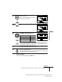
Antenna Grounding According to the
National Electrical Code
Lightning
For added protection for this set during a lightning
storm, or when it is left unattended and unused for
long periods of time, unplug it from the wall outlet
and disconnect the antenna or cable system. This
will prevent damage to the set due to lightning and
power-line surges.
Antenna Lead in Wire
Ground Clamp
Antenna Discharge unit
(NEC Section 810-20)
Grounding Conductors
(NEC Section 810-21)
Ground Clamps
Power Service Grounding
Electrode System
(NEC Art 250 Part H)
Electric Service
Equipment
NEC-NATIONAL ELECTRICAL CODE
Damage Requiring Service
Unplug the set from the wall outlet and refer
servicing to qualified service personnel under the
following conditions:
• When the power cord or plug is
damaged or frayed.
• If liquid has been spilled or
objects have fallen into the set.
• If the set has been exposed to
rain or water.
• If the set has been subject
to excessive shock by
being dropped, or the
cabinet has been damaged.
• If the set does not operate
normally when following the
operating instructions. Adjust
only those controls that are
specified in the operating
instructions. Improper adjustment of other
controls may result in damage and will often
require extensive work by a qualified technician
to restore the set to normal operation.
• When the set exhibits a distinct change in
performance - this indicates a need for service.
Servicing
Do not attempt to service the set
yourself as opening or removing
covers may expose you to
dangerous voltage or other
hazards.
Refer all servicing to qualified service personnel.
Replacement parts
When replacement parts are required, be sure the
service technician has used replacement parts
specified by the manufacturer that have the same
characteristics as the original parts.
Unauthorized substitutions may result in fire,
electric shock, or other hazards.
Safety Check
Upon completion of any service
or repairs to the set, ask the
service technician to perform
routine safety checks (as specified
by the manufacturer) to determine
that the set is in safe operating
condition.

5
Table of contents
Getting Started
filename[010COVtoc.FM] model name1[SLV-N80] model name2[SLV-N70]
[3-065-551-11 (1)]
Table of contents
Getting Started
6 Step 1 : Unpacking
7 Step 2 : Setting up the remote commander
9 Step 3 : Hookups
27 Selecting a language
28 Setting the clock
35 Setting up the cable box control (SLV-N81 only)
41 Presetting channels
48 Setting up the VCR Plus+® GOLD system (SLV-N81 only)
55 Setting up the VCR Plus+® system (SLV-N71 only)
Basic Operations
59 Playing a tape
62 Recording TV programs
65 Recording TV programs using the
Dial Timer
70 Recording TV programs using the
VCR Plus+ or VCR Plus+ GOLD
system
73 Setting the timer manually
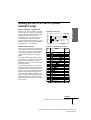
76 Locking the VCR (Child Lock)
Additional Operations
77 Playing/searching at various speeds
79 Setting the recording duration time
80 Checking/changing/canceling timer
settings
82 Recording stereo and bilingual
programs
84 Searching using the index function
85 Searching for a selected point on the
tape
87 Locating a channel by Station ID
(SLV-N81 only)
88 Creating a favorite channel list with
Station ID (SLV-N81 only)
90 Adjusting the picture
92 Changing menu options
94 Editing with another VCR
Additional Information
96 General setup information
98 Troubleshooting
100 Specifications
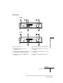
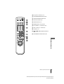
101 Index to parts and controls
106 Index
Back Cover
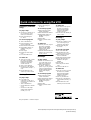
Quick reference to using the VCR
VCR Plus+, C
3
, ALLSET and PlusCode are trademarks of Gemstar Development Corporation.
The VCR Plus+ system is manufactured under license from Gemstar Development Corporation.
Caution
Television programs, films, video tapes and other materials may be copyrighted.
Unauthorized recording of such material may becontrary to the provisions of the copyright laws. Also, use
of this recorder with cable television transmission may require authorization from the cable television
transmission and/or program owner.

6
Unpacking
filename[010get.fm] model name1[SLV-N81] model name2[SLV-N71]
[3-065-551-11 (1)]
Getting Started
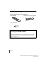
Step 1 : Unpacking
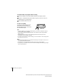
Check that you have received the following items with the VCR:
• Remote commander • 75-ohm coaxial cable with F-type connectors
• Size AA (R6) batteries
Check your model name
The instructions in this manual are for the 2 models: SLV-N81 and N71. Check your
model name by looking at the rear panel of your VCR. SLV-N81 is the model used for
illustration purposes. Any difference in operation is clearly indicated in the text, for
example, “SLV-N81 only.”

Getting Started
7
Setting up the remote commander
filename[010get.fm] model name1[SLV-N81] model name2[SLV-N71]
[3-065-551-11 (1)]
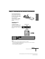
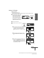
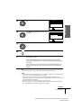
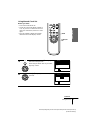
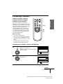
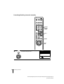
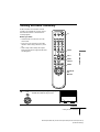
Step2:Settinguptheremotecommander
Notes
• With normal use, the batteries should last about three to six months.
• If you do not use the remote commander for an extended period of time, remove the batteries
to avoid possible damage from battery leakage.
• Do not use a new battery with an old one.
• Do not use different types of batteries.
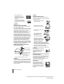
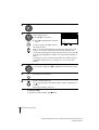
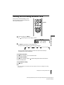
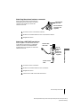
Inserting the batteries
Insert two size AA (R6) batteries
by matching the + and – on the
batteries to the diagram inside the
battery compartment.
Insert the negative (–) end first,
then push in and down until the
positive (+) end clicks into
position.
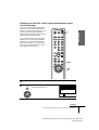
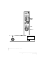
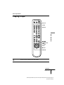
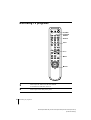
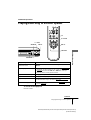
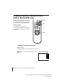
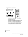
Using the remote
commander
You can use this remote
commander to operate this VCR
and a Sony TV. Buttons on the
remote commander marked with a
dot (•) can be used to operate your
Sony TV.
To operate
Set
•TV /VIDEOto
the VCR VIDEO
and point at the remote sensor at the VCR
a Sony TV •TV
and point at the remote sensor at the TV
123
•TV /VIDEO
Remote sensor
continued

8
Setting up the remote commander
filename[010get.fm] model name1[SLV-N81] model name2[SLV-N71]
[3-065-551-11 (1)]
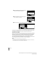
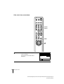
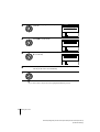
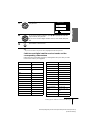
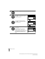
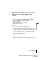
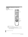
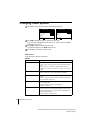
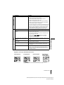
Controlling other TVs with the remote commander
The remote commander is preprogrammed to control non-Sony TVs. If your TV is
listed in the following table, set the appropriate manufacturer’s code number.
Now you can use the ?/1, VOL +/–, CH +/–, and TV/VIDEO buttons to control your
TV. You can also use the buttons marked with a dot (•) to control a Sony TV. To
control the VCR, reset •TV
/VIDEOto VIDEO.
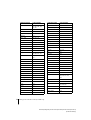
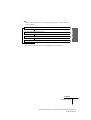
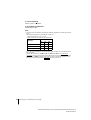
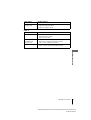
Code numbers of controllable TVs
If more than one code number is listed, try entering them one at a time until you find
the one that works with your TV.
Notes
• If you enter a new code number, the code number previously entered will be erased.
• If the TV uses a different remote control system from the one programmed to work with the
VCR, you cannot control your TV with the remote commander.
• When you replace the batteries of the remote commander, the code number may change. Set
the appropriate code number every time you replace the batteries.
• When you press the AUDIO MONITOR button, your TV’s menu may appear on the TV
screen. To exit the TV menu, press the MENU button on the TV remote commander or wait
until the menu disappears automatically.
1
Set •TV /VIDEOatthetopoftheremotecommanderto•TV.
2
Hold down ?/1, and enter your TV’s code number using the number buttons.
Then release ?/1.
TV brand
Code
number
Sony 01
Akai 04
AOC 04
Centurion 12
Coronado 03
Curtis-Mathes 12
Daytron 12
Emerson 03, 04, 14
Fisher 11
General Electric 06, 10
Gold Star 03, 04, 17
Hitachi 02, 03
J.C.Penney 04, 12
JVC 09
KMC 03
Magnavox 03, 08, 12
Marantz 04, 13
MGA/Mitsubishi
04, 12, 13, 17
NEC 04, 12
Panasonic 06, 19
Philco 03, 04
Philips 08
Pioneer 16
Portland 03
Quasar 06, 18
Radio Shack 05, 14
TV brand
Code
number
RCA 04, 10
Sampo 12
Sanyo 11
Scott 12
Sears 07, 10, 11
Sharp 03, 05, 18
Sylvania 08, 12
Teknika 03, 08, 14
Toshiba 07
Wards 03, 04, 12
Yor x 12
Zenith 15
TV brand
Code
number

Getting Started
9
Hookups
filename[010get.fm] model name1[SLV-N81] model name2[SLV-N71]
[3-065-551-11 (1)]
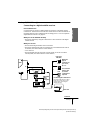
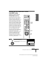
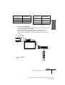
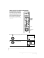
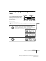
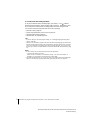
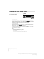
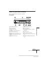
Step 3 : Hookups
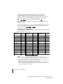
Selecting the best hookup option
There are many ways in which your VCR can be hooked up. To hook up your VCR
so that it works best for you, first scan through the table below. Then use the
accompanying diagrams and procedures on the following pages to set up your VCR.
If your TV has audio/video inputs, refer to pages 10 and 11 for audio/video (A/V)
hookup. Then follow one of the hookups below. If your TV doesn’t have A/V inputs,
go directly to one of the hookups below.
For hookup 1 or 2, use the Sony RM-CM101 Cable Mouse (cable box controller) (not
supplied). For details on obtaining a Cable Mouse controller, contact the Sony
Customer Information Services Center.
For SLV-N81 only
For both SLV-N81 and N71
After you’ve completed the connections, follow the instructions for setup. During
setup, if you need more details on the procedure described, page numbers are
provided where you can find complete, step-by-step instructions.
After you’ve completed the setup, you’re ready to use your VCR. Procedures differ
depending on the hookup you used. For an overview, refer to “Quick reference to
using the VCR” on the back cover.
Before you get started
• Turn off the power to all equipment.
• Do not connect the AC power cords until all of the connections are completed.
• Be sure to make connections firmly. Loose connections may cause picture
distortion.
• If your TV doesn’t match any of the examples provided, see your nearest Sony
dealer or qualified technician.
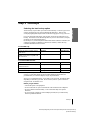
If you have Use Refer to
A cable box that is compatible with the
Cable Mouse
Hookup 1 Pages 12 to 14
A digital broadcast service’s digital
satellite receiver that is compatible with
the Cable Mouse
Hookup 2 Pages 15 to 17
If you have Use Refer to
No cable box or cable box with only a few
scrambled channels
Hookup 3 Pages 18 to 20
Antenna only, no cable TV Hookup 4 Pages 21 to 23
Cable box with many scrambled channels Hookup 5 Pages 24 to 26

10
Hookups
filename[010get.fm] model name1[SLV-N81] model name2[SLV-N71]
[3-065-551-11 (1)]
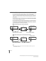
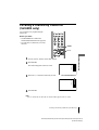
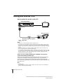
Audio/video (A/V) hookup
If your TV has audio/video (A/V) input jacks, you will get a better picture and sound
if you hook up your VCR using these connections. For a true “home theater”
experience, you should connect the audio outputs of your VCR or TV to your stereo
system. If your TV doesn’t have A/V inputs, see the following pages for antenna or
cable hookups.
If your TV has the Control S function, hook up your VCR (SLV-N81 only) using the
connection shown on page 11. This will allow you to operate your VCR by pointing
your VCR’s remote commander at your TV.
If you’re not planning to use your VCR to record programs, you’re finished setting up
the VCR after you’ve made the connections shown on pages 10 and 11. If you want
to record regular or cable TV programs, complete these connections first, and then go
to the following pages for antenna or cable hookups.
A Use this hookup if your TV has stereo jacks
B Use this hookup if your TV doesn’t have stereo jacks
Note
• If you don’t have a stereo receiver, connect the white LINE OUT/AUDIO L jack to the
AUDIOINjackonyourTV.
LINE-1
IN
LINE
OUT
AUDIO VIDEO
IN
VIDEO
AUDIO
AUDIO OUT
AUX IN
Audio/video cable (not supplied)
TV
Audio cable (not supplied)
Stereo receiverVCR
VIDEO
AUDIO
IN
AUX IN
LINE-1
IN
LINE
OUT
AUDIO VIDEO
Video cable (not supplied)
TV
Audio cable (not supplied)
Stereo receiverVCR

Getting Started
11
Hookups
filename[010get.fm] model name1[SLV-N81] model name2[SLV-N71]
[3-065-551-11 (1)]
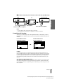
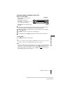
C Use this hookup if your TV has the Control S function (SLV-N81 only)
Notes
• To play a tape in stereo, you must use the A/V connection.
• Use the RK-G69 Control S cable (not supplied) for Control S connections.
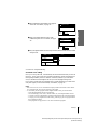
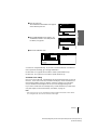
Completing A/V hookup:
After you’ve connected your TV and completed antenna or cable hookup, return to
this procedure to complete VCR set up. This will prevent unwanted noise in the RF
channel.
Caution
Connections between the VCR’s VHF/UHF connector and the antenna terminals of the TV
receiver should be made only as shown in the following instructions. Failure to do so may result
in operation that violates the regulations of the Federal Communications Commission regarding
the use and operation of RF devices. Never connect the output of the VCR to an antenna or
make simultaneous (parallel) antenna and VCR connections at the antenna terminals of your
receiver.
Note to CATV system installer (in USA)
This reminder is provided to call the CATV system installer’s attention to Article 820- 40 of the
NEC that provides guidelines for proper grounding and, in particular, specifies that the cable
ground shall be connected to the grounding system of the building, as close to the point of cable
entry as practical.
LINE-1
IN
LINE
OUT
IN
CONTROL S
AUDIO VIDEO
IN
VIDEO
AUDIO
AUDIO OUT
AUX IN
CONTROL S OUT
Audio/video cable
(not supplied)
TV
Audio cable (not supplied)
Stereo receiverVCR
Control S cable (not supplied)
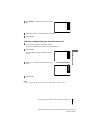
SET :
SELECT :
OK
MENUQUIT :
TIMER SET/CHECK
SETTINGS
ADVANCED OPTIONS
SET :
SELECT :
OK
MENUQUIT :
ADVANCED OPTIONS
PAGE1
AUTO STEREO
AUTO ANT SELECT
TUNER AUDIO
TAPE SELECT
AUTO TAPE SPEED
OFF
ON
AUTO
FAVORITE CH
ON
ON
NEXT
RETURN
Press MENU and select
ADVANCED OPTIONS.
Set AUTO ANT SELECT
to OFF and press OK.
For details, see page 92.
,

12
Hookups
filename[010get.fm] model name1[SLV-N81] model name2[SLV-N71]
[3-065-551-11 (1)]
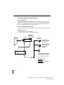
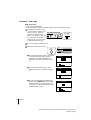
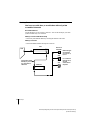
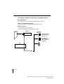
Hookup 1 (SLV-N81 only)
Using the cable box control feature
Recommended use
You should use this hookup if you have a cable box, especially if your cable system
scrambles all or most channels. This hookup allows the VCR’s cable box control
feature to control the channels on the cable box, simplifying the recording process. A
list of compatible cable boxes is on pages 37 and 38.
What you can do with this hookup
• Record any channel by using the Cable Mouse to select channels on the cable box
What you can’tdo
• Record with the cable box turned off
• Record one channel while watching another channel
CONTROL S
( )
CABLE BOX
CONTROL
PLUG IN
POWER
OUT
IN
OUT
VHF/UHF
IN
OUT
RearofTV
VHF/UHF
RM-CM101
Cable Mouse
(not supplied)
VHF
UHF
Positioning the Cable Mouse
Place the Cable Mouse so that it
hangs out over the front of the
remote sensor on the cable box.
VCR
Wall
Match the type of
connector on your
TV:A,B,orC.
For connector types
BandC,noUHF
connection is
required.
B
C
Side view
or
or
Cable box
A
VHF
UHF

Getting Started
13
Hookups
filename[010get.fm] model name1[SLV-N81] model name2[SLV-N71]
[3-065-551-11 (1)]
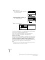
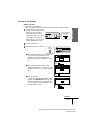
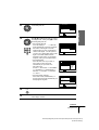
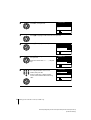
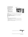
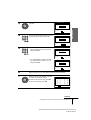
Hookup 1 : VCR setup
Before you start…
• Turn on the VCR and the TV.
• Press TV/VIDEO to display the VIDEO indicator in the VCR’s display window.
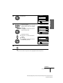
1
SettheRFUNITswitchtoCH3
or CH4, whichever channel is not
used in your area. If both are
used, set the switch to either
channel. For details, see page 96.
If you made A/V connections
(from page 10), you do not need
to adjust the RF UNIT switch.
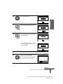
2
Turn on your cable box.
3
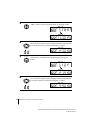
Press EASY SET UP on the VCR.
1 The LANGUAGE menu appears. Change the
on-screen display language to Spanish
(ESPAÑOL) or French (FRANÇAIS) if
desired, and press OK. For details, see page
27.
2 The CLOCK SET menu appears. Select
AUTO and press OK. For details, see page
29.
3 The SMART CHANNEL MAPPING menu
appears. Press M/m/</, to enter the ZIP/
POSTAL CODE in your area and press OK.
(You can also use the number buttons to enter
the ZIP/POSTAL CODE.)
CH3
RF UNIT
CH4
EASY
SET UP
SET UP
LANGUAGE
NEXT :
SELECT :
OK
EASY SET UPCANCEL :
ENGLISH
ESPAÑOL
FRANÇAIS
NEXT :
SELECT :
OK
AUTO
MANUAL
SET UP
CLOCK SET
EASY SET UPCANCEL :
NEXT :
SET :
OK
0–9
SELECT :
ZIP / POSTAL CODE
––––3
SET UP
SMART CHANNEL MAPPING
EASY SET UPCANCEL :
continued

14
Hookups
filename[010get.fm] model name1[SLV-N81] model name2[SLV-N71]
[3-065-551-11 (1)]
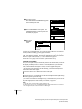
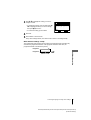
You have now completed hookup. If you want to use the VCR Plus+ GOLD system
for recording, go to page 48 for VCR Plus+ GOLD system channel set up.
Automatic clock setting
Once you’ve set up the VCR, it automatically sets the clock the first time you turn off
the VCR. “ACS” (Auto Clock Set) will flash in the display window and search for a
time signal provided by some TV channels. After that, whenever you turn off the
VCR, it checks the time and adjusts the clock, even for Daylight Saving Time.
If you want to use the timer to record right away, or if the channels in your area do not
carry time signals, set the clock manually. For details, see page 33.
Notes
• To use the Auto Clock Set feature, leave the cable box on.
• If the clock is not set, “ACS” will flash in the display window whenever the VCR is turned
off. During this time, the VCR will search for a time signal.
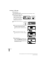
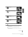
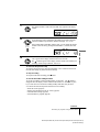
4 The CABLE BOX CONTROL menu appears.
Select ON. For details, see page 36.
5 Enter your cable box code number and press
OK. For details, see page 36.
6 Select your cable box output channel and press OK.
NEXT :
SELECT :
OK
SET UP
CABLE BOX CONTROL
EASY SET UPCANCEL :
CABLE MOUSE
BOX CODE NO.
BOX OUTPUT CH
OFF
ON
NEXT :
USE :
OK
0–9
SET UP
CABLE BOX CONTROL
EASY SET UPCANCEL :
CABLE MOUSE
BOX CODE NO.
BOX OUTPUT CH
ON
CH3
–––
SET UP
SET UP IS DONE
NEXT :
SELECT :
OK
SET UP
CABLE BOX CONTROL
EASY SET UPCANCEL :
CABLE MOUSE
BOX CODE NO.
BOX OUTPUT CH
ON
CH2
LINE
CH4
CH3

Getting Started
15
Hookups
filename[010get.fm] model name1[SLV-N81] model name2[SLV-N71]
[3-065-551-11 (1)]
Hookup 2 (SLV-N81 only)
Connecting to a digital satellite receiver
Recommended use
Use this hookup if you have a digital satellite receiver that is compatible with the
Cable Mouse. It allows the VCR’s cable box control feature to control the channel on
the digital satellite receiver, simplifying the recording process. A list of compatible
digital satellite receivers is on page 39.
What you can do with this hookup
• Record any channels by using the Cable Mouse to select channels on the digital
satellite receiver
What you can’tdo
• Record with the digital satellite receiver turned off
• Record any channels from cable or an antenna (To record channels from cable or
an antenna, turn off the cable box control feature.)
• Useacablebox
• Record programs with the VCR Plus+ GOLD system (To use the VCR Plus+
GOLD system, turn off the cable box control feature.)
LINE-1
IN
LINE
OUT
AUDIO VIDEO
IN
OUT
VHF/UHF
AUDIO VIDEO
LINE
OUT
OUT
VHF/UHF
IN
CONTROL S
( )
CABLE BOX
CONTROL
PLUG IN
POWER
OUT
Rear of TV
VHF/UHF
VHF
UHF
Positioning the Cable Mous
e
Place the Cable Mouse so that it
hangs out over the front of the
remote sensor on the digital
satellite receiver.
VCR
Wall
Match the
type of
connectoron
your TV: A,
B, or C.
Forconnector
types B and
C, no UHF
connection is
required.
B
C
Side view
or
or
A
VHF
UHF
Digital satellite
receiver
RM-CM101
Cable
Mouse
(not supplied)
or
continued

16
Hookups
filename[010get.fm] model name1[SLV-N81] model name2[SLV-N71]
[3-065-551-11 (1)]
Hookup 2 : VCR setup
Before you start…
• Turn on the VCR and the TV.
• Press TV/VIDEO to display the VIDEO indicator in the VCR’s display window.
1
Set the RF UNIT switch to CH3
or CH4, whichever channel is not
used in your area. If both are
used, set the switch to either
channel. For details, see page 96.
If you made A/V connections
(from page 10), you do not need
to adjust the RF UNIT switch.
2
Turn on your digital satellite receiver.
3
Press EASY SET UP on the VCR.
1 The LANGUAGE menu appears. Change the
on-screen display language to Spanish
(ESPAÑOL) or French (FRANÇAIS) if
desired, and press OK. For details, see page
27.
2 The CLOCK SET menu appears. Select
AUTO and press OK. For details, see page
29.
3 The SMART CHANNEL MAPPING menu
appears. Press M/m/</, to enter the ZIP/
POSTAL CODE in your area and press OK.
(You can also use the number buttons to enter
the ZIP/POSTAL CODE.)
CH3
RF UNIT
CH4
EASY
SET UP
SET UP
LANGUAGE
NEXT :
SELECT :
OK
EASY SET UPCANCEL :
ENGLISH
ESPAÑOL
FRANÇAIS
NEXT :
SELECT :
OK
AUTO
MANUAL
SET UP
CLOCK SET
EASY SET UPCANCEL :
NEXT :
SET :
OK
0–9
SELECT :
ZIP / POSTAL CODE
––––3
SET UP
SMART CHANNEL MAPPING
EASY SET UPCANCEL :

Getting Started
17
Hookups
filename[010get.fm] model name1[SLV-N81] model name2[SLV-N71]
[3-065-551-11 (1)]
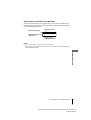
You have now completed hookup.
Automatic clock setting
Once you’ve set up the VCR, it automatically sets the clock the first time you turn off
the VCR. “ACS” (Auto Clock Set) will flash in the display window and search for a
time signal provided by some TV channels. After that, whenever you turn off the
VCR, it checks the time and adjusts the clock, even for Daylight Saving Time.
If you want to use the timer to record right away, or if the channels inyour area do not
carry time signals, set the clock manually. For details, see page 33.
Notes
• If the clock is not set, “ACS” will flash in the display window whenever the VCR is turned
off. During this time, the VCR will search for a time signal.
• To successfully record a program from the digital satellite receiver, proceed as follows:
– Leave the digital satellite receiver on all the time.
– Turn off the display (menu screen, channel number, etc.) of the digital satellite receiver.
– To record or receive locked channels, unlock the channel before the VCR starts recording.
– To set pay-per-view programs in the timer setting, order the pay-per-view program before
the VCR starts recording.
– Some programs are copy protected. You cannot record these programs.
4 The CABLE BOX CONTROL menu appears.
Select ON. For details, see page 36.
5 Enter your digital satellite receiver code
number and press OK. For details, see page
36.
6 Set your digital satellite receiver output channel (BOX OUTPUTCH) to LINE
and press OK.
NEXT :
SELECT :
OK
SET UP
CABLE BOX CONTROL
EASY SET UPCANCEL :
CABLE MOUSE
BOX CODE NO.
BOX OUTPUT CH
OFF
ON
NEXT :
USE :
OK
0–9
SET UP
CABLE BOX CONTROL
EASY SET UPCANCEL :
CABLE MOUSE
BOX CODE NO.
BOX OUTPUT CH
ON
CH3
–––
SET UP
SET UP IS DONE
NEXT :
SELECT :
OK
SET UP
CABLE BOX CONTROL
EASY SET UPCANCEL :
CABLE MOUSE
BOX CODE NO.
BOX OUTPUT CH
ON
CH2
LINE
CH4
CH3

18
Hookups
filename[010get.fm] model name1[SLV-N81] model name2[SLV-N71]
[3-065-551-11 (1)]
Hookup 3
You have no cable box, or a cable box with only a few
scrambled channels
Recommended use
Use this hookup if you do not have a cable box. Also use this hookup if your cable
system scrambles only a few channels.
What you can do with this hookup
• Record any unscrambled channel by selecting the channel on the VCR
What you can’tdo
• Record scrambled channels that require a cable box
IN
OUT
VHF/UHF
IN
OUT
RearofTV
VHF/UHF
VHF
UHF
VCR
Match the type
of connector
on your TV: A,
B, or C.
For connector
types B and C,
no UHF
connection is
required.
B
C
or
or
Cable box
A
VHF
UHF
Wall
Connect this cable
directly to your TV if
you don’thavea
cable box.

Getting Started
19
Hookups
filename[010get.fm] model name1[SLV-N81] model name2[SLV-N71]
[3-065-551-11 (1)]
Hookup 3 : VCR setup
Before you start…
• Turn on the VCR and the TV.
• Press TV/VIDEO to display the VIDEO indicator in the VCR’s display window.
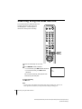
1
SettheRFUNITswitchtoCH3
or CH4, whichever channel is not
used in your area. If both are
used, set the switch to either
channel. For details, see page 96.
If you made A/V connections
(from page 10), you do not need
to adjust the RF UNIT switch.
2
Press EASY SET UP on the VCR.
1 The LANGUAGE menu appears. Change the
on-screen display language to Spanish
(ESPAÑOL) or French (FRANÇAIS) if
desired, and press OK. For details, see page
27.
2 The CLOCK SET menu appears. Select
AUTO and press OK. For details, see page
29.
3 (For SLV-N81 only)
The SMART CHANNEL MAPPING menu
appears. Press M/m/</, to enter the ZIP/
POSTAL CODE in your area and press OK.
(You can also use the number buttons to enter
the ZIP/POSTAL CODE.)
CH3
RF UNIT
CH4
EASY
SET UP
SET UP
LANGUAGE
NEXT :
SELECT :
OK
EASY SET UPCANCEL :
ENGLISH
ESPAÑOL
FRANÇAIS
NEXT :
SELECT :
OK
AUTO
MANUAL
SET UP
CLOCK SET
EASY SET UPCANCEL :
NEXT :
SET :
OK
0–9
SELECT :
ZIP / POSTAL CODE
––––3
SET UP
SMART CHANNEL MAPPING
EASY SET UPCANCEL :
continued

20
Hookups
filename[010get.fm] model name1[SLV-N81] model name2[SLV-N71]
[3-065-551-11 (1)]
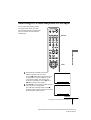
You have now completed hookup. If you want to use the VCR Plus+ or VCR Plus+
GOLD system for recording, go to the page listed below.
For SLV-N81: Go to page 48 for VCR Plus+ GOLD system channel set up.
ForSLV-N71:Gotopage55forVCRPlus+systemchannelsetup.
Automatic clock setting
Once you’ve set up the VCR, it automatically sets the clock the first time you turn off
the VCR. “ACS” (Auto Clock Set) will flash in the display window and search for a
time signal provided by some TV channels. After that, whenever you turn off the
VCR, it checks the time and adjusts the clock, even for Daylight Saving Time.
If you want to use the timer to record right away, or if the channels in your area do not
carry time signals, set the clock manually. For details, see page 33.
Note
• If the clock is not set, “ACS” will flash in the display window whenever the VCR is turned
off. During this time, the VCR will search for a time signal.
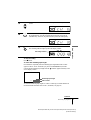
4 (For SLV-N81 only)
The CABLE BOX CONTROL menu appears.
Select OFF and press OK.
5 The TUNER PRESET menu appears. Set
ANTENNA/CABLE to CABLE and press
OK. For details, see page 42.
6 The AUTO PRESET starts.
NEXT :
SELECT :
OK
SET UP
CABLE BOX CONTROL
EASY SET UPCANCEL :
CABLE MOUSE
BOX CODE NO.
BOX OUTPUT CH
OFF
ON
NEXT :
SELECT :
OK
SET UP
TUNER PRESET
EASY SET UPCANCEL :
ANTENNA / CABLE
CABLE
ANT
SET UP
SET UP IS DONE
PLEASE WAIT
SET UP
TUNER PRESET CH 2 4
AUTO PRESET
PROCESSING
Page is loading ...
Page is loading ...
Page is loading ...
Page is loading ...
Page is loading ...
Page is loading ...
Page is loading ...
Page is loading ...
Page is loading ...
Page is loading ...
Page is loading ...
Page is loading ...
Page is loading ...
Page is loading ...
Page is loading ...
Page is loading ...
Page is loading ...
Page is loading ...
Page is loading ...
Page is loading ...
Page is loading ...
Page is loading ...
Page is loading ...
Page is loading ...
Page is loading ...
Page is loading ...
Page is loading ...
Page is loading ...
Page is loading ...
Page is loading ...
Page is loading ...
Page is loading ...
Page is loading ...
Page is loading ...
Page is loading ...
Page is loading ...
Page is loading ...
Page is loading ...
Page is loading ...
Page is loading ...
Page is loading ...
Page is loading ...
Page is loading ...
Page is loading ...
Page is loading ...
Page is loading ...
Page is loading ...
Page is loading ...
Page is loading ...
Page is loading ...
Page is loading ...
Page is loading ...
Page is loading ...
Page is loading ...
Page is loading ...
Page is loading ...
Page is loading ...
Page is loading ...
Page is loading ...
Page is loading ...
Page is loading ...
Page is loading ...
Page is loading ...
Page is loading ...
Page is loading ...
Page is loading ...
Page is loading ...
Page is loading ...
Page is loading ...
Page is loading ...
Page is loading ...
Page is loading ...
Page is loading ...
Page is loading ...
Page is loading ...
Page is loading ...
Page is loading ...
Page is loading ...
Page is loading ...
Page is loading ...
Page is loading ...
Page is loading ...
Page is loading ...
Page is loading ...
Page is loading ...
Page is loading ...
Page is loading ...
Page is loading ...
-
 1
1
-
 2
2
-
 3
3
-
 4
4
-
 5
5
-
 6
6
-
 7
7
-
 8
8
-
 9
9
-
 10
10
-
 11
11
-
 12
12
-
 13
13
-
 14
14
-
 15
15
-
 16
16
-
 17
17
-
 18
18
-
 19
19
-
 20
20
-
 21
21
-
 22
22
-
 23
23
-
 24
24
-
 25
25
-
 26
26
-
 27
27
-
 28
28
-
 29
29
-
 30
30
-
 31
31
-
 32
32
-
 33
33
-
 34
34
-
 35
35
-
 36
36
-
 37
37
-
 38
38
-
 39
39
-
 40
40
-
 41
41
-
 42
42
-
 43
43
-
 44
44
-
 45
45
-
 46
46
-
 47
47
-
 48
48
-
 49
49
-
 50
50
-
 51
51
-
 52
52
-
 53
53
-
 54
54
-
 55
55
-
 56
56
-
 57
57
-
 58
58
-
 59
59
-
 60
60
-
 61
61
-
 62
62
-
 63
63
-
 64
64
-
 65
65
-
 66
66
-
 67
67
-
 68
68
-
 69
69
-
 70
70
-
 71
71
-
 72
72
-
 73
73
-
 74
74
-
 75
75
-
 76
76
-
 77
77
-
 78
78
-
 79
79
-
 80
80
-
 81
81
-
 82
82
-
 83
83
-
 84
84
-
 85
85
-
 86
86
-
 87
87
-
 88
88
-
 89
89
-
 90
90
-
 91
91
-
 92
92
-
 93
93
-
 94
94
-
 95
95
-
 96
96
-
 97
97
-
 98
98
-
 99
99
-
 100
100
-
 101
101
-
 102
102
-
 103
103
-
 104
104
-
 105
105
-
 106
106
-
 107
107
-
 108
108


Sony SLVN71 User manual
- Category
- Cassette players
- Type
- User manual
Ask a question and I''ll find the answer in the document
Finding information in a document is now easier with AI
Related papers
-
Sony SLV-688HF Operating instructions
-
-
-
-
-
-
-
-
-