Seagate 2TB SATA 3.5" User manual
- Category
- Internal hard drives
- Type
- User manual

Product Manual
Constellation
®
ES.2 Serial ATA
100633157
Rev. E
February 2012
Standard Model
ST33000650NS
ST32000645NS
Self-Encrypting Drive Model
ST33000651NS
ST32000646NS
SED FIPS 140-2 Model
ST33000652NS
ST32000647NS

Revision history
© 2012 Seagate Technology LLC. All rights reserved.
Publication number: 100633157, Rev. E, February 2012
Seagate, Seagate Technology and the Wave logo are registered trademarks of Seagate Technology LLC
in the United States and/or other countries. Constellation ES and SeaTools are either trademarks or reg-
istered trademarks of Seagate Technology LLC or one of its affiliated companies in the United States
and/or other countries. The FIPS logo is a certification mark of NIST, which does not imply product
endorsement by NIST, the U.S., or Canadian governments. All other trademarks or registered trade-
marks are the property of their respective owners.
No part of this publication may be reproduced in any form without written permission of Seagate Technol-
ogy LLC. Call 877-PUB-TEK1 (877-782-8351) to request permission.
One gigabyte, or GB, equals one billion bytes and one terabyte, or TB, equals one trillion bytes. Your
computer's operating system may use a different standard of measurement and report a lower capacity.
In addition, some of the listed capacity is used for formatting and other functions, and thus will not be
available for data storage. Seagate reserves the right to change, without notice, product offerings or
specifications.
Revision Date Sheets affected or comments
Rev. A 11/29/10 Initial release.
Rev. B 02/23/11 2, 4-5, 7, 11, 15 & 23-24.
Rev. C 03/23/11 5, 7, 18, 21, 27-28 & 31.
Rev. D 04/28/11 fc, 2, 4-5, 9 & 11.
Rev. E 02/09/12 fc, 2, 4-7, 9-10, 12-14, 20, 25-28, 32 & 38.

Constellation ES.2 Serial ATA Product Manual, Rev. E i
Contents
1.0 Seagate Technology support services. . . . . . . . . . . . . . . . . . . . . . . . . . . . . . . . . . . . . . . . . . . . . 1
2.0 Introduction. . . . . . . . . . . . . . . . . . . . . . . . . . . . . . . . . . . . . . . . . . . . . . . . . . . . . . . . . . . . . . . . . . . 2
2.1 About the Serial ATA interface . . . . . . . . . . . . . . . . . . . . . . . . . . . . . . . . . . . . . . . . . . . . . . 3
3.0 Drive specifications . . . . . . . . . . . . . . . . . . . . . . . . . . . . . . . . . . . . . . . . . . . . . . . . . . . . . . . . . . . . 4
3.1 Specification summary tables . . . . . . . . . . . . . . . . . . . . . . . . . . . . . . . . . . . . . . . . . . . . . . . 4
3.2 Formatted capacity . . . . . . . . . . . . . . . . . . . . . . . . . . . . . . . . . . . . . . . . . . . . . . . . . . . . . . . 6
3.2.1 LBA mode . . . . . . . . . . . . . . . . . . . . . . . . . . . . . . . . . . . . . . . . . . . . . . . . . . . . . . 6
3.3 Default logical geometry . . . . . . . . . . . . . . . . . . . . . . . . . . . . . . . . . . . . . . . . . . . . . . . . . . . 6
3.4 Recording and interface technology . . . . . . . . . . . . . . . . . . . . . . . . . . . . . . . . . . . . . . . . . . 6
3.5 Physical characteristics . . . . . . . . . . . . . . . . . . . . . . . . . . . . . . . . . . . . . . . . . . . . . . . . . . . 7
3.6 Seek time. . . . . . . . . . . . . . . . . . . . . . . . . . . . . . . . . . . . . . . . . . . . . . . . . . . . . . . . . . . . . . . 7
3.7 Start/stop times . . . . . . . . . . . . . . . . . . . . . . . . . . . . . . . . . . . . . . . . . . . . . . . . . . . . . . . . . . 7
3.8 Power specifications . . . . . . . . . . . . . . . . . . . . . . . . . . . . . . . . . . . . . . . . . . . . . . . . . . . . . . 8
3.8.1 Power consumption . . . . . . . . . . . . . . . . . . . . . . . . . . . . . . . . . . . . . . . . . . . . . . . 8
3.8.2 Conducted noise . . . . . . . . . . . . . . . . . . . . . . . . . . . . . . . . . . . . . . . . . . . . . . . . 13
3.8.3 Voltage tolerance . . . . . . . . . . . . . . . . . . . . . . . . . . . . . . . . . . . . . . . . . . . . . . . . 13
3.8.4 Power-management modes . . . . . . . . . . . . . . . . . . . . . . . . . . . . . . . . . . . . . . . . 13
3.9 Environmental limits. . . . . . . . . . . . . . . . . . . . . . . . . . . . . . . . . . . . . . . . . . . . . . . . . . . . . . 16
3.9.1 Temperature. . . . . . . . . . . . . . . . . . . . . . . . . . . . . . . . . . . . . . . . . . . . . . . . . . . . 16
3.9.2 Humidity . . . . . . . . . . . . . . . . . . . . . . . . . . . . . . . . . . . . . . . . . . . . . . . . . . . . . . . 17
3.9.3 Altitude . . . . . . . . . . . . . . . . . . . . . . . . . . . . . . . . . . . . . . . . . . . . . . . . . . . . . . . 17
3.9.4 Shock . . . . . . . . . . . . . . . . . . . . . . . . . . . . . . . . . . . . . . . . . . . . . . . . . . . . . . . . . 17
3.9.5 Vibration . . . . . . . . . . . . . . . . . . . . . . . . . . . . . . . . . . . . . . . . . . . . . . . . . . . . . . . 17
3.10 Acoustics . . . . . . . . . . . . . . . . . . . . . . . . . . . . . . . . . . . . . . . . . . . . . . . . . . . . . . . . . . . . . . 18
3.11 Test for Prominent Discrete Tones (PDTs) . . . . . . . . . . . . . . . . . . . . . . . . . . . . . . . . . . . . 18
3.12 Electromagnetic immunity . . . . . . . . . . . . . . . . . . . . . . . . . . . . . . . . . . . . . . . . . . . . . . . . . 18
3.13 Reliability . . . . . . . . . . . . . . . . . . . . . . . . . . . . . . . . . . . . . . . . . . . . . . . . . . . . . . . . . . . . . . 19
3.13.1 Annualized Failure Rate (AFR) and Mean Time Between Failures (MTBF) . . . 19
3.14 Agency certification . . . . . . . . . . . . . . . . . . . . . . . . . . . . . . . . . . . . . . . . . . . . . . . . . . . . . . 19
3.14.1 Safety certification . . . . . . . . . . . . . . . . . . . . . . . . . . . . . . . . . . . . . . . . . . . . . . . 19
3.14.2 Electromagnetic compatibility. . . . . . . . . . . . . . . . . . . . . . . . . . . . . . . . . . . . . . . 19
3.14.3 FCC verification . . . . . . . . . . . . . . . . . . . . . . . . . . . . . . . . . . . . . . . . . . . . . . . . . 20
3.15 Environmental protection. . . . . . . . . . . . . . . . . . . . . . . . . . . . . . . . . . . . . . . . . . . . . . . . . . 21
3.15.1 European Union Restriction of Hazardous Substances (RoHS) Directive . . . . . 21
3.15.2 China Restriction of Hazardous Substances (RoHS) Directive . . . . . . . . . . . . 21
3.16 Corrosive environment. . . . . . . . . . . . . . . . . . . . . . . . . . . . . . . . . . . . . . . . . . . . . . . . . . . . 21
3.17 Reference documents . . . . . . . . . . . . . . . . . . . . . . . . . . . . . . . . . . . . . . . . . . . . . . . . . . . . 22
3.18 Product warranty . . . . . . . . . . . . . . . . . . . . . . . . . . . . . . . . . . . . . . . . . . . . . . . . . . . . . . . . 22
4.0 Configuring and mounting the drive . . . . . . . . . . . . . . . . . . . . . . . . . . . . . . . . . . . . . . . . . . . . . 23
4.1 Handling and static-discharge precautions . . . . . . . . . . . . . . . . . . . . . . . . . . . . . . . . . . . . 23
4.2 Configuring the drive . . . . . . . . . . . . . . . . . . . . . . . . . . . . . . . . . . . . . . . . . . . . . . . . . . . . . 24
4.3 Serial ATA cables and connectors. . . . . . . . . . . . . . . . . . . . . . . . . . . . . . . . . . . . . . . . . . . 24
4.4 Drive mounting. . . . . . . . . . . . . . . . . . . . . . . . . . . . . . . . . . . . . . . . . . . . . . . . . . . . . . . . . . 24
4.4.1 Mechanical specifications . . . . . . . . . . . . . . . . . . . . . . . . . . . . . . . . . . . . . . . . . 25
5.0 About FIPS . . . . . . . . . . . . . . . . . . . . . . . . . . . . . . . . . . . . . . . . . . . . . . . . . . . . . . . . . . . . . . . . . . 26
6.0 About self-encrypting drives. . . . . . . . . . . . . . . . . . . . . . . . . . . . . . . . . . . . . . . . . . . . . . . . . . . . 27
6.1 Data encryption . . . . . . . . . . . . . . . . . . . . . . . . . . . . . . . . . . . . . . . . . . . . . . . . . . . . . . . . . 27
6.2 Controlled access . . . . . . . . . . . . . . . . . . . . . . . . . . . . . . . . . . . . . . . . . . . . . . . . . . . . . . . 27
6.2.1 Admin SP . . . . . . . . . . . . . . . . . . . . . . . . . . . . . . . . . . . . . . . . . . . . . . . . . . . . . . 27
6.2.2 Locking SP . . . . . . . . . . . . . . . . . . . . . . . . . . . . . . . . . . . . . . . . . . . . . . . . . . . . . 27
6.2.3 Default password . . . . . . . . . . . . . . . . . . . . . . . . . . . . . . . . . . . . . . . . . . . . . . . . 28

ii Constellation ES.2 Serial ATA Product Manual, Rev. E
6.3 Random number generator (RNG). . . . . . . . . . . . . . . . . . . . . . . . . . . . . . . . . . . . . . . . . . . 28
6.4 Drive locking. . . . . . . . . . . . . . . . . . . . . . . . . . . . . . . . . . . . . . . . . . . . . . . . . . . . . . . . . . . . 28
6.5 Data bands. . . . . . . . . . . . . . . . . . . . . . . . . . . . . . . . . . . . . . . . . . . . . . . . . . . . . . . . . . . . . 28
6.6 Cryptographic erase. . . . . . . . . . . . . . . . . . . . . . . . . . . . . . . . . . . . . . . . . . . . . . . . . . . . . . 28
6.7 Authenticated firmware download . . . . . . . . . . . . . . . . . . . . . . . . . . . . . . . . . . . . . . . . . . . 28
6.8 Power requirements . . . . . . . . . . . . . . . . . . . . . . . . . . . . . . . . . . . . . . . . . . . . . . . . . . . . . . 29
6.9 Supported commands . . . . . . . . . . . . . . . . . . . . . . . . . . . . . . . . . . . . . . . . . . . . . . . . . . . . 29
6.10 RevertSP . . . . . . . . . . . . . . . . . . . . . . . . . . . . . . . . . . . . . . . . . . . . . . . . . . . . . . . . . . . . . . 29
6.11 ATA Security Erase Unit Command on SED SATA drives . . . . . . . . . . . . . . . . . . . . . . . . 29
6.12 Sanitize Device - CRYPTO SCRAMBLE EXT . . . . . . . . . . . . . . . . . . . . . . . . . . . . . . . . . . 29
7.0 Serial ATA (SATA) interface. . . . . . . . . . . . . . . . . . . . . . . . . . . . . . . . . . . . . . . . . . . . . . . . . . . . . 30
7.1 Hot-Plug compatibility . . . . . . . . . . . . . . . . . . . . . . . . . . . . . . . . . . . . . . . . . . . . . . . . . . . . 30
7.2 Serial ATA device plug connector pin definitions . . . . . . . . . . . . . . . . . . . . . . . . . . . . . . . . 31
7.3 Supported ATA commands . . . . . . . . . . . . . . . . . . . . . . . . . . . . . . . . . . . . . . . . . . . . . . . . 32
7.3.1 Identify Device command . . . . . . . . . . . . . . . . . . . . . . . . . . . . . . . . . . . . . . . . . . 35
7.3.2 Set Features command . . . . . . . . . . . . . . . . . . . . . . . . . . . . . . . . . . . . . . . . . . . 39
7.3.3 S.M.A.R.T. commands . . . . . . . . . . . . . . . . . . . . . . . . . . . . . . . . . . . . . . . . . . . . 40

Constellation ES.2 Serial ATA Product Manual, Rev. E iii
List of Figures
Figure 1. Typical 3TB - 5V and 12V startup and operation current profiles . . . . . . . . . . . . . . . . . . . . . . 11
Figure 2. Typical 2TB - 5V and 12V startup and operation current profiles . . . . . . . . . . . . . . . . . . . . . . 12
Figure 3. Location of the HDA temperature check point . . . . . . . . . . . . . . . . . . . . . . . . . . . . . . . . . . . . 16
Figure 4. Attaching SATA cabling . . . . . . . . . . . . . . . . . . . . . . . . . . . . . . . . . . . . . . . . . . . . . . . . . . . . . 24
Figure 5. Mounting dimensions—top, side and end view. . . . . . . . . . . . . . . . . . . . . . . . . . . . . . . . . . . . 25
Figure 6. Example of FIPS tamper evidence labels. . . . . . . . . . . . . . . . . . . . . . . . . . . . . . . . . . . . . . . . 26


Constellation ES.2 Serial ATA Product Manual, Rev. E 1
1.0 Seagate Technology support services
SEAGATE ONLINE SUPPORT and SERVICES
For information regarding products and services, visit http://www.seagate.com/www/en-us/about/contact_us/
Available services include:
Presales & Technical support
Global Support Services telephone numbers & business hours
Authorized Service Centers
For information regarding Warranty Support, visit
http://www.seagate.com/www/en-us/support/warranty_&_returns_assistance
For information regarding Data Recovery Services, visit http://www.i365.com
For Seagate OEM & Distribution partner portal, visit https://direct.seagate.com/portal/system
For Seagate reseller portal, visit http://spp.seagate.com

2 Constellation ES.2 Serial ATA Product Manual, Rev. E
2.0 Introduction
This manual describes the functional, mechanical and interface specifications for the following Seagate
Constellation
®
ES.2 Serial ATA drive models:
These drives provide the following key features:
• 7200 RPM spindle speed.
• PowerChoice™ for selectable power savings
• Top Cover Attached motor for excellent vibration tolerance
• High instantaneous (burst) data-transfer rates (up to 600MB per second).
• Perpendicular recording technology provides the drives with increased areal density.
• State-of-the-art cache and on-the-fly error-correction algorithms.
• Native Command Queueing with command ordering to increase performance in demanding applications.
• Full-track multiple-sector transfer capability without local processor intervention.
• SeaTools™ diagnostic software performs a drive self-test that eliminates unnecessary drive returns.
• Support for S.M.A.R.T. drive monitoring and reporting.
• Supports latching SATA cables and connectors.
• Worldwide Name (WWN) capability uniquely identifies the drive.
Note. Seagate recommends validating your configuration with the selected HBA/RAID controller
manufacturer to ensure full 3TB capacity capabilities.
For more information on FIPS 140-2 Level 2 certification see See Section 5.0 on page 26 .
Model Number Self-Encrypting Drive (SED) FIPS 140-2 Level 2
ST33000652NS Yes Yes
ST33000651NS Yes No
ST33000650NS No No
ST32000647NS Yes Yes
ST32000646NS Yes No
ST32000645NS No No

Constellation ES.2 Serial ATA Product Manual, Rev. E 3
2.1 About the Serial ATA interface
The Serial ATA interface provides several advantages over the traditional (parallel) ATA interface. The primary
advantages include:
• Easy installation and configuration with true plug-and-play connectivity. It is not necessary to set any jump-
ers or other configuration options.
• Thinner and more flexible cabling for improved enclosure airflow and ease of installation.
• Scalability to higher performance levels.
In addition, Serial ATA makes the transition from parallel ATA easy by providing legacy software support. Serial
ATA was designed to allow you to install a Serial ATA host adapter and Serial ATA disc drive in your current
system and expect all of your existing applications to work as normal.
The Serial ATA interface connects each disc drive in a point-to-point configuration with the Serial ATA host
adapter. There is no master/slave relationship with Serial ATA devices like there is with parallel ATA. If two
drives are attached on one Serial ATA host adapter, the host operating system views the two devices as if they
were both “masters” on two separate ports. This essentially means both drives behave as if they are Device 0
(master) devices.
Note. The host adapter may, optionally, emulate a master/slave environment to host software where two
devices on separate Serial ATA ports are represented to host software as a Device 0 (master) and
Device 1 (slave) accessed at the same set of host bus addresses. A host adapter that emulates a
master/slave environment manages two sets of shadow registers. This is not a typical Serial ATA
environment.
The Serial ATA host adapter and drive share the function of emulating parallel ATA device behavior to provide
backward compatibility with existing host systems and software. The Command and Control Block registers,
PIO and DMA data transfers, resets, and interrupts are all emulated.
The Serial ATA host adapter contains a set of registers that shadow the contents of the traditional device regis-
ters, referred to as the Shadow Register Block. All Serial ATA devices behave like Device 0 devices. For addi-
tional information about how Serial ATA emulates parallel ATA, refer to the “Serial ATA: High Speed Serialized
AT Attachment” specification. The specification can be downloaded from www.serialata.org.

4 Constellation ES.2 Serial ATA Product Manual, Rev. E
3.0 Drive specifications
Unless otherwise noted, all specifications are measured under ambient conditions, at 25°C, and nominal
power. For convenience, the phrases the drive and this drive are used throughout this manual to indicate the
following drive models:
3.1 Specification summary tables
The specifications listed in the following tables are for quick reference. For details on specification measure-
ment or definition, see the appropriate section of this manual.
Table 1: Drive specifications summary
Model Number Self-Encrypting Drive (SED) FIPS 140-2 Level 2
ST33000652NS Yes Yes
ST33000651NS Yes No
ST33000650NS No No
ST32000647NS Yes Yes
ST32000646NS Yes No
ST32000645NS No No
Drive specification ST33000650NS
ST33000651NS
ST33000652NS
ST32000645NS
ST32000646NS
ST32000647NS
Formatted (512 bytes/sector)* 3TB 2TB
Guaranteed sectors 5,860,533,168 3,907,029,168
Heads 10 7/8
Discs 5 4
Bytes per sector 512
Default sectors per track 63
Default read/write heads 16
Default cylinders 16,383
Recording density, KBPI (Kb/in max) 1638
Track density, KTPI (ktracks/in avg.) 270
Areal density, (Gb/in
2
avg) 444
Spindle speed (RPM) 7200
Internal data transfer rate (Mb/s max) 1900
Sustained data transfer rate OD (MB/s max) 155
I/O data-transfer rate (MB/s max) 600
ATA data-transfer modes supported PIO modes 0–4
Multiword DMA modes 0–2
Ultra DMA modes 0–6

Constellation ES.2 Serial ATA Product Manual, Rev. E 5
*One GB equals one billion bytes when referring to hard drive capacity. Accessible capacity may vary depending on operating environment
and formatting.
**During periods of drive idle, some offline activity may occur according to the S.M.A.R.T. specification, which may increase acoustic and
power to operational levels.
Cache buffer 64MB
Weight: (maximum) 680g (1.499 lb) 655g (1.444 lb)
Average latency 4.16ms
Power-on to ready (sec max) 15
Standby to ready (sec max) 15
Track-to-track seek time (ms typical) 0.5 read
0.5 write
Average seek, read (ms typical) 8.5
Average seek, write (ms typical) 9.5
Startup current (typical) 12V (peak) 2.8A
2.0A (optional configuration through Smart Command Transport)
Voltage tolerance (including noise) 5V ±5%
12V ±5%
Ambient temperature 5° to 60°C (operating/tested)
–40° to 70°C (nonoperating)
Temperature gradient
(°C per hour max)
20°C (operating)
30°C (nonoperating)
Relative humidity 5% to 90% (operating)
5% to 95% (nonoperating)
Relative humidity gradient 30% per hour max
Altitude, operating –60.96 m to 3,048 m
(–200 ft to 10,000+ ft)
Altitude, nonoperating
(below mean sea level, max)
–60.96 m to 12,192 m
(–200 ft to 40,000+ ft)
Operational Shock (max at 2 ms) Read 70 Gs / Write 40 Gs
Non-Operational Shock (max at 2 ms) 300 Gs
Vibration, operating 5–22 Hz: 0.25 Gs, Limited displacement
22–350 Hz: 0.50 Gs
350–500 Hz: 0.25 Gs
Operation Rotational vibration 20–1500Hz: 12.5 rads/s²
Vibration, nonoperating 10–500 Hz: 4.9 Grms ref
Drive acoustics, sound power (bels)
Idle** 2.8 (typical)
3.0 (max)
Performance seek 3.2 (typical)
3.4 (max)
Nonrecoverable read errors 1 sector per 10
15
bits read
Annualized Failure Rate (AFR) 0.73% based on 8760 POH
Warranty To determine the warranty for a specific drive, use a web browser to access the follow-
ing web page: support.seagate.com/customer/warranty_validation.jsp
You will be asked to provide the drive serial number, model number (or part number)
and country of purchase. After submitting this information, the system will display the
warranty information for your drive.
Load-unload cycles 300,000 (25°C, 50% rel. humidity) (600,000 design life testing)
Supports Hotplug operation per
Serial ATA Revision 2.6 specification
Yes
Drive specification ST33000650NS
ST33000651NS
ST33000652NS
ST32000645NS
ST32000646NS
ST32000647NS

6 Constellation ES.2 Serial ATA Product Manual, Rev. E
3.2 Formatted capacity
Model
Formatted
capacity*
Guaranteed
sectors
Bytes per sector
ST33000650NS
ST33000651NS
ST33000652NS
3TB 5,860,533,168
512
ST32000645NS
ST32000646NS
ST32000647NS
2TB 3,907,029,168
*One GB equals one billion bytes when referring to hard drive capacity. Accessible capacity may vary depending on operating environment
and formatting.
3.2.1 LBA mode
When addressing these drives in LBA mode, all blocks (sectors) are consecutively numbered from 0 to n–1,
where n is the number of guaranteed sectors as defined above.
See Section 7.3.1, "Identify Device command" (words 60-61 and 100-103) for additional information about 48-
bit addressing support of drives with capacities over 137GB.
3.3 Default logical geometry
Cylinders Read/write heads Sectors per track
16,383 16 63
LBA mode
When addressing these drives in LBA mode, all blocks (sectors) are consecutively numbered from 0 to n–1,
where n is the number of guaranteed sectors as defined above.
3.4 Recording and interface technology
Interface Serial ATA (SATA)
Recording method Perpendicular
Recording density, KBPI (Kb/in max) 1638
Track density, KTPI (ktracks/in avg) 270
Areal density (Gb/in
2
avg) 444
Spindle speed (RPM) (± 0.2%) 7200
Internal data transfer rate (Mb/s max) 1900
Sustained data transfer rate (MB/s max) 155
I/O data-transfer rate (MB/s max) 600 (Ultra DMA mode 5)

Constellation ES.2 Serial ATA Product Manual, Rev. E 7
3.5 Physical characteristics
Weight: (maximum) (3TB models) 680g (1.499 lb)
Weight: (maximum) (2TB models) 655g (1.444 lb)
Cache buffer 64MB (64,768KB)
3.6 Seek time
Seek measurements are taken with nominal power at 25°C ambient temperature. All times are measured using
drive diagnostics. The specifications in the table below are defined as follows:
• Track-to-track seek time is an average of all possible single-track seeks in both directions.
• Average seek time is a true statistical random average of at least 5000 measurements of seeks between
random tracks, less overhead.
*Typical seek times (ms) Read Write
Track-to-track 0.50 0.50
Average 8.5 9.5
Average latency: 4.16
*Measured in performance mode.
Note. These drives are designed to consistently meet the seek times represented in this manual. Physical
seeks, regardless of mode (such as track-to-track and average), are expected to meet the noted
values. However, due to the manner in which these drives are formatted, benchmark tests that
include command overhead or measure logical seeks may produce results that vary from these
specifications.
3.7 Start/stop times
3TB models 2TB models
Power-on to Ready (sec) 15 (max) 13.5 (max)
Standby to Ready (sec) 15 (max) 13.5 (max)
Ready to spindle stop (sec) 20 (max) 20 (max)

8 Constellation ES.2 Serial ATA Product Manual, Rev. E
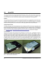
3.8 Power specifications
The drive receives DC power (+5V or +12V) through a native SATA power connector. See Figure 4 on page 24.
3.8.1 Power consumption
Power requirements for the drives are listed in the table on page 9. Typical power measurements are based on
an average of drives tested, under nominal conditions, using 5.0V and 12.0V input voltage at 25°C ambient
temperature.
• Spinup power
Spinup power is measured from the time of power-on to the time that the drive spindle reaches operating
speed.
• Seek mode
During seek mode, the read/write actuator arm moves toward a specific position on the disc surface and
does not execute a read or write operation. Servo electronics are active. Seek mode power represents the
worst-case power consumption, using only random seeks with read or write latency time. This mode is not
typical and is provided for worst-case information.
• Read/write power and current
Read/write power is measured with the heads on track, based on a 16-sector write followed by a 32-ms
delay, then a 16-sector read followed by a 32ms delay.
• Operating power and current
Operating power is measured using 40 percent random seeks, 40 percent read/write mode (1 write for each
10 reads) and 20 percent drive idle mode.
• Idle mode power
Idle mode power is measured with the drive up to speed, with servo electronics active and with the heads in
a random track location.
• Standby mode
During Standby mode, the drive accepts commands, but the drive is not spinning, and the servo and read/
write electronics are in power-down mode.

Constellation ES.2 Serial ATA Product Manual, Rev. E 9
Table 2: 3TB Drive DC power requirements
3.0Gb mode 6.0Gb mode
Voltage +5V +12V +5V +12V
Regulation ± 5% ± 5%
Avg Idle Current * 0.36 0.49 0.37 0.49
Advanced Idle Current *
Idle_A 0.15 0.50 0.16 0.50
Idle_B 0.13 0.41 0.14 0.41
Idle_C 0.13 0.24 0.14 0.24
Standby 0.13 0.01 0.14 0.01
Maximum Start Current
DC (peak DC)
3σ
0.54 2.05 0.54 2.06
AC (Peak DC)
3σ
0.70 3.01 0.73 2.85
Delayed Motor Start (DC max)
3σ
0.13 0.01 0.14 0.01
Peak operating current (random read):
Typical DC 0.32 0.75 0.33 0.75
Maximum DC
3σ
0.32 0.78 0.33 0.78
Maximum DC(peak)
3σ
1.13 1.83 1.18 1.81
Peak operating current (random write)
Typical DC 0.43 0.61 0.44 0.61
Maximum DC
3σ
0.44 0.63 0.45 0.63
Maximum DC(peak)
3σ
0.98 1.78 1.00 1.78
Peak operating current (sequential read)
Typical DC 0.64 0.48 0.65 0.48
Maximum DC
3σ
0.66 0.50 0.67 0.50
Maximum DC(peak)
3σ
1.04 0.76 1.06 0.74
Peak operating current (sequential write)
Typical DC 0.73 0.48 0.74 0.48
Maximum DC
3σ
0.75 0.50 0.76 0.50
Maximum DC(peak)
3σ
1.03 0.76 1.01 0.88

10 Constellation ES.2 Serial ATA Product Manual, Rev. E
*During periods of drive idle, some offline activity may occur according to the S.M.A.R.T. specification, which may increase acoustic and
power to operational levels.
Table 3: 3TB Drive DC power requirements
3.0Gb mode 6.0Gb mode
Voltage +5V +12V +5V +12V
Regulation ± 5% ± 5%
Avg Idle Current * 0.37 0.40 0.37 0.40
Advanced Idle Current *
Idle_A 0.15 0.42 0.16 0.42
Idle_B 0.13 0.34 0.14 0.34
Idle_C 0.13 0.20 0.14 0.20
Standby 0.12 0.01 0.13 0.01
Maximum Start Current
DC (peak DC)
3σ
0.57 2.11 0.57 2.11
AC (Peak DC)
3σ
0.80 2.84 0.72 2.79
Delayed Motor Start (DC max)
3σ
0.12 0.01 0.13 0.01
Peak operating current (random read):
Typical DC 0.40 0.70 0.40 0.69
Maximum DC
3σ
0.40 0.73 0.41 0.72
Maximum DC(peak)
3σ
1.14 1.83 1.15 1.76
Peak operating current (random write)
Typical DC 0.42 0.55 0.42 0.54
Maximum DC
3σ
0.43 0.57 0.43 0.56
Maximum DC(peak)
3σ
1.02 1.73 1.03 1.84
Peak operating current (sequential read)
Typical DC 0.72 0.41 0.72 0.40
Maximum DC
3σ
0.75 0.43 0.75 0.42
Maximum DC(peak)
3σ
1.07 0.80 1.09 0.99
Peak operating current (sequential write)
Typical DC 0.77 0.41 0.77 0.40
Maximum DC
3σ
0.80 0.43 0.80 0.42
Maximum DC(peak)
3σ
1.07 0.87 1.08 0.81

Constellation ES.2 Serial ATA Product Manual, Rev. E 11
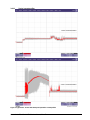
3.8.1.1 Typical current profiles
Figure 1. Typical 3TB - 5V and 12V startup and operation current profiles

12 Constellation ES.2 Serial ATA Product Manual, Rev. E
Figure 2. Typical 2TB - 5V and 12V startup and operation current profiles

Constellation ES.2 Serial ATA Product Manual, Rev. E 13
3.8.2 Conducted noise
Input noise ripple is measured at the host system power supply across an equivalent 80-ohm resistive load on
the +12 V line or an equivalent 15-ohm resistive load on the +5V line.
• Using 12V power, the drive is expected to operate with a maximum of 120mV peak-to-peak square-wave
injected noise at up to 10MHz.
• Using 5V power, the drive is expected to operate with a maximum of 100mV peak-to-peak square-wave
injected noise at up to 10MHz.
Note. Equivalent resistance is calculated by dividing the nominal voltage by the typical RMS read/write
current.
3.8.3 Voltage tolerance
Voltage tolerance (including noise):
5V ± 5%
12V ± 5%
3.8.4 Power-management modes
The drive provides programmable power management to provide greater energy efficiency. In most systems,
you can control power management through the system setup program. The drive features the following
power-management modes:
• Active mode
The drive is in Active mode during the read/write and seek operations.
• Idle mode
The buffer remains enabled, and the drive accepts all commands and returns to Active mode any time disc
access is necessary.
• Standby mode
The drive enters Standby mode when the host sends a Standby Immediate command. If the host has set
the standby timer, the drive can also enter Standby mode automatically after the drive has been inactive for
a specifiable length of time. The standby timer delay is established using a Standby or Idle command. In
Standby mode, the drive buffer is enabled, the heads are parked and the spindle is at rest. The drive
accepts all commands and returns to Active mode any time disc access is necessary.
• Sleep mode
The drive enters Sleep mode after receiving a Sleep command from the host. In Sleep mode, the drive buf-
fer is disabled, the heads are parked and the spindle is at rest. The drive leaves Sleep mode after it
receives a Hard Reset or Soft Reset from the host. After receiving a reset, the drive exits Sleep mode and
enters Standby mode with all current translation parameters intact.
Power modes Heads Spindle Buffer
Active Tracking Rotating Enabled
Idle_a ID Biased Rotating Enabled
Idle_b Parked Rotating Enabled
Idle_c Parked Rotating at lower RPM Enabled
Standby Parked Stopped Enabled
Sleep Parked Stopped Disabled

14 Constellation ES.2 Serial ATA Product Manual, Rev. E
• Idle and Standby timers
Each time the drive performs an Active function (read, write or seek), the standby timer is reinitialized and
begins counting down from its specified delay times to zero. If the standby timer reaches zero before any
drive activity is required, the drive makes a transition to Standby mode. In both Idle and Standby mode, the
drive accepts all commands and returns to Active mode when disc access is necessary.
3.8.4.1 Extended Power Conditions - PowerChoice
TM
Utilizing the load/unload architecture a programmable power management interface is provided to tailor sys-
tems for reduced power consumption and performance requirements.
The table below lists the supported power conditions available in PowerChoice. Power conditions are ordered
from highest power consumption (and shortest recovery time) to lowest power consumption (and longest
recovery time) as follows: Idle_a power >= Idle_b power >= Idle_c power >= Standby_z power. The further you
go down in the table, the more power savings is actualized. For example, Idle_b results in greater power sav-
ings than the Idle_a power condition. Standby results in the greatest power savings.
Each power condition has a set of current, saved and default settings. Default settings are not modifiable.
Default and saved settings persist across power-on resets. The current settings do not persist across power-on
resets. At the time of manufacture, the default, saved and current settings are in the Power Conditions log
match.
PowerChoice is invoked using one of two methods
• Automatic power transitions which are triggered by expiration of individual power condition timers. These
timer values may be customized and enabled using the Extended Power Conditions (EPC) feature set using
the standardized Set Features command interface.
• Immediate host commanded power transitions may be initiated using an EPC Set Features "Go to Power
Condition" subcommand to enter any supported power condition. Legacy power commands Standby Imme-
diate and Idle Immediate also provide a method to directly transition the drive into supported power condi-
tions.
PowerChoice exits power saving states under the following conditions
• Any command which requires the drive to enter the PM0: Active state (media access)
• Power on reset
PowerChoice provides the following reporting methods for tracking purposes
Check Power Mode Command
• Reports the current power state of the drive
Identify Device Command
• EPC Feature set supported flag
• EPC Feature enabled flag is set if at least one Idle power condition timer is enabled
Power Condition Name Power Condition ID Description
Idle_a 81
H
Reduced electronics
Idle_b 82
H
Heads unloaded. Disks spinning at full RPM
Idle_c 83
H
Heads unloaded. Disks spinning at reduced RPM
Standby_z 00
H
Heads unloaded. Motor stopped (disks not spinning)
Page is loading ...
Page is loading ...
Page is loading ...
Page is loading ...
Page is loading ...
Page is loading ...
Page is loading ...
Page is loading ...
Page is loading ...
Page is loading ...
Page is loading ...
Page is loading ...
Page is loading ...
Page is loading ...
Page is loading ...
Page is loading ...
Page is loading ...
Page is loading ...
Page is loading ...
Page is loading ...
Page is loading ...
Page is loading ...
Page is loading ...
Page is loading ...
Page is loading ...
Page is loading ...
Page is loading ...
Page is loading ...
Page is loading ...
Page is loading ...
Page is loading ...
Page is loading ...
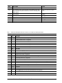
-
 1
1
-
 2
2
-
 3
3
-
 4
4
-
 5
5
-
 6
6
-
 7
7
-
 8
8
-
 9
9
-
 10
10
-
 11
11
-
 12
12
-
 13
13
-
 14
14
-
 15
15
-
 16
16
-
 17
17
-
 18
18
-
 19
19
-
 20
20
-
 21
21
-
 22
22
-
 23
23
-
 24
24
-
 25
25
-
 26
26
-
 27
27
-
 28
28
-
 29
29
-
 30
30
-
 31
31
-
 32
32
-
 33
33
-
 34
34
-
 35
35
-
 36
36
-
 37
37
-
 38
38
-
 39
39
-
 40
40
-
 41
41
-
 42
42
-
 43
43
-
 44
44
-
 45
45
-
 46
46
-
 47
47
-
 48
48
-
 49
49
-
 50
50
-
 51
51
-
 52
52


Seagate 2TB SATA 3.5" User manual
- Category
- Internal hard drives
- Type
- User manual
Ask a question and I''ll find the answer in the document
Finding information in a document is now easier with AI
Related papers
-
Seagate User manual
-
Seagate Self-Encrypting Drive User guide
-
-
-
-
-
-
-
-