Kenmore 153336150 User manual
- Category
- Water heaters & boilers
- Type
- User manual

I
SWARS
Owners
Manual
FOR POTABLEWATER
HEATING ONLY
NOT SUITABLEFOR
SPACEHEATING
NOT FOR USE IN
MOBILE HOMES
Model No.
153.336150 30 Gal.
153.336250 40 Gal.
153,33631I 30 Gal, High Altitude
t53,336350 30 Gal.
153.336411 40 Gal. High Altitude
153.336450 40 Gal.
153.33651I 50 Gal. High Altitude
153.336550 50 Gal,
153.336750 30 GaL Propane (L.R)
153.3368I l 40 Gal. Propane (LP.)
High Altitude
153.336850 40 Gal, Propane (L,P)
Caution:
Read and Follow
All Safety Rules and
Operating Instructions
Before First Use of
This Product.
Save this Manual for Future Reference.
POWER MlSER 6
GAS WATER HEATER
• Safety Instructions
• Installation
• Operation
For Your Safety
AN ODORANT iS ADDED TO THE GAS USED BY THIS
WATER HEATER
• Care and Maintenance
• Troubleshooting
• Parts List
WARNING: if the information in these instructions are not fol-
lowed exactly, a fire or explosion may result, causing property
damage, personal injury or death.
-Do not store or use gasoline or other flammable vapors and liquids
in the vicinity of this or any other appliance.
-WHAT TO DO IF YOU SMELL GAS
• Do not try to light any appliance.
, Do not touch any electrical switch; do not use any phone in your
building.
• Immediately call your gas supplier from a neighbor's phone.
Follow the gas supplier's instructions.
° If you can not reach your gas supplier, call the fire department.
-Installation and service must be performed by a qualified installer,
service agency or the gas supplier.
AWARNING
Improper installation, adjustment, alteration, servlce or maintenance can
cause DEATH, SERIOUS BODILY INJURY,OR PROPERTY DAMAGE. Refer to
this manual for assistanceor consult the local Sears Service Center or gasutil-
ity for further nformation.
_WARNING
Flammable vapors may be drawn by air currents from other areas of the
structure to this appliance.
AWARNING
READ THE GENERAL SAFETY SECTION BEGINNING ON INSIDE COVER
AND THEN THIS ENTIRE MANUAL BEFORE INSTALLING OR OPERAT-
ING THIS WATER HEATER.
Sears, Roebuck and Co., Hoffman Estates, IL 60179 U.S.A.

Safety
recautions
_WARNING
Improper installation, adjustment, a|teration, service or
maintenance can cause DEATH, SERIOUS BODILY
INJURY, OR PROPERTY DAMAGE. Refer to this manu-
al for assistance or consult your local Sears Service
Center for further information.
AWARNING
WATER HEATERS EQUIPPED FOR ONE TYPE GAS
ONLY: This water heater is equipped for one type gas
only. Check the model rating plate near the gas control
valve for the correct gas. DO NOT USE THIS WATER
HEATER WITH ANY GAS OTHER THAN THE ONE
SHOWN ON THE MODEL RATING PLATE. Failure to
use the correct gas can cause problems which can result in
DEATH, SERIOUS BODILY INJURY, OR PROPERTY
DAMAGE. if you have any questions or doubts consult
your gassupplier or local utility.
AWARNING
INSTALLATIONS IN AREAS WHERE FLAMMABLE LIQ-
UIDS (VAPORS) ARE LIKELY TO BE PRESENT OR
STORED (GARAGES, STORAGE, AND UTILITY AREAS,
ETC): Flammable tiquids (such as gasoline, solvents,
propane (LP) or butane, etc.), all of which emit flammable
vapors, may be improperly stored or used in such areas.
The gas water heater pilot light or main burner can ignite
such vapors. The resulting flashback and fire can cause
death or serious burns to anyone in the area, as well as
property damage.
If installation in such areas is your only option, then the
installation must be accomplished in a way that the pilot
flame and main burner flame are elevated from the floor
_t least 18 inches. While this may reduce the chances of
flammable vapors from a floor spill being ignited, gasoline
and other flammable substances should never be stored or
used in the same room or area containing a gas water
heater or other open flame or spark producing appliance.
NOTE: Flammable vapors may be drawn by air currents
from other areas of the structure to the appliance.
_WARNING
If this water heater will be used in beauty shops, barber
shops, cleaning establishments, or self-service laundries
with dry cleaning equipment, it is imperative that the
water heater or water heaters be installed so that com-
bustion and ventilation air be taken from outside these
areas. Refer to the "Locating The New Water Heater"
section of this manual and also the latest edition of the
National Fuel Gas Code, ANS! Z223.1, also referred to as
NFPA 54 for specifics provided concerning air required.
AWARNING
A fire can start if combustible materials such as clothing,
cleaning materials, or flammable liquids are placed against
or next to the water heater.
_WARNING
At the time of manufacture this water heater was pro-
vided with a combination temperature-pressures relief
valve certified by a nationally recognized testing labora-
tory that maintains periodic inspection of production of
listed equipment or materials, as meeting the require-
ments for Relief Valves and Automatic Gas Shutoff
Devices for Hot Water Supply Systems, and the latest
edition of ANSI Z21.22 and the code requirements of
ASME. If replaced, the valve must meet the require-
ments of local codes, but not less than a combination
temperature and pressure relief valve certified as meet-
ing the requirements for Relief Valves and Automatic
Gas Shutoff Devices for Hot Water Supply Systems,
ANSI Z21.22 by a nationally recognized testing laborato-
ry that maintains periodic inspection of production of
listed equipment or materials.
The valve must be marked with a maximum set pressure
not to exceed the marked hydrostatic working pressure
of the water heater (I 50 Ibs./sq. in.) and a discharge
capacity not less than the water heater input rate as
shown on the model rating plate. (Electric heaters -
watts divided by 1000 x 3415 equal BTU/Hr. rate.)
Your local jurisdictional authorlty_ while mandating the
use of a temperature-pressure relief valve complying
with ANSI Z21.22 and ASME, may require a valve model
different from the one furnished with the water heater.
Compliance with such local requirements must be satis-
fied by the installer or end user of the water heater with
a locally prescribed temperature-pressure relief valve
installed in the designated opening in the water heater in
_lace of the factory furnished valve.
For safe operation of the water heater, the relief valve
must not be removed from it's designated opening or
plugged.
The temperature-pressure relief valve must be installed
directly into the fitting of the water heater designated for
the relief valve. Position the valve downward and provide
tubing so that any discharge will exit only within 6 inches
above, or at any distance below the structural floor. Be
certain that no contact is made with any live electrical
part. The discharge opening must not be blocked or
reduced in size under any circumstances. Excessive
length, over 30 feet, or use of more than four elbows can
cause restriction and reduce the discharge capacity of
the valve.
No valve or other obstruction is to be placed between
the relief valve and the tank. Do not connect tubing
directly to discharge drain unless a 6" air gap is provided.
To prevent bodily injury, hazard to llfe, or property dam-
age, the relief valve must be allowed to discharge water
in quantities should circumstances demand, if the dis-
charge pipe is not connected to a drain or other suitable
means, the water flow may cause property damage.
The Discharge Pipe:
• Must not be smaller in size than the outlet pipe size of
the valve, or have any reducing couplings or other
restrictions.
• Must not be plugged or blocked.
• Must be of material listed for hot water distribution.
• Must be installed so as to allow complete drainage of
both the temperature-pressure relief valve, and the_"
discharge pipe. I
• Must terminate at an adequate drain.
• Must not have any valve between the relief valve and
tank.

Safety Precautions
AWARNING
A gas water heater cannot operate properly without the
correct amount of air for combustion. Do not install in a
confined area such a closet, unless you provide air as
shown in the "Locating The New Water Heater" section.
Never obstruct the flow of ventilation air. If you have any
doubts or questions at all, call your gas company. Failure
to provide the proper amount of combustion air can result
in a fire or explosion and can cause DEATH, SERIOUS
BODILY INJURY, OR PROPERTY DAMAGE.
_,WARNING
This water heater must not be installed directly on car-
peting. Carpeting must be protected by a metal or wood
panel beneath the appliance extending beyond the full
width and depth of the appliance by at least 3 inches
(76.2mm) in any direction, or if the appliance is installed
in an alcove or closet, the entire floor must be covered by
the panel. Failure to heed this warning may result in a
fire hazard.
_WARNING
HOTTER WATER CAN SCALD: Water heaters are
intended to produce hot water. Water heated to a tem-
perature which will satisfy clothes washing, dish washing,
and other sanitizing needs can scald and permanently
injure you upon contact. Some people are more likely to
be permanently injured by hot water than others. These
include the elderly, children, the infirm, or physically/men-
tally handicapped. If anyone using hot water in your home
fits into one of these groups or if there is a local code or
state law requiring a certain temperature water at the hot
water tap, then you must take special precautions. In addi-
tion to using the lowest possible temperature setting that
satisfies your hot water needs, a means such as a mixing
valve, should be used at the hot water taps used by these
oeople or at the water heater. Mixing valves are available
: plumbing supply or hardware stores. Follow manuFac-
.urers instructions for installation of the valves. Before
l changing the factory setting on the thermostat, read the
"Temperature Regulation" section in this manual.
AWARNING
Soot build-up indicates a problem that requires correc-
tion before further use. Turn "off" gas to water heater
and leave "off" until repairs are made, because Failure to
correct the cause of the sooting can result in a fire or
explosion causing DEATH, SERIOUS BODILY INJURY,
OR PROPERTY DAMAGE.
I
&WARNING
VENT DAMPERS - Any vent damper, whether it isoperat-
ed thermally or otherwise must be removed if its use
inhibits proper drafting of the water heater.
Thermally Operated Vent Dampers: Gas-fired water
heaters having thermal efficiency in excess of 80% may
produce a relatively low flue gas temperature. Such tem-
peratures may not be high enough to properly open ther-
mally operated vent dampers. This would cause spillage of
flue gasesand may cause carbon monoxide poisoning.
Vent dampers must bear evidence of certification as com-
plying with the latest edition of American National
Standard ANSI Z21.68 (ANSI Z21.66 & 67, respectively,
cover electrically and mechanically actuated vent
dampers). Before installation of any vent damper, consult
your local Sears Service Center or the gas utility for fur-
ther information.
AWARNING
• The appliance and its individual shutoff valve must be dis-
connected from the gas supply piping system during any
pressure testing of the gas system at test pressures in
excess of I/2 pound per square inch (3.SEPa).
• The appliance must be isolated from the gas supply pip-
ing system by closing its individual manual shutoff valve
during any pressure testing of the gas supply piping sys-
tem at test pressures equal or less than I/2 pound per
square inch (3.5kPa),
_WARNING
BEFORE LIGHTING [PROPANE (L.P.) GAS WATER
HEATERS]: Propane (LR) gas is heavier than air. Should
there be a leak in the system, the gas will settle near the
ground. Basements, crawl spaces, skirted areas under
mobile homes (even when ventilated), closets and areas
below ground level will serve as pockets for the accumula-
tion of this gas. Before attempting to light or rellght the
water heater's pilot or turning on a nearby electrical light
switch, be absolutely sure there is no accumulated gas in
the area. Search for odor of gas by sniffing at ground level
......the vicinity of the appliance. If odor is detected, follow
_eps ndicated at "For Your Safety" on the cover page of
this manual then leave the premises.
_,WARNING
Chemical vapor corrosion of the flue and vent system
may occur if air for combustion contains certain chemical
vapors. Spray can propellants, cleaning solvents_ refrigera-
tor and air conditioner refrigerants, swimming pool
chemicals, calcium and sodium chloride, waxes, bleach,
and process chemicals are typical compounds which are
potentially corrosive.
AWARNING t
Obstructed or deteriorated vent systems may present a
serious health risk or asphyxiation.
Safety Precautions continued on page 4
3

Safety Precautions
AWARNING
The water heater with draft hood installed must be prop-
erly vented to a chimney which terminates outdoors.
Never operate the water heater unless it is vented to the
outdoors and has adequate air supply to avoid risks of
improper operation, explosion or asphyxiation.
_WARNING
Hinlmum clearances between the water beater and com-
bustible construction are I" at the sides and rear, 4" at the
front, and 6" from the vent pipe. Clearance from the top of the
jacket is 18"on most models. Note that a lesserdimension may
be allowed on some models. Refer to the label on the water
heater adjacent to the gascontrol valve for all clearances.
_CAUTION
WATER HEATERS EVENTUALLY LEAK: Installation ol
the water heater must be accomplished in such a manner
that if the tank or any connections should leak, the flow of
water will not cause damage to the structure. When such
locations cannot be avoided, a suitable drain pan should
be installed under the water heater. Drain pans are avail-
able at your local Sears store. Such a drain pan must be
not greater than I |/2 inches deep, have a minimum
length and width of at least 2 inches greater than the
water heater dimensions and must be piped to an ade-
quate drain. The pan must not restrict combustion air
flow. Under no circumstances is the manufacturer or
Sears to be held liable for any water damage in connec-
tion with this water heater.
I ,_WARNING t
Do not use this appliance if any part of it has been under I
water. Immediately call a Sears Service Technician to I
inspect the appliance and to replace the gascontrol or any I
part of the burner system which has been under water. I
AWARNING
HYDROGEN GAS: Hydrogen gas can be produced in a hot
water system that has not been used for a long period of
time (generally two weeks or more). Hydrogen gas is
extremely flammable and explosive. To prevent the possi-
bUity of injury under these conditions_ we recommend the
hot water faucet be opened for several minutes at the
kitchen sink before any electrical appliances which are
connected to the hot water system are used (such as a dis-
_washer or washing machine). If hydrogen gas is present,
there will probably be an unusual sound similar to air
escaping through the pipe as the hot water faucet is
opened. There must be no smoking or open flame near
the faucet at the time it isopen.
_WARNING
INSULATING JACKETS: When installing an external
water heater insulation jacket on a gas water heater:
• DO NOT cover the temperature-pressure relief valve.
• DO NOT put insulation over any part of the top of the
gaswater heater.
• DO NOT put insulation over the gas control valve or gas
control valve/burner cover, or any access areas to the
burner.
• DO NOT let insulation around the gas water heater to
get within 8 inches of the floor (air must get to the
burner).
• DO NOT cover or remove operating instructions, and
safety related warning labels and materials affixed to the
water heater.
Failure to heed this will result in the possibility of a fire or
explosion.

Table of Contents
_al_y¢_'_"Precautions ............................................................................................................................................ 24
Table of Contents ................................................................................................................................................5
Customer Responsibilities .......................................................................................................................6
Product Specifications ..................................................................................................................................6
Materials and Basic Tools Needed ...............................................................................................7
Materi_s Needed ...................................................................................................................................................................... 7
Basic Tools ................................................................................................................................................................................ 7
Installation Instructions ........................................................................................................................8-16
Removing the Old \Vater Heater ............................................................................................................................................... 8
Facts to Consider About the Location ....................................................................................................................................... 9
Combustion Air and Ventilation for Appliances in Unconfined Spaces ................................................................................... 10
Combustion Air and Ventilation for Appliances in Confined Spaces....................................................................................... 10
Water Piping ........................................................................................................................................................................... t 1
Temperature-Pressure Relief Valve........................................................................................................................................... 12
Filling the Water Heater .......................................................................................................................................................... 13
Venting .............................................................................................................................................................................. 13-14
Gas Piping ......................................................................................................................................................................... 14-15
Installation Checklist .............................................................................................................................................................. 16
OperatinR Instructions .........................................................................................................................I7-19
Eighting ............................................................................................................................................................................. 17-!8
Temperature Regulation .......................................................................................................................................................... 19
_ervice and Adjustment ...................................................................................................................... 20-21
Tank (Sediment) Cleaning ...................................................................................................................................................... 20
Venting System Inspection ...................................................................................................................................................... 20
Burner Inspection ................................................................................................................................................................... 20
Burner Cleaning ..................................................................................................................................................................... 20
L.P. Gas Control Valve & Burner Assembly ............................................................................................................................ 20
Draining ................................................................................................................................................................................. 21
Temperature-Pressure Relief ValveOperation .......................................................................................................................... 21
Drain VaJveWasher Replacement ........................................................................................................................................... 21
Housekeeping ......................................................................................................................................................................... 2 !
Service .................................................................................................................................................................................... 21
Troubleshooting Guide ........................................................................................................................22-25
Start Up Conditions .......................................................................................................................................................... 22-23
Thermal F_xpansion.............................................................................................................................................................. 22
Strange Sounds ..................................................................................................................................................................... 22
Condensation ....................................................................................................................................................................... 23
Smoke/Odor ......................................................................................................................................................................... 23
Operational Conditions ..................................................................................................................................................... 23-24
Smelly Water ........................................................................................................................................................................ 23
"Air" in Hot \rater Faucets ................................................................................................................................................... 23
High Temperature Shut Off System...................................................................................................................................... 24
Not Enough Hot Water ........................................................................................................................................................ 24
Water is too Hot ................................................................................................................................................................... 24
.... Leakage Checkpoints .............................................................................................................................................................. 25
tarts Order List............................................................................................................................................... 28-31

Customer
ponsibilities
,-,-ILlnanK You for purchasing a Sears water heater.
Properly installed and maintained, it should give you years of
trouble free service. If you should decide that you want the new
water heater professionally installed by Sears call the local Sears
Service Center or aW Sears store. They will arrange for prompt,
quality installation by Sears authorized contractors.
Abbreviations Found In This Instruction Manual
A.G.A. - American Gas Association
A.N.S.L -American National Standards Institute
AWARNING
This gas-fired water heater is design certified by the
American Gas Association Laboratories under American
National Standardsfor Gas Water Heaters, The installa-
tion must conformwith this manual,LocalCodesandwith
the latest edition of the National Fuel Gas Code, ANS!
Z223.I.
Thispublicationisavailablefrom your localgovernmentor
public library, gas company, or by writing NFPA,
Batterymarch Park,Quincy,MA 02269.
• Read the "Safety Precautions" section, pages 2 through 4 of
this manual first and then the entire manual carefnll)_ If you
don't follow the safety rules, the water heater will not operate
properly. It could cause DEATH, SERIOUS BODILY
INJURY AND/OR PROPERTY DAMAGE.
• This manual contains instructions for the installation, op£
tion, and maintenance of the gas-fired water heater. It also
contains warnings through out tile manual that you must read
and be aware of, All warnings and ali instructions are essential
to the proper operation of the water heater and your safety.
Since we cannot put everything on the first few pages, READ
THE ENTIRE MANUAL BEFORE ATTEMPTING TO
INSTALL OR OPERATE THE WATER HEATER.
• The installation must confbrm with the instructions in this
manual; gas company rules; and Local Codes, or in the
absence of Local Codes, with the latest edition of the National
Fuel Gas code, ANSI Z223.1, also referred to as NFPA 54.
This publication is available from your local government or
public library or gas company or by writing NFPA,
gatterymarch Park, Quincy, MA 02269.
• If after reading this manual you have any questions or do not
understand any portion of the instructions, call the Sears
Service Center.
• Carefillly plan the place where you are going to put the water
heater. Correct combustion, vent action, madvent pipe instal-
lation are very important in preventing death from possible
carbon monoxide poisoning and fires.
Examine the location to ensure the water heater complies with
the "Facts to Consider About the Location" section in this
manual,
o For California installation this water heater must be braced,
anchored, or strapped to avoid falling or moving during an
earthquake. See instructions for correct installation proce-
dures. Instructions may be obtained from your local dealer,
wholesaler, public utilities or California Office of the State
Architect, 400 P Street, Sacramento, CA 95814.
roduct Specifications
MODEL NUMBER
153.336150
153.336250
153.33631i
153.336350
153.336411
153.336450
153.336511
153.336550
153.336750
153.336811
153.336850
'lANK
CAPACITY
INGALLONS
30
40
30
30
40
40
50
50
30
40
40
TYPE
OF
GAS
NATURAL
NATURAL
NATURAL
NATURAL
NATURAL
NATURAL
NATURAL
NATURAL
PROPANE (L.P,
PROPANE (L.P.)
PROPANE (L.P.)
B.ZU.
RATE
30,000
35,000
33,500
33,500
35,500
35,500
35,5OO
35,500
33,500
35,500
35,50O
RECOVERY
RATEGALS.
PERHOUR @
90°FRISE
30,7
35.8
34.3
34.3
36.3
36.3
36.3
36.3
34.3
36.3
36.3
MINIMUM
VENT
PIPE
3" or 4"
3" or 4"
3"
3"
3"
3"
3"
3"
3"
3"
3"
DIMENSIONSININCHES
HEIGHTTO
DIAMETER JACKETTOP
18 47
2O 47_
16 56
16 56
18 56_
t8 56_
20 56_
20 56_
16 56
t8 56_
t8 56_

ateriais and Basic Tools Needed
Materials Needed
To simplify the installation Sears has available the installation
parts shown below. You may or may not need all of these materi-
als, depending on your type of installation.
Water Heater _ i
Installation _ i
i Kit
WATER HEATER INSTAL-
LATION KIT WITH FLEXI-
BLE CONNECTORS FOR
k
314" OR 1/2" THREADED
OR COPPER PLUMBING
O
VENT ELBOW
EXPANSION TANKS
FOR THERMAL
EXPANSION CONDI-
TIONS AVAILABLE IN
2 GALLON AND 5
GALLON CAPACITY
THROUGH LOCAL
SEARS STORE OR
SERVICE CENTERS
FLEXIBLE WATER
HEATER GAS CON-
NECTOR WITH
FITTINGS
VENT PIPE
WATER HEATER H EAT
TRAPS HELP REDUCE HEAT
LOSS DUE TO THERMAL
SYPHONING
WATER HEATER STAND 24"x24"x18"
FOR USE WITH WATER HEATERS
INSTALLED IN RESIDENTIAL
GARAGES HAVING A DIAMETER 24"
OR LESS AND A RATED CAPACITY 75
GALLONS OR LESS
DRAIN PANS
AVAILABLE IN 20" DIAMETER FOR
WATER HEATERS HAVING A DIAME-
TER 18" OR LESS AND AVAILABLE IN
28" DIAMETER FOR WATER HEATERS
HAVING A DIAMETER 26" OR LESS
Basic Tools
You may or may not need all of these tools, depending on your
type of installation. These tools can be purchased at your locaI
Sears store.
• Pipe Wrenches (2) 14"
• Screwdriver
• Tin Snips
• 6 Foot Tape of Folding Rule
• Garden Hose
• Drill
° Pipe dope or Teflon Tape
GARDEN HOSE 6 FOOT TAPE
SLOT-HEAD SCREWDRIVER
PiPE
WRENCH
PHiLLiPS SCREWDRIVER
ROLL OF TEFLON TAPE
(USE ONLY ON WATER
CONNECTIONS)
PIPE DOPE (SQUEEZE TUBE)
(USE FOR WATER AND
GAS CONNECTIONS)
TIN SNIPS
ADDITIONAL TOOLS NEEDED
WHEN SWEAT SOLDERING
• Tubing Cutters or Hacksaw
• Propane Torch
• So_ Solder
• Solder Flux
• EmeryCloth
• Wire Brushes
HACKSAW
314" WIRE BRUSH
112"WIRE BRUSH
ROLL OF LEAD FREE
SOFT SOLDER
ROLL OF EMERY
CLOTH
SOLDER FLUX
PROPANE
TORCH
TUBING
CUTTER

Installation Instructions
Removing the Old Water Heater
Turn "OFF" the gas supply to the water heater,
_WARNING
If the main gas line shutoff serving all gas appliancesis
used,also shut "OFF" the gasat eachappliance.Leaveall
gasappliancesshut "OFF" until the water heater installa-
tion iscomplete.
Turn "OFF" the water to the water
heater, Some installations require that
the water be turned off to the entire
house.
('_Check again to make sure the gas supply
_Jis OFF to the water heater. Then dis- __
connect the gas supply connection from
the gas control valve, "
A
Attach a hose to the water heater drain
valve and put the other end in a floor
drain or outdoors. Open the water heater
drain valve. Open a nearby hot water
_ucet which will relieve pressure in the
water heater and speed draining.
Disconnect the vent pipe from the draft hood where
they connect to the water heater. In most installations
the vent pipe can be lifted off after any screw or other
attached devices are removed. Dispose of the draft
hood. The new water heater has the draft hood which
must be used for proper operation.
a.
If you have copper piping to the water
heater, the two copper water pipes can
be cut with a hacksaw approximately
four inches away from where they con-
nect to the water heater, This will avoid
cutting off the pipes too short.
Additional cuts can be made later if nec-
essary. Disconnect the temperature-pres_
sure retief valve drain line. When the
water heater is drained, disconnect the
hose from the drain valve. Close the
drain valve, The water beater is now
completely disconnected and ready to be
removed.
b,
If you have galvanized pipe to the water
heater, loosen the two galvanized pipes
with a pipe wrench at the union in each
line. Also disconnect the piping remain-
ing to the water heater. These pieces
should be saved since they may be need-
ed when reconnecting the new water
heater. Disconnect the temperature_pres-
sure relief valve drain line. When the
water heater is drained, disconnect the
hose from the drain valve. Close the
drain valve. The water heater is now
completely disconnected and readym be
removed.
AWARNING I
The water passingout ofthe drainvalvemay beextremely I
hot. To avoidbeingscalded,make sure all connectionsare
tight and that the water flow is directed away from any
person.
_CAUTION I
Mineral buildupor sedimentmay haveaccumulatedin the I
oldwater heater.Thiscausesthe water heater to be much !
heavierthan normal and this residue, if spilledout, could
causestaining.

Installation Instructions (cont'd)
--acts to Consider About the
Location
You should carefully choose an indoor location for the new
water heater, because the placement is a very important consid-
eration _br the safety of the occupants in the building and for
the most economical use of the appliance. This water heater is
not for use in mobile homes or outdoor installation.
Whether replacing an old water heater or putting the water
heater in a new location, the following critical points must be
observed.
o The location selected should be indoors as c!ose as practical to
the gas vent or chimney to which the water heater vent is
going to be connected, and as centralized with the water pip-
ing system as possible. The water heater, as all water heaters,
will eventually leak. Do not install without adequate drainage
provisionswhere water flow will cause damage.
ACAUTION
WATER HEATERS EVENTUALLY LEAK: Installation of the
water heater must be accomplished in such a manner that if
the tank or any connections should leak, the flow of water will
not cause damage to the structure. When such locations can.
not be avoided, a suitable drain pan should be installed under
the water heater. Drain pans are available at your local Sears
store. Such a drain pan must be not greater than 1½ inches
deep, have a minimum length and width of at least 2 inches
greater than the water heater dimensions and must be piped
to an adequate drain. The pan must not restrict combustion air
flow. Under no circumstances isthe manufacturer or Searsto
be held liable for any water damage in connection with this
water heater.
AWARNING
INSTALLATIONS IN AREAS WHERE FLAHHABLE LIQUIDS
(VAPORS) ARE LIKELY TO BE PRESENT OR STORED
(GARAGES, STORAGE, AND UTILITY AREAS, ETC):
Flammable liquids(such as gasoline,solvents,propane (LP) or
butane, etc.), all of which emit flammable vapors, may be
improperly stored or used in such areas. The gaswater heater
pilot light or main burner can ignite suchvapors. The resulting
flashbackand fire cancausedeath or seriousburns to anyone in
the area, aswell asproperty damage.
If installation in suchareasisyour onlyoption, then the installa-
tion must be accomplished in a way that the pilot flame and
main burner flame are elevated from the floor at least 18inches.
While this may reduce the chancesof flammable vapors from a
floor spillbeing ignited,gasolineand other flammable substances
shouldnever be stored or used in the same room or area con-
raining a gaswater heater or other open flame or spark produc-
ingappliance.
NOTE: Flammable vapors may be drawn by air currents from
other areasofthe structure to the appliance.
[ AWARNING
Propellants of aerosol spraysand volatile compounds, (clean-
ers, chlorine based chemicals, refrigerants, etc.) in addition to
being highlyflammable in many cases, will also change to cor-
rosive hydrochloric acid when exposed to the combustion
products of the water heater. The results can be hazardous,
and also causeproduct failure.
• The location selection must provide adequate clearances for ser-
vicing and proper operation of the water heater.
AWARNING
This water heater must not be installed directly on carpeting.
Carpeting must be protected by a metal or wood panel
beneath the appliance extending beyond the full width and
depth of the appliance by at least 3 inches (76.2mm) in any
direction, or if the appliance is installed in an alcove or closet,
the entire floor must be covered by the panel. Failure to heed
this warning may result ina fire hazard.
AWARNING
Minlmum clearances between the water heater and com-
bustible construction are I" at the sides and rear, 4" at the
front, and 6" from the vent pipe. Clearance from the top of the
jacket is 18"on most models. Note that a lesserdimension may
be allowed on some models. Refer to the label on the water
heater adjacent to the gascontrol valve for all clearances.
f2" MAX.
f
VENTILATION
AIR
OPENINGS O
6'_MI_--
FRONT VI_
OF DOOR
I Figure I
'11,MIN. _]_=_L] 4' HtN"
TOP VIEW
OF CLOSET TOP VIEW I" HIN,
WITHOUT DOOR OF CLOSET
_;' HAX, WITH DOOR
A_R DUCT
AWARNING
A gaswater heater cannot operate properly without the cor-
rect amount of air for combustion. Do not install in a confined
area sucha closet, unlessyou provide air as shown inthe "Facts
to Consider About the Location" section. Never obstruct the
flow of ventilation air. If you have any doubts or questionsat all,
call your gascompany. Failure to providethe proper amount of
combustion air can result in a fire or explosion and can cause
DEATH, SERIOUS BODILY INJURY,OR PROPERTY DAHAGE.
AWARNING
If this water heater will be usedin beauty shops,barber shops,
cleaning establishments, or self-service laundries with dry
cleaning equipment, it is imperative that the water heater or
water heaters be installed so that combustion and ventilation
air be taken from outside these areas. Refer to the "Facts to
Consider About the Location" section ofthis manual and also
the latest edition of the National Fuel Gas Code, ANSI Z223.1,
also referred to as NFPA 54 for specificsprovided concerning
air required, i

Installation Instructions (cont'd)
Combustion Air and Ventilation
for Appliances Located in
Unconfined Spaces
Unconfined Space is a space whose volume is not less than 50
cubic feet per 1,000 Btu per hour of the aggregate input rating
of all appliances installed in that space. Rooms communicating
directly with the space in which the appliances are installed,
through openings not furnished with doors, are considered a
part of the unconfined space
In unconfined spaces in buildings, infiltration may be adequate
to provide air for combustion, ventilation and dilution of flue
gases. However, in buildings of tight construction (for example,
weather stripping, heavily insulated, caulked, vapor barrier, etc.),
additional air may need to be provided using the methods
described in Combustion Air and Ventilation for Appliances
Located in Confined Spaces, b.
Combustion Air and Ventilation
for Appliances Located in
Confined Spaces
Confined Space is a space whose volume is less than 50 cubic
feet per 1,000 Btu per hour of the aggregate input rating of all
appliances installed in that space.
a. ALL AIR FROM INSIDE BUILDINGS:
(See Page 8 Figure 1, and Figure 2 below)
The confined space shall be provided with two permanent
openings communicating directly with an additional room(s)
of sufficient volume so that the combined volume of all
spaces meets the criteria for an unconfined space. The total
input of all gas utilization equipment installed in the com-
bined space shall be considered in making this determination.
Each opening shall have a minimum flee area of one square
inch per 1,000 BTU per hour of the total input rating of all
gas utilization equipment in the confined space, but not less
than 100 square inches. One opening shall commence within
12 inches of the top nod one commencing within 12 inches
of the bottom of the enclosure.
I Figure 2 I
8 VENT
F_RNAC.E OPENINGS
Ill i _ _
b. ALL AIR FROM OUTDOORS: (seeFigures 3-5)
The confined space shall be provided with two permanent
openings, one commencing within 12 inches of the top and
one commencing within 12 inches f?om the bottom of the
enclosure. The openings shall communicate directly, or by
ducts, with the outdoors or spaces (crawl or attic) that freely
communicate with the outdoors.
CHIMR_ OR GAg V_NT
VENTILATION LOUVER8
J_LT INLETAIN VENTILATIONLOHVENS
1. When directly communicating with the outdoors, each open-
ing shall have a minimum free area of 1 square inch per 4,000
BTU per hour of total input rating of all equipment in the
enclosure. (See Figure 3.)
2. When communicating with the outdoors through vertical
ducts, each opening shall have a minimum free area of 1
square inch per 4,000 BTU per hour of total input rating of
all equipment in the enclosure. (See Figure 4.)
Figure 4 ]
CHIMNEY OFt _AS VENT
VENTILATION LOUVERS
(eachend o_a_tic)
TLET
WATER HEATE FI
FUFtN,a.CE
INLET AJR DLFCT
a_ov_ floor_
3. When communicating with the outdoors through horizontal
ducts, each opening shall have a minimum free area of !
square inch per 2,000 BTU per hour of total input rat ng oF
all equipment in the enclosure. (See Figure 5.)
Figure 5 ]
_ GHIMNEY Ofl GAS VE I
WATFFI _ OUTLET AIF_DUCT
%'&
_ INLET A_F_DUCT
4. \Vhen ducts are used, they shall be of the same cross-sectional
area as the free area of the openings to which they connect.
The minimum short side dimension of rectangular air ducts
shall not be less than 3 inches. (See Figure 5.)
10
,
.
Louvers and Grilles: In calculating free area, consideration
shall be given to the blocking effect of louvers, grilles or
screens protecting openings. Screens used shall not be smaller
than 5_inch mesh. If the f?ee area through a design of louver
or grille is known, it should be used in calculating the size
opening required to provide the free area specified. If the
design and free area is not lmown, it may be assumed that
wood louvers wil! be 20-25 percent free area and metal louvers
and grilles will have 60-75 percent free area. Louvers and
grilles shall be fixed in the open position or interlocked with
the equipment so that they are opened automatically during
equipment operation.
Special Conditions Created by Mechanical Exhausting or
Fireplaces: Operation of exhaust fans, ventilation systems,
clothes dryers or fireplaces may create conditions requiring
special attention to avoid unsatisfactory operation of installed
gas utilization equipment.

Installation Instructions (cont'd)
'Nater Piping
AWARNING
HOTTERWATERCAN SCALD:Water heatersareintendedto
_roducehot water.Water heatedto a temperature whichwilt
satisfyclotheswashing,dishwashing,andothersanitizingneeds
canscaldand permanentlyinjureyouupon contact.Somepeo-
pieare more likelyto bepermanentlyinjuredbyhotwaterthan
others.Theseincludetheelderly,children,theinfirm,or physical-
ly/mentallyhandicapped.Ifanyoneusinghotwaterinyourhome
fitsintooneofthesegroupsor ifthereisalocalcodeor statelaw
requiringacertaintemperaturewateratthe hotwatertap,then
youmusttake specialprecautions.Inadditionto usingthelowest
possibletemperaturesettingthat satisfiesyourhotwaterneeds,
a meanssuchasa mixingvalve,shouldbeusedat thehotwater
tapsusedbythesepeopleor at thewater heater.Mixingvalves
areavailableatplumbingsupplyorhardwarestores.Followman-
ufacturers instructionsfor installationof the valves.Before
changing the factory setting on the thermostat, read the
"TemperatureRegulation"sectioninthismanual.
This water heater shall not be connected to any heating systems
or component(s) used with a non-potable water heating
appliance.
If a water heater is installed in a closed water supply system;
such as one having a back-flow preventer, check valve, water
aeter with a check valve, etc.., in the cold water supply; means
shall be provided to control thermal expansion, Contact the
local utilit3,;,orlocal Sears Service Center on how to control this
situation.
NOTE: To protect against untimely corrosion of hot and
cold water fittings, it is strongly recommended that di-elec-
trlc unions or couplings be installed on this water heater
when connected to copper pipe.
The illustration shows the attachment of the water t_iping to the
water heater. The water heater is equipped with _" water coa-
nectlons.
NOTE: If using copper tubing, solder tubing to an adapter
before attadfing the adaptor to the cold water inlet connec-
tion. Do not solder the cold water supply line directly to the
cold water inlet. It will harm the dip tube and damage the
tank.
Look at the top cover of the water heater. The water outlet is
marked hot. Put two or three turns of teflon tape around the
threaded end of the threaded-to-sweat coupling and around
both ends of the ¾" threaded nipple. Using flexible connec-
tors, connect the hot water pipe to the hot water outlet on
the water heater.
Look at the top cover of the water heater. The cold water
inlet is marked cold. Put two or three turns of teflon tape
around the threaded end of the threaded-to-sweat coupling
and around both ends of the ¾" threaded nipple. Using flexi-
ble connectors, connect the cold water pipe to the coldwater
inlet of the water heater.
NOTE: This water heater is super insulated to minimize
heat loss from the tank. Further reduction in heat loss
can be accomplished by insulating the hot water lines
from the water heater.
INSTALLATION COMPLETED USING
SEARS INSTALLATION KIT
.<....._.._
HOT OUTLET
TO HOUSE
FLEXIBLE
WATER
CONNECTORS
SHUTOFF
VALVE
COLD INLET
WATER LINE
THREADED TO
THREADED TO SWEAT
SWEAT COUPLING _ COIPLING
3/4" THREADED "_l_'_i_ I [ _1---'-3f4 THREADED
COUPLING f__ COUPLING
i-,,I _TEHPERATURE-
PRESSURE
RELIEF VALVE
DISCHARGE
PIPE (Do not cap
or plug)
i6" AIR GAP
FLOOR DRAIN
11

installation in: :ructions
Temperature-Pressure Relief Valve
(cont'd)
_WARNING
At the time of manufacture this water heater was provided
with a combination temperature-pressures relief valve certi-
fied by a nationally recognized testing laboratory that main-
tains periodic inspection of production of listed equipment or
materials, as meeting the requirements for Relief Valves and
Automatic Gas Shutoff Devices for Hot Water Supply
Systems, and the latest edition of ANSI Z21.22 and the code
requirements of ASME. If replaced, the valve must meet the
requirements of local codes, but not lessthan a combination
temperature and pressure relief valve certified as meeting
the requirements for Relief Valves and Automatic Gas
Shutoff Devices for Hot Water SupplySystems, ANSI Z21.22
by a nationally recognized testing laboratory that maintains
_eriodic inspection of production of listed equipment or
materials.
The valve must be marked with a maximum set pressure not
to exceed the marked hydrostatic working pressure of the
water heater (150 Ibs./sq. in.) and a discharge capacity not
lessthan the water heater input rate as shown on the model
rating plate. (Electric heaters - watts divided by 1000 x 3415
equal BTU/Hr. rate.)
Your local jurisdictional authority, while mandating the use of
a temperature-pressure relief valve complying with ANSI
Z21.22 and ASME, may require a valve model different from
the one furnished with the water heater.
Compliance with such local requirements must be satisfied
by the installer or end user ofthe water heater with a locally
)rescribed temperature-pressure relief valve installed in the
designated opening in the water heater in place of the facto-
ry furnished valve.
For safe operation of the water heater, the relief valve must
not be removed from it's designated opening or plugged.
The temperature.pressure relief valve must be installed
directly into the fitting ofthe water heater designated for the
relief valve. Position the valve downward and provide tubing
so that any discharge will exit only within 6 inches above, or
at any distance below the structural floor. Be certain that no
contact is made with any live electrical part. The discharge
opening must not be blocked or reduced in size under any
circumstances. Excessivelength, over 30 feet, or use of more
than four elbows can cause restriction and reduce the dis-
charge capacity ofthe valve.
No valve or other obstruction is to be placed between the
relief valve and the tank. Do nut connect tubing directly to
discharge drain unless a 6" air gap is provided. To prevent
bodily injury, hazard to life, or property damage, the relief
valve must be allowed to dischargewater in quantities should
circumstances demand. If the discharge pipe is not connect-
ed to a drain or other suitable means, the water flow may
cause property damage.
The Discharge Pipe:
• Must not be smaller in size than the outlet pipe size of the
valve, or have any reducing couplingsor other restrictions.
• Must not be plugged or blocked.
• Must be of material listed for hot water distribution.
° Must be installed so as to allow complete drainage of both
the temperature-pressure relief valve, and the discharge
pipe.
, Must terminate at an adequate drain.
, Must not have any valve between the retlef vane and tank.
AWARNING
The temperature-pressure relief valve must be manually
operated at least once a year. Caution should be taken to
ensure that (I) no one isin front of or around the outlet of
the temperature.pressure relief valve discharge line, and (2)
the water manually discharged will not cause any bodily
injury or property damage because the water may be
extremely hot.
if after manually operating the valve, it fails to completely
reset and continues to release water, immediately close the
cold water inlet to the water heater, follow the draining
instructions, and replace the temperature-pressure relief
valve with a new one.
HOT
SHUTOFF
VALVE
COLD
HOT COLD
F-- T E _II_s_RUER E-
RELIEF VALVE
_ DISCHARGE PiPE
(Do no_capor plug)
6" AIR GAP
FLOOR DP,_IN_ f
RELIEFVALVEOPENING
At the time ot manufacture, this water heater wasprovided with a combination tem-
perature-pressure relief vaIvelisted ascomplyingwitl_ the standard for relief valvesand
automatic gas shut-off devices for hot water supply syssems,ANSI Z2L22. For safe
operationofthewaterheater,thereliefvalvemustnotberemovedfromitsdesignated
point of installation or plugged.
Yourlocaljurisdictionalauthority,while mandatingthe use ofa temperature-pressure
relief valvecomplying with ANSI Z2 I_22 andASME, may require avalve model different
from the onefurnished with the water heate_
Compliance with such local requirements must be satisfied by the installer or end user ....
of the water heater with a locally prescribed temperature-pressure relief valveinsmlle_
in the designated opening in the water heater.
Seemanual heading -"Temperature-Pressure Relief Vafves'_for installation and mainte- I
nanceof relief valve,discharge line, andother safetyprecautions,
I
12

installation instructions
:illing the Water Heater
(cont'd)
I ACAUTION
Never use this water heater unlessit iscompletely filled with
water. To prevent damage to the tank, the tank must be filled
with water. Water must flow from the hot water faucet
before turning "ON" gasto the water heater.
To fill the water heater with water:
• Close the water heater drain valve by turning the handle to
the right (clockwise). The drain valve is on the lower front of
the water heater.
• Open the cold water supply valve to the water heater.
NOTE: The cold water supply valve must be left open
when the water heater is in use.
" To insure complete _lling of the tank, allow air to exit by
opening the nearest hot water faucet, Allow water to run
until a constant flow is obtained. This will let air out of the
water heater and the piping.
• Check aHnew water piping for leaks.Repair as needed.
Venting
] AWARNING
I VENT DAHPERS - Any vent damper, whether it is operated
&ermally or otherwise must be removed ifits useinhibitsprop-
er drafting of the water heater.
Thermally Operated Vent Dampers: Gas.fired water heaters
havingthermal efficiencyin excessof 80% may produce a rela-
tivelylow flue gastemperature. Such temperatures may not be
high enough to properly open thermally operated vent
dampers. This would causespillage of flue gasesand may cause
carbon monoxide poisoning.
Vent dampers must bear evidence of certification ascomplying
with the latest edition of American National Standard ANSi
Z21.68 (ANSI Z21.66 & 67, respectively, cover electrically and
mechanically actuated vent dampers). Before installation of any
vent damper, consult your local SearsService Center or the gas
utility for further information.
AWARNING
To insure proper venting of this gas.fired water heater, the
correct vent pipe diameter must be utilized. Any additions or:
deletions of other gasappliances on a common vent with this
water heater may adversely affect the operation ofthe water !;
heater. Consult the local Sears Service Center or gas utility if _
any suchchanges are planned.
For proper venting in certain installations, a larger diameter vent
pipe may be necessary. Due to great variances in installations,
unforeseeable by the manufacturer of the water heater, you must
consult your gas company to aid you in determining the proper
venting for your water heater from the vent tables in the latest
edition of the Nationa! Fuel Gas Code ANSI Z223.1, also
referred to as NFPA 54.
Check the venting system for signs of obstruction or deterioration
and replace if needed.
The combustion and ventilation air flow must not be obstructed.
AWARNING
Obstructed or deteriorated vent systemsmay present a serious
health riskor asphyxiation.
" Place the draft hood legs in the receiving holes on the top of
the water heater. The legs will snap in the holes to give a tight
_t.
• Place the vent pipe over the draft hood. With the vent pipe in
position, drill a small hole through both the vent pipe and
draft hood. Secure them together with a sheet metal screw.
VENT_._ $
I '_' i
I
L VENT TO OUTDOORS OR
DRAFT I_O_ CH_x_NEY
AWARNING
The water heater with draft hood installed must be properly f
vented to a chimney which terminates outdoors. Never oper- I
ate the water heater unlessit isvented to the outdoors and hast
adequate air supplyto avoid risksof improper operation, explo-
sionor asphyx_ion. l
AWARNING l
The vent pipe from the water heater must be no lessthan the I
I diameter of the draft hood outlet on the water heater, and I
must slope upward to the chimney at least ¼ inch per linear l
foot. /
13

Installation
Venting (cont'd)
instructions (cont'd)
Gas Piping
MI vent gases must be completely vented to the outdoors of the
structure (dwelling). Install only the draft hood provided with
the new water heater and no other draft hood.
Vent pipes must be secured at each joint with sheet metal
screws.
TO
_i HIHNEY
_===_ RISE PER LINEAR
FOOT
7
VENT PIPE INSTALLATION
j &WARNING
Make sure the gas supplied is the same type listed on the
model rating plate. The inlet gas pressure must not exceed
14 inches water column ½ pound per square inch (3.5kPa).
The minimum inlet gas pressure listed on the model rating
plate isfor the purpose of input adjustment.
AWARNING
! if the gas control valve issubjected to pressures exceeding ½
pound per square inch (33kPa), the damage to the gas con-
tret valve could result in a fire or explosion from [ealdng gas.
AWARNING
If the main gas line shutoff serving aU gas appliances is used,
alsoturn "OFF" the gasat each appliance. Leaveall gasappli-
ancesshut off until the water heater installation iscomplete.
There must be a minimum of 6" clearance between single wall
vent ppie and any combustible materia!. Fill and seal any clear-
ance between single wall vent pipe and combustible material
with mortar mix, cement, or other noncombustible substance.
For other than single wall, follow vent pipe manufacturer's clear-
ance specifications. To insure a tight fit of the vent pipe in a
brick chimney, seal around the vent pipe with mortar mix
cement.
AWARNING
Failure to have required clearances between vent piping and
combustible material will result in a fire hazard.
A WARNING
Be sure vent pipe isproperly connected to prevent escape of
dangerous flue gaseswhich could causedeadly asphyxiation.
AWARNING
Chemical vapor corrosion of the flue and vent system may
occur if air for combustion contains certain chemical vapors.
Spray can propellants, cleaning solvents, refrigerator and air
conditioner refrigerants, swimming pool chemicals, calcium
and sodium chloride, waxes, bleach,and processchemicalsare
typical compoundswhich are potentially corrosive.
A gas line of sufficient size must be run to the water heater.
Consult the latest edition of National Fuel Gas Code ANSI
Z223.1, also referred to as NFPA54 and the gas company con_
cernir_g pipe size.
There must be:
• A readily accessible manual shut offwJve in the gas supply line
serving the water heater, and
• A drip leg (sediment trap) ahead of the gas control valve to help
prevent dirt and foreign materials from entering the gas control
ValVe.
• A flexible gas connector or a ground joint union between the
shutoffvalve and control valve to permit servidng of the unit,
Be sure to check all the gas piping for leaks befbre lighting the
water heater. Use a soapy water solution, not a match or open
flame. Rinse offsoapy solution and wipe dry.
Standard Models are for installation up to 3,300 feet above sea
level.
Iilgh Altitude Models are for installation from 3,300 to 5,500
feet above sea level.
Ifa standard modd is installed above 3,300 feet or a high altitude
model is installed above 5,500 feet, the input rating must be
reduced at the rate of 4 percent for each 1,000 feet above sea level.
Contact your local Sears Service Center or gas utility for further
informafioo.
14

Installation Instructions (cont'd)
_WARNING J
The appilance and its gas connection must be leak tested
before placingthe appliance in operation.
_WARNING
"The appliance and its individual shutoff valve must be discon-
nected from the gassupplypiping systemduring any pressure
testing of the gas system at test pressures in excess of 9
poundper square inch(3.5kPa),
• The appliancemust be isolated from the gassupplypiping sys
tern by closing itsindividual manual shutoff valve during any
pressure testing of the gas supplypiping system at test pros-
suresequal or lessthan _ pound per square inch(3.5kPa).
AWARNING I
Use pipe joint compound or teflon tape marked as being I
resistant to the action of petroleum [Propane (L.R)] gases. I
SEDIHENT TRAP
A sediment trap shall be installed as close to the inlet of the
rater heater as practical at the time of water heater installation.
The sediment trap shall be either a tee fitting with a capped nip-
ple in the bottom outlet or other device recognized as an effec-
tive sediment trap. If a tee _itting is used, it shall be installed in
conformance with one of the methods of installation shown
be!ow.
Connecting the gas piping to the gas control valve of the water
heater can be accomplished by either of the two methods shown.
_WARNING
Contaminants in the gaslines may cause improper operation
of the gas control valve that may result in fire or explosion,
Before attaching the gas line be sure that all gas pipe isclean
on the inside. To trap any dirt or foreign material in the gas
supply line, a drip leg (sometimes called a sediment trap)
must be incorporated in the piping. The drip leg must be
readily accessible, install in accordance with the "Gas Piping"
section. Refer to the latest edition of the National Fuel Gas
Code, ANSI Z223.1, also referred to as NFPA 54. :_
i
GAS PIPING WITH
FLEXIBLE CONNECTOR
GAS SUPPLY
PIPING FLEXIgLE GAS CONNECTOR
LABELED AS COMPLYING
_ WITH ANSI STANDING
GROUND JOINT
UNION(Op_ "I -
CAP
GAS PIPING WITH ALL BLACK IRON
PIPE TO GAS CONTROL
GAS SUPPLY
PIPING
GROUND JOINT --_--_
U NION(Optional}T_ P__
3" rain. J ] DRIP LEG GAS
CAP
15

Installation Instructions (cont'd)
installation Checklist
BEFORE LIGHTING THE PILOT:
Check the gas lines for leaks.
a. Use a soapy water solution. DO NOT test for gas leaks
using a match or open flame.
b. Brush the soapy water solution on all gas pipes, joints and
fittings.
c. Check for bubbling soap. This means you have a leak.
Turn "OFF" gas and make the necessary repairs.
d. Recheck for leaks.
e. Rinse offsoapysolution andwipe dry.
• Is the new temperature-pressure relief valve properly installed
and piped to an adequate drain? See "Temperature-Pressure
Relief Valve"section.
" Are the cold and hot water lines connected to the water
heater correctly? See "\V/ater Piping" instructions in the
Installanon Instructions section,
" Is the water heater completdy filled with water? See "Filling"
instructions in the "Installation Instructions" section.
* Will a water leak damageanything? See the "Facts to
Consider About the Location section.
• Is there proper clearance between the water heater and any-
thing that might catch fire?See the "Facts to Consider About
the Location" section.
o Do you have adequate ventilation so that the water heater
will operate properly? See "Combustion Air and Ventilation"
in the "Installation Instructions" section.
"" ly .....
• Is the draft hood vent piping proper secured. See Vennng_
instructions in the Installation Instructions" section,
" Is there proper clearance between the vent pipe and anything
that might catch on fire, See Venting instructions in the
"Installation Instructions" section.
o Is the vent pipe properly sloped and does the vent terminate
outdoors? See "Venting" instructions in the "InstalIation
Instructions" section.
- Do you need m call your gas company to check the gas pipe
and its hookup?" sectiom
VENT PiPE TO
OUTDOORS
OR CHIHNEY SHUTOFF VALVE
1'
.,_ UNION
GASSUPPLY
SHUTOFF VALVE
DRAFT HOOD
TEE
i
DRIP LEG "---_"
(Sediment trap)
CAP ---_1
DRAIN VALVE
TEMPERATURE-
PRESSURE
RELIEF VALVE
-- DISCHARGE PIPE
(Do not cap or plug)
-i_6" AIR GAP
FLOOR DRAIN
MODEL _U_E_ CAPACrrY
MODEL RATING PLATE
16

Operating
Lighting
Instructions
_WARNING
BEFORE LIGHTING [PROPANE (L.R) GAS WATER
HEATERS]: Propane (LR) gasis heavier than air. Should there
be a leak in the system, the gas wil! settle near the ground.
Basements, crawl spaces, skirted areas under mobile homes
(even when ventilated), closetsand areasbelow ground levelwill
serve as pockets for the accumulation of this gas. Before
attempting to light or relight the water heater's pilot or turning
on a nearby electrical light switch, be absolutely surethere is no
accumulated gasin the are_ Searchfor odor of gasby sniffingat
ground levelin the vicinity of the appliance. If odor isdetected,
follow stepsindicated at "For Your Safety" on the cover pageof
this manual then leavethe premises.
Lighting and operating instructions are located on front of the
water heater, above or to one side of the gas control valve.
AWARNING
AN ODORANT ISADDED TO THE GAS USED
BY THIS WATER HEATER.
FOR YOUR SAFETY
tF YOU SHELL GAS:
i o not try to light any appliance.
Do not touch any electrical switch; do not useany phone in
your building.
Immediately call your gassupplier from a neighbor's phone.
Follow the gas suppliers instructions.
If you cannot reach your gas supplier, call the fire depart-
ment.
_, WARNING
DO NOT force the gas control knob. Use only your hand to
push it down to light the pilot, or to turn it to "ON", "OFF"
or "PILOT". Never use a tool such as a lever, wrench or pli-
ers. Do not hit or damage the knob. A damaged knob may
result in an explosion and serious injury. If you have problem
turning the knob, call the gassupplier immediately.
Figure 6 ]
Figure 7 [
Figure 8 I
CHECK FOR LEAKS
Be sure to check all your gas pipes for leaks before lighting your
water heater. Use a soapy water solution, not a match or open
flame. Check the factory gas fittings after pilot is lit and gas con-
trol knob is still in "PILOT" position. Then, check the fittings
when the main burner is turned "ON". Use a soapy water solu-
tion for this, too.
I Figure 9
17
...... OR .......
OUTER DOOR
INNER
DOOR

Operating Instructions (cont'd)
Lighting label on the water heater as it appears above the thermostat
FOR YOUR SAFETY READ BEFORE LIGHTING
l WARNING
If you do not follow these instructions exactly, a fire or explosion
may result causing property damage, personal injury or loss of life.
A, This appliancehasa pilot whichmustbe lightedby
hand.Whenlightingthepilot,follow theseinstructions
exactly.
B. BEFORELIGHTINGsmellall aroundtheappliancearea
for gas. Be sure to smell nextto the floor because
somegasisheavierthanair andwillsettleonthefloor.
WHATTODOIFYOUSMELLGAS
• Donottrytolightanyappliance.
• Do not touch any electricswitch; do not use any
phoneinyourbuilding.
• Immediatelycatlyourgassupplierfroma neighbor's
phone.Followthegassupplier'sinstructions.
C.
O.
®If you cannotreachyourgassupplier,call the fire
department.
Useonlyyourhandto pushin orturnthegascontrol
knob.Neverusetools.Iftheknobwillnot pushin or
turnbyhand,don'ttrytorepairit,calla qualified ser-
vicetechnician.Forceorattemptedrepairmay result
ina fireorexplosion,
Do notusethis applianceif anypart hasbeenunder
water.Immediatelycall a qualified servicetechnician
toinspecttheapplianceandto replaceanypartofthe
controlsystemandany gascontrolwhichhasbeen
underwater.
LIGHTING INSTRUCTIONS
1.STOP!Readthesafetyinformationaboveonthislabel,
2.Removeouterdoor.
3. Set the thermostatto lowest setting.byturning the
watertemperaturedialclockwise,(f "_)to itslowest
temperaturesetting(witharrowon dial)asshown.DO
NOT FORCE,
4. Turngascontrolknobclockwise_; to"OFF" posi-
tion. Knobcannotbe turnedfrom "PILOT" to "OFF"
unlessknobisdepressedslightly.DO NOT FORCE,
(Figure6,page17)
5,Wait five (5) minutesto clearout anygas.If you then
smell gas,STOP!Follow"B" in the safetyinformation
above onthis label.If you don'tsmell gas,go to the
nextstep,
6. Remove(or open) innerdoor locatedbelowthe gas
controlunit.
7. Findpilot-followmetaltubefrom gascontrol.The pilot
is locatedinfront oftheburner.
PILOT BURNER/1'_ THERMOCOUPLE
8. Ifyoudon'tsmellgas,turnknobongascontrolcounter
clockwise_@ to"PILOT"position.(Figure7,page17)
9, Push in control knob all the way and hold down.
Immediatelylightthepilotwitha match.Continueto
hold controlknobin for aboutone (1) minuteafter
thepilotis lit. Releaseknobandit willpopbackup.
Pilotshouldremainlit.If it goesout,repeatsteps3
through8.
o If knobdoesnot popup whenreleased,stopand
immediatelycall yourservicetechnicianor gas
supplier.
o If the pilot will not stay lit after several tries,
depressandturnthegascontrolknobclockwise
_ to "OFF"and callyourservicetechnician
orgassupplier.(Figure6,page17)
10. Replace(or close)innerdoor.Replaceouterdoorif
doordoesnotcovergascontrolon/offknobor tem-
peratureadjustmentknob.(Figure9,page17)
11. At armslengthaway,turngascontrolknobcounter-
clockwise_ tothefull "ON" position.Warning
do not use gas control knob to regulate gas
flow, (Figure8,page17)
12.At armslengthaway,set thethermostatto desired
setting.Themark( T ) HOTindicativeof approximate
120°F is preferredstartingpoint. Somelocal laws
may requirea lowerstartingpoint.If hotterwateris
desired,seeinstructionmanualand"warning" below,
13.Replacetheouterdoorifnotreplacedinstep10,
l WARNING
Hotterwater increasesthe riskof scaldinjury.Beforechangingtemperaturesettingsee instructionmanual.
TO TURN OFF GAS TO APPLIANCE
1.Set the thermostatto lowestsettingbyturningthe
watertemperaturedial clockwise(F'-'_) to its lowest
temperaturesetting(witharrowon din0as shown.DO
NOT FORCE,
2.Turngascontrolknobclockwise@ 1 to"OFF"posi-
tion=Knobcannotbe turnedfrom"PILOT" to "OFF"
unlessknobisdepressedslightly.DO NOT FORCE,
3. Replaceouterdoor(ifremoved).
]8

Operating Instructions
Temperature Regulation
(cont'd)
Due to the nature of the typical gas water heater, the water tem-
_erature in certain situations may vary up to 30°F higher or
ower at the point of use such as, bathtubs, showers, sink, etc.
This means that when the temperature adjustment dial is set at
the mark approximating 120° F, the actual water temperature at
any hot water tap could be ashigh as 150°F or as low as 90°E
Any water heater's intended purpose is to heat water. Hot water
is needed for cleaning (bodies, dishes, clothing). HOt water will
present a scald hazard. Depending on the time element, and the
people involved (normal adults, children, toddlers, elderly,
infirm, etc.) scalding may occur at different temperatures.
AWARNING
HOTTER WATER CAN SCALD: Water heatersare intended to
_roduce hot water, Water heated to a temperature which will
satisfyclotheswashing, dishwashing,and other sanitizingneeds
can scaldand permanently injure you upon contact. Some peo-
pleare more likelyto be permanently injured by hot water than
others.These includethe elderly, children,the infirm, or physical-
ly/mentally handicapped. Ifanyone usinghot water in yourhome
fitsinto one of these groupsor ifthere isa local codeor state law
requiring a certain temperature water at the hot water tap, then
youmust take specialprecautions.In additionto usingthe lowest
_ossibletemperature setting that satisfiesyour hot water needs,
a means suchas a mixing valve,should beusedat the hot water
taps usedby these people or at the water heater, Mixing valves
are availableat plumbing supplyor hardware stores. Followman-
ufacturers instructions for installation of the valves. Before
changing the factory setting on the thermostat, read the
'_remperature Regulation" sectioninthis manual.
_,WARNING
Never allow small childran to use a hot water tap, or to draw
their own bath water. Never leave a child or handicapped per-
son unattended in a bathtub or shower.
The thermostat of this water heater has been factory set at its
lowest position, ro reduce the risk of scald injury. It is adjustable
and must be reset to the desired temperature setting. The mark
(V) HOT indicative of approximately !20°F is the preferred
starting, point. Some states have a requirement for a lower set-
ring. I_you need hotter water, follow directions for temperature
adjustment, but beware of the warnings in this section.
Turn the water temperature dial clockwise_f_",) to decrease
the temperature, or counterclockwise (€_ -"_) to increase the
temperature.
O;
1r HOT- ts a thermostat setting of approximately 120°E
which will supply hot water at the most econom_
ical temperatures. The temperature adjustment
knob can be turned lower than "HOT" if
desired.
A - is a thermostat setting of approximately 130°E
B - Is a thermostat setting of approximately 140°E
This is the lowest setting for supply of l';orwater
to dishwashers.
C - Is a thermostat setting of approximately 150°E
VERY HOT - Is a thermostat setting of !60°E It is recommend-
ed that the dial be set lower whenever possible.
AWARNING
Should overheating occur or the gas supply fail to shut off,
turn "OFF" the manual gascontrol valve to the appliance.
19

Service and Adjustment
Tank (Sediment) Cleaning
Sediment build-up on the tank bottom may create varying
amounts of noise, and if left in the tank will cause premature
tank failure. In some water areas, you may not be able to drain
all sediment deposits by simply draining the tank. In these cases
Mag Erad (part no. 3515) can be used to help remove the sedi-
ment deposits. This may be ordered from the Sears Service
Center. For orderirlg, refer to the "Parrs Order List" section.
AWARNING ]
Soot build.upindicatesa problem that requires correction|
beforefurther use.Turn"OFF" gasto water heaterand leave|
"OFF" until repairsare made, becausefailure to correctthe/
causeof the sootingcanresult in a fire or explosioncausing|
DEATH,SERIOUSBODILYINJURY,ORPROPERTYDAMAGE.|
Venting System inspection
At least once a year a visual inspection should be made of the
venting system. You should look mr:
o
Obstructions which could cause improper venting. The com-
bustion and ventilation air flow must not be obstructed.
• Damage or deterioration which could cause improper venting
or leakage of combustion products.
• Rusted flakes around top of water heater.
AWARNING
Chemicalvapor corrosion of the flue andvent systemmay i
occurif air for combustioncontainscertainchemicalvapors.
Spraycanpropellants,cleaningsolvents,refrigerator and air
conditionerrefrigerants,swlmmlngpool chemicals, calcium
and sodiumchloride,waxes,bleach,andprocesschemicalsare
typicalcompoundswhicharepotentiallycorrosive.
Burner Cleaning
In the event your burner needs cleaning, use the following
instructions:
If inspection of the burner shows that deaning is required, turn
the gas control knob clockwise (_"_) to the "OFF" position,
depressing slightly.
NOTE: The knob cannot be turned from "PILOT" to "OFF"
unless knob is depressed slightly. DO NOT FORCE.
Loose deposits on or around the burner can be removed by care-
fully using the hose of a vacuum cleaner inserted through the
access door of the water heater. If the burner needs to be removed
for additional cleaning, calf the Sears Service Center to remove
and clean the burner and correct the problem that required the
burner to be cleaned.
AWARNING
Obstructedor deterioratedventsystemsmaypresenta serious
healthrisk orasphyxiation.
AWARNING
1Be sure the vent piping isproperly connected to prevent
Iescapeof dangerousflue gasseswhich could causedeadly
[asphyxiation.
AWARNING
if after inspectionof the vent systemyou found sootingor
deterioration,somethingiswrong.Callthe localgasutility to
correctthe problemandcleanor replacetheflueandventing
beforeresuming operationofthewater heater.
Burner Inspection
AWARNING {
Do notusethisapplianceifanypartofit hasbeenunderwater.
Immediately call a SearsServiceTechnicianto inspectthe
appliance and to replace the gascontrolor anypart ofthe
burner system which has been under water. {
At least once a year a visual inspection should be made of the
main burner and pilor burner. The drawing is for your reference.
You should check for sooting which is not normal and wil!
impair proper combustion.
2O
L.R Gas Control Valve & Burner
Assembly Replacement
Information
AWARNING
PROPANE (L.R) GAS CONTROL VALVE AND BURNER
ASSEMBLYREPLACEMENT INFORMATION.
For Propane (LP.) Gas Models Only:
Your water heater is equipped with a Propane (LR) gas
control valve and a main burner assemblywith left hand
threads for the following fittings and their connections.
(I) The connection between the manifold and the
gas control valve (A to B) are left hand threads.
(2) The connection between the main burner ori-
fice and the manifold (C to D) are left hand
threads. For ordering these replacement parts,
please refer to the "Parts Order List" section of
this manual.
Page is loading ...
Page is loading ...
Page is loading ...
Page is loading ...
Page is loading ...
Page is loading ...
Page is loading ...
Page is loading ...
Page is loading ...
Page is loading ...
Page is loading ...
Page is loading ...
-
 1
1
-
 2
2
-
 3
3
-
 4
4
-
 5
5
-
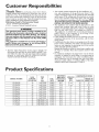 6
6
-
 7
7
-
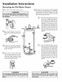 8
8
-
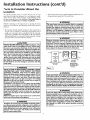 9
9
-
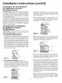 10
10
-
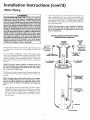 11
11
-
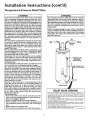 12
12
-
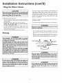 13
13
-
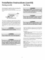 14
14
-
 15
15
-
 16
16
-
 17
17
-
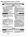 18
18
-
 19
19
-
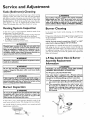 20
20
-
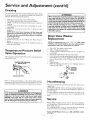 21
21
-
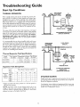 22
22
-
 23
23
-
 24
24
-
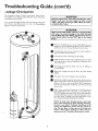 25
25
-
 26
26
-
 27
27
-
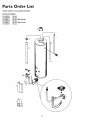 28
28
-
 29
29
-
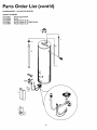 30
30
-
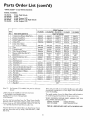 31
31
-
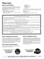 32
32


Kenmore 153336150 User manual
- Category
- Water heaters & boilers
- Type
- User manual
Ask a question and I''ll find the answer in the document
Finding information in a document is now easier with AI
Related papers
-
Kenmore 153.337072 User manual
-
Sears 153.336701 User manual
-
-
-
-
-
-
-
-
Other documents
-
Rheem XG50T06TN34UO User guide
-
-
Apollo Hydroheat A650YRRTL5 User manual
-
Rheem XG50T09EN38U0 User manual
-
Reliance Water Heaters FVIR GAS WATER HEATER User manual
-
State Water Heaters ES6-20-SOMS-K User manual
-
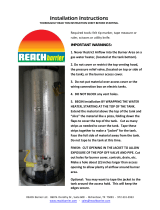 Reach Barrier 3016 Installation guide
-
State Water Heaters P6-30-2OT1 User manual
-
HTP Everlast Light Duty Commercial Electric Water Heater Installation Drawings
-
