Back to Contents Page
System Setup
Dell™Vostro™V13ServiceManual
Overview
Entering System Setup
System Setup Screens
System Setup Options
Overview
Use System Setup as follows:
l To change the system configuration information after you add, change, or remove any hardware in your computer
l To set or change a user-selectable option such as the user password
l To read the current amount of memory or set the type of hard drive installed
Before you use System Setup, it is recommended that you write down the System Setup screen information for future reference.
Entering System Setup
1. Turn on (or restart) your computer.
2. WhentheblueDELL™logoisdisplayed,youmustwatchfortheF2prompttoappear.
3. Once this F2 prompt appears, press <F2> immediately.
4. If you wait too long and the operating system logo appears, continue to wait until you see the Microsoft
®
Windows
®
desktop. Then, shut down your
computer and try again.
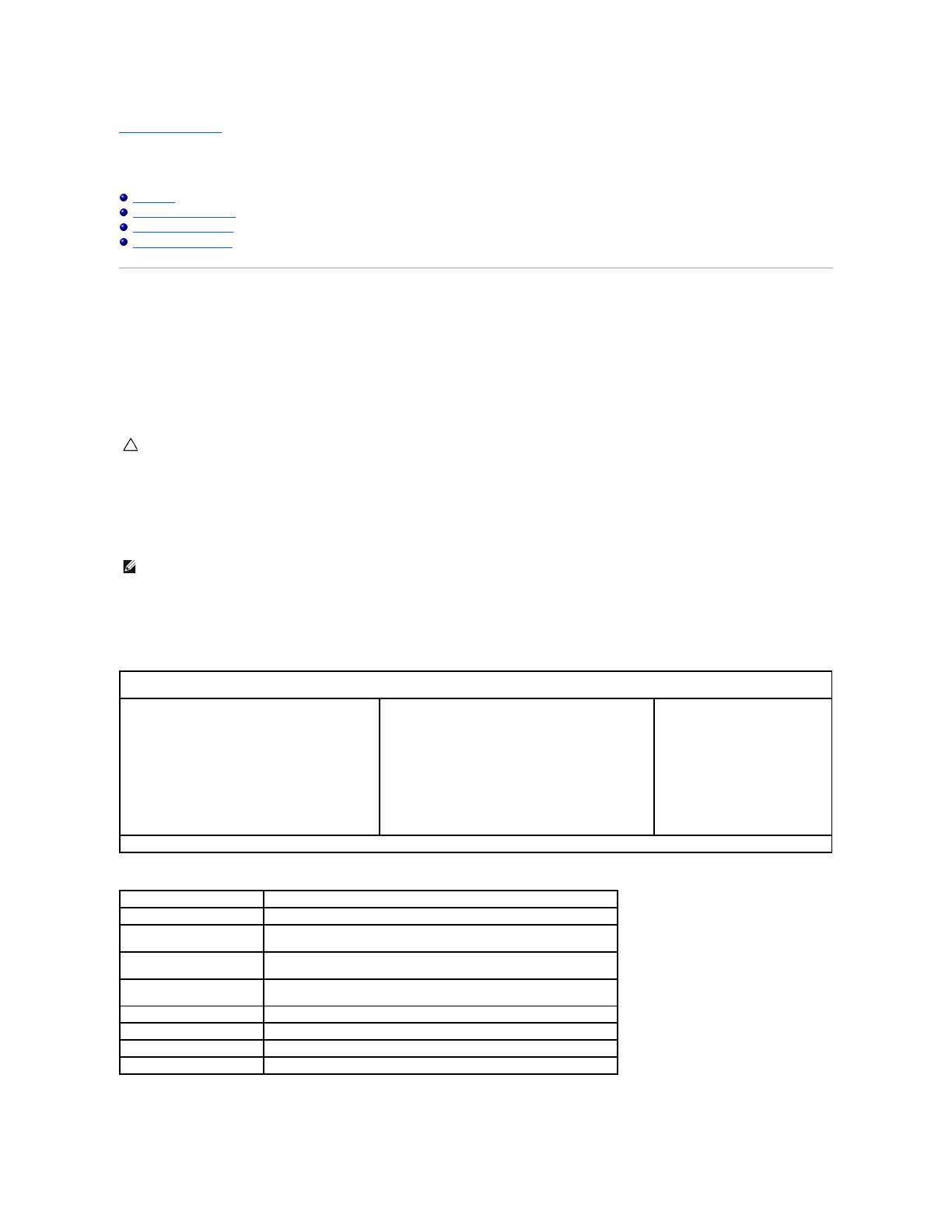
System Setup Screens
Use the following keys to navigate through System Setup screens:
CAUTION: Unless you are an expert computer user, do not change the settings for this program. Certain changes can make your computer work
incorrectly.
NOTE: The F2 prompt indicates that the keyboard has initialized. This prompt can appear very quickly, so you must watch for it to display, and then
press <F2>. If you press <F2> before you are prompted, this keystroke will be lost.
Menu — Appears on top of the System Setup window. This field provides a menu to access to the System Setup options. Press <\xdf >and< >keys to
navigate. As a Menu option is highlighted, the Options List, lists the options that define the hardware installed on you computer.
Options List — Appears on the left side of the System
Setup window. The field lists features that define the
configuration of your computer, including installed
hardware, power conservation, and security features.
Scroll up and down the list with the up- and down-
arrow keys. As an option is highlighted, the Options
Field displays the option's current and available
settings.
Options Field — Appears on the right side of Options List
and contains information about each option listed in the
Options List. In this field you can view information about
your computer and make changes to your current settings.
Press <Enter> to make changes to your current settings.
Press <ESC> to return to the Options List.
NOTE: Not all settings listed in the Options Field are
changeable.
Help — Appears on the right side of
the System Setup window and
contains help information about the
option selected in Options List.
Key Functions — Appears below the Options Field and lists keys and their functions within the active system setup field.
Displays information on any selected item in the System Setup.
Exit from current view or switch the current view to the Exit page in the
System Setup.
< Up Arrow > or < Down
Arrow >
Select an item to display.
< Left Arrow > or < Right
Arrow >
Select a menu to display.
Change existing item value.
Select the sub menu or execute command.
Save current configuration and exit System Setup.


