Page is loading ...

SOUNDCRAFT CPS2000
Console Power Supply
User and Technical Manual
IMPORTANT: please read this manual carefully before
connecting your Soundcraft console power supply to
the mains for the first time.
For your own safety and to avoid invalidation of the
warranty all text marked with these Warning Symbols
should be read carefully.

© Harman International Industries Ltd. 1997, 2005
All rights reserved
Parts of the design of this product may be protected by world-wide patents.
Part No. ZM0198-05
Soundcraft is a trading division of Harman International Industries Ltd.
Information in this manual is subject to change without notice and does not
represent a commitment on the part of the vendor. Soundcraft shall not be liable for
any loss or damage whatsoever arising from the use of information or any error
contained in this manual, or through any mis-operation or fault in hardware
contained in the product.
No part of this manual may be reproduced, stored in a retrieval system, or
transmitted, in any form or by any means, electronic, electrical, mechanical, optical,
chemical, including photocopying and recording, for any purpose without the
express written permission of Soundcraft.
It is recommended that all maintenance and service on the product should be
carried out by Soundcraft or its authorised agents. Soundcraft cannot accept any
liability whatsoever for any loss or damage caused by service, maintenance or
repair by unauthorised personnel.
Harman International Industries Ltd.
Cranborne House
Cranborne Road
Potters Bar
Herts.
EN6 3JN
England
Tel: 01707 665000
Fax: 01707 660482
www.soundcraft.com

Contents
Introduction 1
Mains Voltage Selection 2
Operating Voltage Range 4
Replacing Mains Fuse 4
Warranty 5
Recommendations for Installation 7
PSU Linking 10
Dimensions 11
Technical Specification 13
Circuit Description 15
Parts List 25
Fan Control 35
Technical Drawings 39
i

ii

Introduction
Introduction 1

IMPORTANT SAFETY INSTRUCTIONS
· Read these instructions.
· Keep these instructions.
· Heed all warnings.
· Follow all instructions.
· Do not use this apparatus near water.
· Clean only with a dry cloth.
· Do not block any ventilation openings. Ventilation should not be impeded by covering the ventilation
openings with items such as newspapers, table cloths, curtains etc. Install in accordance with the
manufacturer’s instructions.
· Do not install near any heat sources such as radiators, heat registers, stoves, or other apparatus (including
amplifiers) that produce heat.
· Do not defeat the safety purpose of a polarised or grounding type plug. A polarised plug has two blades with
one wider than the other. A grounding type plug has two blades and a third grounding prong. The wide
blade or the third prong are provided for your safety. If the provided plug does not fit into your outlet, consult
an electrician for replacement of the obsolete outlet
· Protect the power cord from being walked on or pinched particularly at plugs, convenience receptacles and
the point where they exit from the apparatus.
· Only use attachments/accessories specified by the manufacturer.
· Use only with the cart, stand, tripod, bracket or table specified by the manufacturer, or sold with the apparatus.
When a cart is used, use caution when moving the cart/apparatus combination to avoid injury from tip-over.
· Unplug this apparatus during lightning storms or when unused for long periods of time.
· Refer all servicing to qualified service personnel. It is recommended that all maintenance and service on the
product should be carried out by Soundcraft or its authorised agents. Soundcraft cannot accept any liability
whatsoever for any loss or damage caused by service, maintenance or repair by unauthorised personnel.
Servicing is required when the apparatus has been damaged in any way, such as power-supply cord or plug
is damaged, liquid has been spilled or objects fallen into the apparatus, the apparatus has been exposed to
rain or moisture, does not operate normally, or has been dropped.
· No naked flame sources, such as lighted candles, should be placed on the apparatus.
· WARNING: To reduce the risk of fire or electric shock, do not expose this apparatus to rain or moisture.
Do not expose the apparatus to dripping or splashing and do not place objects filled with liquids, such as
vases, on the apparatus.
· Terminals marked with the lightning symbol are hazardous live and the external wiring connected to these
terminals requires installation by an "instructed person" or the use of ready made leads or cords.
· THIS APPARATUS MUST BE EARTHED. Under no circumstances should the safety earth be
disconnected from the mains lead.
· The mains supply disconnect device is the mains plug. It must remain accessible so as to be readily operable
when the apparatus is in use.
· If any part of the mains cord set is damaged, the complete cord set should be replaced. The following
information is for reference only.
· The wires in the mains lead are coloured in accordance with the following code:
· Earth (Ground):Green and Yellow (US - Green/Yellow)
· Neutral:Blue (US - White)
· Live (Hot):Brown (US - Black)
· As the colours of the wires in the mains lead may not correspond with the coloured markings identifying the
terminals in your plug, proceed as follows:
· The wire which is coloured Green and Yellow must be connected to the terminal in the plug which is marked
with the letter E or by the earth symbol
· The wire which is coloured Blue must be connected to the terminal in the plug which is marked with the
letter N
· The wire which is coloured Brown must be connected to the terminal in the plug which is marked with the
letter L
· Ensure that these colour codes are followed carefully in the event of the plug being changed
· This unit is capable of operating over a range of mains voltages as marked on the rear panel. It is important
to ensure that the correct mains fuse is fitted before switching on the unit.
2 Introduction

Introduction
WARNING: THIS APPARATUS MUST BE EARTHED
The CPS2000 is a linear power supply which, like other linear supplies, produces DC
voltages by rectifying, smoothing and regulating AC voltages from the secondary
windings of a mains transformer. Soundcraft mixing consoles employ a number of
dc voltage supply levels in their operation and these are all provided at the output of
each supply unit.
In regulating these voltages there is considerable heat generated, the dissipation of
which is achieved through a substantial heat sink on each side of the unit. Two fans
are incorporated which draw air over the heatsinks to provide adequate heat dissipation
for the regulators and reduce the outer case temperature.
The CPS2000 is designed for installation in a 19" rack unit, occupying 4U of rack
height. Refer to the section "RECOMMENDATIONS FOR INSTALLATION" on
Page 7.
LEDs are provided on the front panel to show the operation of the regulating circuits,
and a digital voltmeter monitors the mains supply voltage.
The CPS2000 may be linked to a second CPS2000 to provide automatic power backup
in the event of one of the units failing.
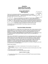
MAINS VOLTAGE SELECTION.
Special attention should be paid to the following information:
Do not change the voltage setting without first turning
the unit off and unplugging the mains lead. Ensure that
the cover plate over the mains voltage selection
switches is replaced after correct voltage selection
has been made and that the cover plate is positioned
to show the correct mains voltage.
This unit is capable of operating over a wide range of mains voltages by means of a
comprehensive set of selectable voltage settings. It is important to ensure that the
correct voltage setting has been selected for the level of local mains voltage supply,
for safe, uninterrupted operation of the unit.
There are two mains voltage selection switches behind a cover plate on the front of
the unit. Voltage selection is achieved by moving the switches using a screwdriver
blade, into the correct positions, as shown by the symbols marked on the front panel.
In this way the unit is set up for operation at one of the following ranges of mains
supply:
NOMINAL VOLTAGE OPERATING VOLTAGE RANGE
Vrms AC Vrms AC
230 195-253
200 170-220
115 98-126
100 85-110
Introduction 3

200V
230V
100V
115V
Mains Voltage Selector Positions
CAUTION
RISK OF ELECTRIC SHOCK
DO NOT OPEN
RISK OF ELECTRIC SHOCK
DO NOT OPEN
AVIS: RISQUE DE CHOC ELECTRIQUE
- NE PAS OUVRIR
AVIS: RISQUE DE CHOC ELECTRIQUE
- NE PAS OUVRIR
NO USER SERVICEABLE PARTS INSIDE
NO USER SERVICEABLE PARTS INSIDE
NO USER SERVICEABLE PARTS INSIDE
NO USER SERVICEABLE PARTS INSIDE
PIN 1, 2, 3, 4 +17V 16A
PIN 1, 2, 3, 4 +17V 16A
9, 10, 11, 12 -17V 16A
9, 10, 11, 12 -17V 16A
13 +48V
13 +48V
18 +8V
18 +8V
19
NOT USED
NOT USED
1.25A
5, 6, 7, 8 +0V
5, 6, 7, 8 +0V
16, 17 0V
16, 17 0V
0.5A
14, 15 CHASSIS GROUND
14, 15 CHASSIS GROUND
( BOTH DC CONNECTORS HAVE
IDENTICAL PINOUT )
( BOTH DC CONNECTORS HAVE
IDENTICAL
PINOUT )
DC POWER OUT
TO CONSOLE
DC POWER OUT
TO CONSOLE
DC POWER IN
FROM STANDBY SUPPLY
DC POWER IN
FROM STANDBY SUPPLY
TO REDUCE THE RISK
OF FIRE OR ELECTRIC SHOCK
OF FIRE OR ELECTRIC SHOCK
DO NOT EXPOSE THIS UNIT
DO NOT EXPOSE THIS UNIT
TO RAIN OR MOISTURE
DO NOT COVER ANY VENTILATION
DO NOT COVER ANY VENTILATION
SLOTS AS THIS MAY CAUSE THE
SLOTS AS THIS MAY CAUSE THE
EQUIPMENT TO OVERHEAT
EQUIPMENT TO OVERHEAT
WARNING:
MAINS VOLTAGE SELECTION
200V
100V
115V
230V
200V
230V
100V
115V
48V
+
8V
HIGH TEMP
+
17V
CLEAN FAN FILTERS REGULARLY
DO NOT COVER
ANY VENTILATION SLOTS, AS
THIS MAY CAUSE THE EQUIPMENT
TO OVERHEAT
WARNING:
+
17V
-
ACCESS TO MAINS VOLTAGE SELECTION SWITCHES
WARNING: DISPLAY MAINS VOLTAGE SETTING IN
SIDE WINDOW WHEN REFITTING COVER PLATE.
UNDER COVER PLATE.
ENSURE CORRECT MAINS VOLTAGE
SETTING AND CORRECT FUSE BEFORE
CONNECTING MAINS SUPPLY.
DO NOT SWITCH MAINS VOLTAGE SETTINGS
WHILE MAINS SUPPLY IS CONNECTED.
DOTS LIGHT WHEN MAINS LOW
POWER
ON
1
0
OFF
MAINS VOLTAGE
CONSOLE POWER SUPPLY
CPS
2
000
MAINS FUSE:
CAUTION:
ATTENTION:
100V/230V USE T10.0A/250V
TO REDUCE THE RISK OF
AFIN DE REDUIRE LE
RISQUE DE FEU, REMPLACER SEULEMENT
AVEC FUSIBLE DE MEME TYPE.
FIRE, REPLACE WITH SAME
TYPE FUSE ONLY.
Front and Rear Panel Views
4 Introduction

OPERATING VOLTAGE RANGE
It is very important to use the correct mains voltage selection. A wide operating range
of mains voltages is provided to enable the unit to function down to only 85Vrms on
the mains supply. This facility is incorporated to overcome the problems that some
power supplies have with internal regulation when operating from a poorly regulated
mains supply.
Do not operate the PSU with a consistently high (above
nominal) reading on the mains meter. Operation with
the mains higher than +10% may cause serious
damage
The mains meter is essentially a peak-reading device, as it is the peak value of the
mains waveform which is the most important factor in providing the correct mains
voltage to the power supply. For this reason, and because with long power cables it
is common for the mains waveform to become distorted, the indication of the meter
may not agree with readings taken with the usual types of quasi-RMS reading
testmeter.
Note that the meter measures the voltage actually available at the PSU, and therefore
will indicate any voltage drop on mains supply wiring.
REPLACING MAINS FUSE.
In the event of incorrect switching of the mains voltage selectors, a mains power surge
or underrated fuse value, the mains fuse in the front panel will blow and the CPS2000
will not function. Switch the ON/OFF switch to the OFF position. Check the fuse
and replace if necessary; also check that the voltage selection is correct for the mains
supply level before switching the unit ON again.
To avoid risk of fire replace only with the correct value
fuse, as indicated on the unit.
In the event of repeated failure of the mains fuse consult the Soundcraft dealer from
where the unit was purchased.
This unit contains no user serviceable parts. Refer all
servicing to a qualified service engineer, through the
appropriate Soundcraft dealer.
Introduction 5

1 Soundcraft is a trading division of Harman International Industries Ltd.
End User means the person who first puts the equipment into regular operation.
Dealer means the person other than Soundcraft (if any) from whom the End User
purchased the Equipment, provided such a person is authorised for this purpose by
Soundcraft or its accredited Distributor.
Equipment means the equipment supplied with this manual.
2 If within the period of three years from the date of delivery of the Equipment to the
End User it shall prove defective by reason only of faulty materials and/or
workmanship to such an extent that the effectiveness and/or usability thereof is
materially affected the Equipment or the defective component should be returned to
the Dealer or to Soundcraft and subject to the following conditions the Dealer or
Soundcraft will repair or replace the defective components. Any components
replaced will become the property of Soundcraft.
3 Any Equipment or component returned will be at the risk of the End User whilst in
transit (both to and from the Dealer or Soundcraft) and postage must be prepaid.
4 This warranty shall only be available if:
a) the Equipment has been properly installed in accordance with instructions
contained in Soundcraft’s manual; and
b) the End User has notified Soundcraft or the Dealer within 14 days of the defect
appearing; and
c) no persons other than authorised representatives of Soundcraft or the Dealer have
effected any replacement of parts maintenance adjustments or repairs to the
Equipment; and
d) the End User has used the Equipment only for such purposes as Soundcraft
recommends, with only such operating supplies as meet Soundcraft’s specifications
and otherwise in all respects in accordance Soundcraft’s recommendations.
5 Defects arising as a result of the following are not covered by this Warranty: faulty
or negligent handling, chemical or electro-chemical or electrical influences,
accidental damage, Acts of God, neglect, deficiency in electrical power,
air-conditioning or humidity control.
6. The benefit of this Warranty may not be assigned by the End User.
7. End Users who are consumers should note their rights under this Warranty are in
addition to and do not affect any other rights to which they may be entitled against
the seller of the Equipment.
Warranty
6 Introduction

Recommendations for
Installation of the CPS 2000
Installation 7

Recommendations for Installation
The CPS2000 power supply is provided with front panel fixing holes for 19"
rack-mounting and will occupy 4U of rack space. Rear support should be provided
when fitted in a 19" rack.
The CPS2000 is a heavy unit (30kg,) and should be
regarded as a two-man lift. Take suitable precautions
when lifting
As with any power supply that contains a large mains-voltage transformer, it is
preferable to provide a degree of physical isolation of the unit from other electronic
equipment, particularly that which carries low level audio signals, to avoid any
possible hum pick-up. For this reason the unit is used with a long (6.5 metres) output
cable to enable it to be positioned away from the mixing console.
For the same reason, when rack-mounting it is preferable to avoid locating the unit
adjacent to signal processing equipment.
It should be noted that if a complete rack containing a CPS2000 unit is to be operated
from a different mains supply level, then the unit should be withdrawn from the rack
in order to reselect the mains voltage setting, at the same time as resetting any other
equipment.
The other important consideration when rack-mounting the unit is the need for natural
convection of air over the case and an unrestricted air flow through the unit. Note that
air is drawn in at the front of the unit and expelled through the rear panel.
Good ventilation BELOW the unit, in the floor or back of the rack, and similarly
ABOVE the unit, at the top of the rack, will ensure a path for continuous air flow.
Other equipment in the rack which is known NOT to produce a significant amount of
heat should be mounted BELOW the unit. Equipment that also relies on good air flow
within the rack (ie. most power amplifiers and other power supplies) should be given
due consideration and some space should be provided between such units and between
these and the CPS2000 unit. Forced convection, by means of a fan-tray, may be
desirable in this situation.
The CPS2000 will operate as a free-standing unit
without requiring any special cooling arrangement,
but should not be allowed to be accidentally or
deliberately covered over in any way.
Do not operate the unit with the top cover removed as
this exposes hazardous voltages.
The filters on the cooling fans must be inspected
regularly and cleaned if necessary to maintain good
airflow through the unit. This will be particularly
important if the unit is used in a dusty environment.
8 Installation

Finally, some consideration should be given to the earthing arrangement of the system
at the centre of which are the console and the CPS2000 (and any other Soundcraft
power supply units). The console chassis is earthed, through the mains earth, via the
power supply. When rack-mounting the CPS2000(and any other Soundcraft power
supply units) care should be taken to avoid any possible ‘ground loops’ in the system
which would introduce audible hum to otherwise clean audio signals. Ground loops
may occur where signal processing equipment, patched to the console, has its signal
earth commoned to the equipment chassis. The ground loop is formed if this chassis
and the power supply chassis are in electrical contact through the fixing rails they
share in the rack. To avoid this situation, standard isolating washers may be employed
when fixing the power supply (or supplies) or any other unit into the rack.
W A R N I N G : THIS APPARATUS MUST BE
EARTHED. Under no circumstances should the mains
earth be disconnected from the CPS2000 power supply
unit.
GENERAL
As with all electrical/electronic equipment care should be taken when handling this
unit. Avoid general mishandling and do not drop. Avoid storage and operation in
dusty locations and do not expose to corrosive atmospheres.
To avoid risk of fire do not expose this unit to rain or
moisture.
Retain all packaging for transportation in the event of the unit requiring servicing.
Retain this manual safely, along with all other relevant documents.
For touring/mobile transportation it is advisable to install the CPS2000 in a flight case
to provide mechanical protection. Refer to your Soundcraft dealer for a suitable case.
Where the CPS2000 is enclosed in a touring case, provision must be made for adequate
ventilation to the rear of the unit to ensure unrestricted supply of air for the cooling
fan.
Use only the 16 Amp mains lead supplied, no other
type is to be used.
Use only the DC output lead supplied, no other type is
to be used.
Installation 9

PSU Linking
Link the second PSU to the first as shown in the following diagram.
Note that the linking cable is included when a spare CPS2000 is ordered.
CAUTION
RISK OF ELECTRIC SHOCK
DO NOT OPEN
RISK OF ELECTRIC SHOCK
DO NOT OPEN
AVIS: RISQUE DE CHOC ELECTRIQUE
- NE PAS OUVRIR
AVIS: RISQUE DE CHOC ELECTRIQUE
- NE PAS OUVRIR
NO USER SERVICEABLE PARTS INSIDE
NO USER SERVICEABLE PARTS INSIDE
NO USER SERVICEABLE PARTS INSIDE
NO USER SERVICEABLE PARTS INSIDE
PIN 1, 2, 3, 4 +17V 16A
PIN 1, 2, 3, 4 +17V 16A
9, 10, 11, 12 -17V 16A
9, 10, 11, 12 -17V 16A
13 +48V
13 +48V
18 +8V
18 +8V
19
NOT USED
NOT USED
1.25A
5, 6, 7, 8 +0V
5, 6, 7, 8 +0V
16, 17 0V
16, 17 0V
0.5A
14, 15 CHASSIS GROUND
14, 15 CHASSIS GROUND
( BOTH DC CONNECTORS HAVE
IDENTICAL PINOUT )
( BOTH DC CONNECTORS HAVE
IDENTICAL
PINOUT )
DC POWER OUT
TO CONSOLE
DC POWER OUT
TO CONSOLE
DC POWER IN
FROM STANDBY SUPPLY
DC POWER IN
FROM STANDBY SUPPLY
TO REDUCE THE RISK
OF FIRE OR ELECTRIC SHOCK
OF FIRE OR ELECTRIC SHOCK
DO NOT EXPOSE THIS UNIT
TO RAIN OR MOISTURE
TO RAIN OR MOISTURE
DO NOT COVER ANY VENTILATION
DO NOT COVER ANY VENTILATION
SLOTS AS THIS MAY CAUSE THE
SLOTS AS THIS MAY CAUSE THE
EQUIPMENT TO OVERHEAT
EQUIPMENT TO OVERHEAT
WARNING:
To Console
10 Installation

Dimensions
All dimensions in millimeters
Installation 11

12 Installation

Technical Specification
Technical Specification 13

Technical Specification
MAINS INPUT VOLTAGE RANGE:
230/200/115/100 V AC +10% / -15% @ 50/60Hz
RATED INPUT POWER (Max):
980 WATTS
MAINS FUSE RATING:
Use T10AL/250V (slow-blow).
OUTPUTS
DC. VOLTAGE RAIL MAX. OUTPUT CURRENT
+17V 16.00 AMPS
-17V 16.00 AMPS
+48V 0.30 AMPS
+8V 1.25 AMPS
All voltage and current measurements are to be taken
at the console-end of the power supply cable.
OPERATING TEMPERATURE RANGE (Ambient):
-10 TO +40°C.
HUMIDITY:
Similar unit tested at 0-90% RH non-condensing +/-5% Relative Humidity
at 40 °C for 16 hours. Load switched between 20% and 100% at regular
30 minute intervals.
OVERALL DIMENSIONS:
HEIGHT: 177.00mm. (4U)
WIDTH: Chassis 440.00mm.
Front panel 482.60mm.
DEPTH: (excl. handles) 436.00mm.
WEIGHT:
(Excl. packing): 30Kg
14 Technical Specification

Circuit Description
CAUTION:THE FOLLOWING SECTIONS ARE FOR USE
BY QUALIFIED SERVICE PERSONNEL ONLY. TO
REDUCE THE RISK OF ELECTRIC SHOCK, DO NOT
PERFORM ANY SERVICING, OTHER THAN THAT
CONTAINED IN PREVIOUS SECTIONS, UNLESS YOU
ARE QUALIFIED TO DO SO.
Circuit Description 15

Circuit Description
INTRODUCTION.
The CPS2000 power supply provides +/-17V at 16 Amps, +8V at 1.25 Amp, and +48V
at 0.3 Amp. The main PCB (SC3804) is in LH and RH halves. The LH PCB carries
the +17V and +48V supplies. The RH PCB carries the -17V and +8V supplies. A
separate PCB (SC3817) carries the mains voltage selector switches at the front of the
unit.
THE +/- 17V RAILS. SC3804
This consists of two identical +17V supplies connected together to give +/-17V.
Each 17V supply is a linear regulator with conventional fullwave rectification and a
large (100,000uF) reservoir capacitor. This is combined with a second power supply
that powers the driver transistors, the cooling fan, and the digital mains meter. The
main series pass elements are 250W discrete bipolar transistors connected in parallel
with suitable current-sharing precautions and mounted on a fan-cooled heatsink. The
voltage reference and servo control amplifier is provided by a 723 regulator IC. The
circuitry of the +17V regulator is described in detail below:
The +17V Supply. (LH PCB)
The transformer secondary is fused by means of 32 Amp Safeclip (BS88) fuses
mounted in holders on the floor of the chassis. They are NOT intended for customer
replacement. A spare fuse will be provided, but it is stressed that these fuses will only
blow in the event of catastrophic failure, such as a major short in the wiring or a failed
bridge rectifier.
The fullwave bridge rectifier is mounted on the heatsink, at the hottest end as it is the
most heat-tolerant of the semiconductors. The reservoir capacitors are mounted by
clips on the floor of the chassis. For safety reasons, the reservoir capacitor is
discharged by bleeder resistor R9 at switchoff; this takes about 30 seconds. A red
warning LED on the PCB is on whenever the capacitor is charged. The unregulated
DC is approx +26 to +29V.
The 723 IC contains a 7.15V nominal Zener diode, defining the voltage that appears
at Pin 6. Zener references generate appreciable noise, and this, plus any ripple, is
filtered out by R10,C10. R10 is in series with the positive input of the servo opamp
(Pin 5) and is made roughly equal in resistance to the feedback divider R16,17 etc to
minimise bias-current offsets.
The feedback divider R16,17,18 & PR1 derives a fraction of the output voltage and
delivers it to the negative input of the servo opamp. (Pin 4) The negative feedback
keeps this point also at 17.15V, so the actual output voltage is determined by the
feedback divider ratio, which is trimmed over a narrow range by PR3.
The output of the servo opamp controls the output through TR8, which is an emitter
follower driving the parallel pass devices TR4,5,6. R41 is included for diagnostic
purposes, so that the current being supplied by the 723 (only a few mA) can be
measured. The power supply to TR8 is taken from the +12V supply. This has its 0V
side connected to the positive unregulated DC supply of 26 - 29V, (at nominal mains)
giving a total voltage of approx 38 - 41V for the driver; this also powers the 723 IC.
This subrail markedly reduces the minimum drop across the pass elements and
therefore increases the efficiency.
16 Circuit Description
/