Page is loading ...

FP596A
1/14/99
Homeowner’s Installation and
Operating Manual
Builder Direct Vent
DO NOT STORE OR USE
GASOLINE OR OTHER
FLAMMABLE VAPORS AND
LIQUIDS IN THE VICINITY OF THIS
OR ANY OTHER APPLIANCE.
WHAT TO DO IF YOU SMELL GAS:
• Do not try to light any appliance.
• Do not touch any electric switch; do
not use any phone in your building.
• Immediately call your gas supplier
from your neighbor’s phone. Follow
the gas suppliers instructions.
• If you cannot reach your gas supplier
call the fire department.
WARNING!
IF THE INFORMATION IN THIS
MANUAL IS NOT FOLLOWED
EXACTLY, A FIRE OR EXPLOSION
MAY RESULT CAUSING PROPERTY
DAMAGE, PERSONAL INJURY OR
LOSS OF LIFE.
PLEASE READ THIS MANUAL
BEFORE INSTALLING AND USING
APPLIANCE
INSTALLER/CONSUMER
SAFETY INFORMATION
Models: DVBR36
DVBR42
CE RT IFI ED
D
E
S
I
G
N
C
E
R
T
I
F
I
E
D
20000584 1/07 Rev. 16
FOR YOUR SAFETY
Installation and service must be
performed by a qualified installer,
service agency or the gas supplier.
INSTALLER: Leave this manual with the appliance.
CONSUMER: Retain this manual for future reference.

2
DVBR Series Direct Vent Gas Fireplace
20000584
Installation & Operating Instructions
General Information ....................................................................................................................3
Fireplace Dimensions .................................................................................................................
4
Locating Your Fireplace ..............................................................................................................
6
Clearance to Combustibles .........................................................................................................
6
Mantels ......................................................................................................................................
6
Mantel Chart ...............................................................................................................................6
Hearth ......................................................................................................................................
7
Framing and Finishing ................................................................................................................
7
Final Finishing .............................................................................................................................
7
Gas Specifications ......................................................................................................................
7
Gas Inlet & Manifold Pressures ..................................................................................................7
High Elevations ...........................................................................................................................
7
Gas Line Installation ...................................................................................................................
7
Remote Switch Installation ..........................................................................................................
8
EB-1 Electrical Box .....................................................................................................................
8
Optional Top Vent Application .....................................................................................................8
General Venting Information
General Venting ........................................................................................................................10
General Venting Information - Termination Location ................................................................. 11
General Information Assembling Vent Pipes .............................................................................12
How to Use the Vent Graph ......................................................................................................13
Rear Wall Vent Applications & Installation ................................................................................
13
Vertical Sidwall Applications & Installation ................................................................................
15
Below Grade Installation ...........................................................................................................
19
DVBR36 Vertical Installation Baffle Adjustment ........................................................................
19
Vertical Through-the-Roof Applications & Installation ...............................................................20
Venting Components .................................................................................................................
22
Operating Instructions
Glass Information ......................................................................................................................
23
Glass Frame Removal ..............................................................................................................
23
Glass Cleaning ..........................................................................................................................23
Replacement of Ceramic Hearth Panels ...................................................................................
23
Installation of Logs ....................................................................................................................
24
Ember Material Placement ........................................................................................................
24
Lava Rock .................................................................................................................................
24
Flame & Temperature Adjustment .............................................................................................25
Flame Characteristics ...............................................................................................................
25
Inspecting the Venting System ..................................................................................................
25
Lighting & Operating Instructions ..............................................................................................
27
Troubleshooting ........................................................................................................................
29
Fuel Conversion Instructions ....................................................................................................30
Maintenance
Cleaning the Standing Pilot Control System .............................................................................
32
Replacement Parts ..............................................................................................................................33
Optional Accessories
FK-12 Fan Kit ............................................................................................................................
35
Remote Controls .......................................................................................................................
35
Ceramic Refractory Panels .......................................................................................................
35
Decorative Glass Panels ...........................................................................................................
36
Decorative Frame Trims ............................................................................................................
36
Warranty ...............................................................................................................................................39
Please Read the Installation & Operating Instructions Before Using Appliance.
Thank you and congratulations on the purchase of a CFM Corporation fireplace.
IMPORTANT: Read all instructions and warnings carefully before starting installation. Failure to follow these
instructions may result in a possible fire hazard and will void the warranty.
Table of Contents

3
DVBR Series Direct Vent Gas Fireplace
20000584
Installation Instructions
This gas appliance should be installed by a qualified installer in
accordance with local building codes and with current CSA-
B149.1 Installation codes for Gas Burning Appliances and
Equipment. If the unit is being installed in a mobile home, the
installation should comply with the current CAN/CSA Z 240.4
code. For U.S.A Installations follow local codes and/or the
current National Fuel Gas Code. ANSI Z223.1/NFPA 54.
In the Commonwealth of Massachusetts, all gas fitting
and installation of this heater shall only be done by a
licensed gas fitter or licensed plumber.
FOR SAFE INSTALLATION AND OPERATION PLEASE
NOTE THE FOLLOWING:
1. This fireplace gives off high temperatures and should be
located out of high traffic areas and away from furniture
and draperies.
2. Children and adults should be alerted to the hazards of the
high surface temperatures of this fireplace and should stay
away to avoid burns or ignition of clothing.
3. Children should be carefully supervised when in the same
room as your fireplace.
4. Under no circumstances should this fireplace be modified.
Parts removed for servicing should be replaced prior to
operating this fireplace again.
5. Installation and any repairs to this fireplace must be
performed by a qualified installer, service agency or gas
supplier. A professional service person should be contacted
to inspect this fireplace annually. Make it a practice to have
all of your gas fireplaces checked annually. More frequent
cleaning may be required due to excess lint and dust from
carpeting, bedding material, etc.
6. Control compartments, burners and air passages in this
fireplace should be kept clean and free of dust and lint.
Make sure the gas valve and pilot light are turned off be-
fore you attempt to clean this fireplace.
7. The venting system (chimney) of this fireplace should be
checked at least once a year and if needed your venting
system should be cleaned.
8. Keep the area around your fireplace clear of combustible
materials, gasoline and other flammable vapor and liquids.
This fireplace should not be used as a drying rack for cloth
-
ing, nor should Christmas stocking or decorations be hung
in the area of it.
9. Under no circumstances should any solid fuels (wood,
coal, paper or cardboard etc.) be used in this fireplace.
10. The flow of combustion and ventilation air must not be
obstructed in any way.
11. When fireplace is installed directly on carpeting, vinyl tile or
any combustible material other than wood, this fireplace
must be installed on a metal or wood panel extending the
full width and depth of the fireplace.
12. This fireplace requires adequate ventilation and combustion
air to operate properly.
13. This fireplace must not be connected to a chimney flue
serving a separate solid fuel burning fireplace.
14. When the fireplace is not in use it is recommended that the
gas valve be left in the OFF position.
IMPORTANT:
PLEASE READ THE FOLLOWING CAREFULLY
Remove any plastic from trim parts before turning the
fireplace ON.
It is normal for fireplaces fabricated of steel to give off
some expansion and/or contraction noises during the
start up or cool down cycle. Similar noises are found
with your furnace heat exchanger or car engine. It is
not unusual for your gas fireplace to give off some odor
the first time it is burned. This is due to the manufactur-
ing process.
Please ensure that your room is well ventilated
-open all windows.
It is recommended that you burn your fireplace for at
least ten (10) hours the first time you use it. If the op
-
tional fan kit has been installed, place the fan switch in
the “OFF” position during this time.
Proposition 65 Warning: Fuels used in gas, wood-
burning or oil fired appliances, and the products of
combustion of such fuels, contain chemicals known to
the State of California to cause cancer, birth defects
and other reproductive harm.
California Health & Safety Code Sec. 25249.6
This appliance may be installed in an aftermarket
permanently located, manufactured home or mobile home,
where not prohibited by local codes.
This appliance is only for use with the type of gas indicated
on the rating plate. This appliance is not convertible for
use with other gases, unless a certified kit is used.
The DVBR has been approved for mobile home
installations.
WARNING: Check with your electronics manufacturer
before installing a television or other electronic de-
vice above this fireplace.

4
DVBR Series Direct Vent Gas Fireplace
20000584
584
Specs - top vent
2/14/02 djt
P - Rough Opening Width
Rough
Opening
Height
Rough
Opening
Depth
S
S
T
5/8” (16 mm)
R
Q
G
H
I
M
N
5/8” (16 mm)
E
D
F
O
B
A
C
K
L
Gas Line
Access
"
Electrical
Access
C
L
J
K
"
"
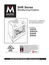
Fireplace Dimensions (Installed as Top Vent)
Fig. 2 Fireplace specifications and framing dimensions.
Ref. DVBR36 DVBR42
A 40” (1016 mm) 46” (1168 mm)
B 36” (614 mm) 36” (914 mm)
C 36” (914 mm) 42” (1067 mm)
D 23¹⁄₄” (591 mm) 24¹⁄₄” (616 mm)
E 6³⁄₈” (162 mm) 6³⁄₈” (162 mm)
F 6³⁄₈” (162 mm) 5³⁄₈” (137 mm)
G 20” (508 mm) 20” (508 mm)
H 6
³⁄₄” (172 mm) 6³⁄₄” (172 mm)
I 22” (559 mm) 28” (711 mm)
J 13¹⁄₄” (337 mm) 13¹⁄₄” (337 mm)
K 3” (76 mm) 3” (76 mm)
L 6¹⁄₂” (165 mm) 6¹⁄₂” (165 mm)
M 4” (102 mm) Dia. 4” (102 mm) Dia.
N 7” (178 mm) Dial. 7” (178 mm) Dia.
Framing Dimensions
O 40¹⁄₂” (1029 mm) 40¹⁄₂” (1029 mm)
P 41” (1041 mm) 47” (1194 mm)
Q 20¹⁄₂” (521 mm) 20¹⁄₂” (521 mm)
R 64³⁄₄” (1645 mm) 69¹⁄₂” (1765 mm)
S 45³⁄₄” (1162 mm) 49” (1245 mm)
T 32³⁄₈” (822 mm) 35¹⁄₄” (895 mm)

5
DVBR Series Direct Vent Gas Fireplace
20000584
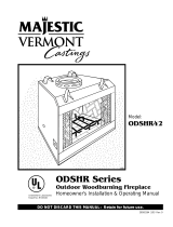
Ref. DVBR36 DVBR42
A 40” (1016 mm) 46” (1168 mm)
B 36” (614 mm) 36” (914 mm)
C 36” (914 mm) 42” (1067 mm)
D 23¹⁄₄” (591 mm) 23¹⁄₄” (591 mm)
E 6³⁄₈” (162 mm) 6³⁄₈” (162 mm)
F 6³⁄₈” (162 mm) 5³⁄₈” (137 mm)
G 20” (508 mm) 20” (508 mm)
H 22” (559 mm) 28” (711 mm)
I 13¹⁄₄” (337 mm) 13¹⁄₄” (337 mm)
J 3” (76 mm) 3” (76 mm)
K 6¹⁄₂” (165 mm) 6¹⁄₂” (165 mm)
L 29¹⁄₂” (749 mm) 29¹⁄₂” (749 mm)
M 30
¹⁄₄” (768 mm) 30¹⁄₄” (768 mm)
Framing Dimensions
N 40¹⁄₂” (1029 mm) 40¹⁄₂” (1029 mm)
O 41” (1041 mm) 47” (1194 mm)
P 20¹⁄₂” (521 mm) 20¹⁄₂” (521 mm)
Q 64
³⁄₄” (1645 mm) 69¹⁄₂” (1765 mm)
R 45³⁄₄” (1162 mm) 49” (1245 mm)
S 32³⁄₈” (822 mm) 35¹⁄₄” (895 mm)
Fireplace Dimensions (Installed as Rear Vent)
584
Specs - rear vent
2/14/02 djt
O - Rough Opening Width
Rough
Opening
Height
Rough
Opening
Depth
R
R
S
5/8” (16 mm)
Q
P
G
H
5/8” (16 mm)
E
D
F
N
B
A
C
J
K
Gas Line
Access
"
Electrical
Access
I
J
"
"
L
M
Fig. 3 Fireplace specifications and framing dimensions.

6
DVBR Series Direct Vent Gas Fireplace
20000584
Clearance to Combustibles
Appliance
Top ......................................................... 0” (0 mm)
Bottom ..................................................... 0” (0 mm)
Side ......................................................... 0” (0 mm)
Back ........................................................ 0” (0 mm)
Perpendicular Sidewall ........................... 0” (0 mm)
Top of unit to ceiling .......................... 36” (914 mm)
Front of unit to combustibles ............. 36” (914 mm)
Venting
Concentric sections of DV Vent ................... 1” (25 mm)
Nonconcentric sections of DV Vent
Sides and bottom ................................. 1” (25 mm)
Top ........................................................ 2” (51 mm)
Mantels
The height that a combustible mantel is fitted above the
fireplace is dependent on the depth of the mantel. This
also applies to the distance between the mantel leg (if
fitted) and the fireplace.
For the correct mounting height and widths, refer to
Figures 4a and 4b and the Mantel Chart below.
The distances and reference points are not affected by
the fitting of a bay window front trim kit.
Noncombustible mantels and legs may be installed at
any height and width around the appliance. When using
paint or lacquer, it must be heat resistant to prevent
discoloration.
J
F
G
H
I
Mantel
Leg
CFM164a
Mantel Leg Chart
06/22/01 sta
CFM170
DV Builder Front
View
O
N
M
L
K
CFM164a
Side of
Combustion Chamber
CFM170
Mantel Leg Mantel Leg from Side
Ref. Depth Ref. of Combusion Opening
F 14” (356 mm) K 14” (356 mm)
G 12” (305 mm) L 12” (305 mm)
H 10” (254 mm) M 10” (254 mm)
I 8” (203 mm) N 8” (203 mm)
J 4” (102 mm) O 3
¹⁄₂” (89 mm)
Fig. 4b Combustible mantel minimum installation.
Black
Surround Face
Mantel Chart
Mantel Mantel from Top
Ref. Shelf Depth Ref. of Comb. Chamber
V 14” (356 mm) A 18” (457 mm)
W 12” (305 mm) B 16” (406 mm)
X 10” (254 mm) C 14” (356 mm)
Y 8” (203 mm) D 12” (305 mm)
Z 1
¹⁄₂” (38 mm) E 8” (203 mm)
Fig. 4a Combustible mantel minimum installation.
A B C
D
E
V
W
X
Y
Z
Fireplace
CFM146
DV Mantel Chart
7/5/01 sta
Bottom of Door Trim
Top of Combustion
Chamber
CFM146a
Y
E
A
B
C
D
F
Y
B
X
LU584-1
Locating unit
2/4/99 djt
A) Flat on wall B) Cross corner C) **Island
D) *Room divider E) *Flat on wall corner F) Chase installation
Y) 6” minimum
Note (Fig. 1):
** Island (C) and Room Divider (D) installation is possible as long as
the horizontal portion of the vent system (X) does not exceed 20’ (610
cm). See details in Venting Section.
* When you install your fireplace in(D) Room divider or (E) Flat on
wall corner positions (Y), a minimum of 0” (0mm) clearance must be
maintained from the perpendicular wall and the front of the fireplace.
Fig. 1 Locating Gas Fireplace
LU584-1
Locating Your Fireplace

7
DVBR Series Direct Vent Gas Fireplace
20000584
Cold climate installation recommendation:
When installing this unit against a non-
insulated exterior wall or chase, it is
mandatory that the outer walls be insulated
to conform to applicable insulation codes.
Hearth
A hearth is not mandatory but is recommended for
aesthetic purposes. We recommend a noncombustible
hearth which projects out 12” (305 mm) or more from
the front of the fireplace.
Framing and Finishing
Check fireplace to make sure it is levelled
and properly positioned.
NOTE: If the optional Metro Face Kit (DVBR36 only)
is to be installed, the fireplace may be placed on a
4” (102 mm) raised platform. Raising the fireplace
will give the best aestethic appearance but is not
required.
To mount the appliance:
1. Choose the location.
2. Nailing flanges are supplied with the fireplace (found
on the fireplace hearth). To level the box and secure
it firmly in place, remove the nailing flanges from
the hearth and install at the sides of the fireplace as
shown in Figure 5.
FP549
nailing flange
1/05
Nail Top
Standoffs
Nail Side-
nailing
Flanges
FP549
Fig. 5 Nailing flanges.
Final Finishing
Noncombustible materials such as brick and tile can be
extended over the black face of the unit (Do not cover
the glass door.) If a Trim Kit is to be installed, brick and
tile will have to be installed flush with the side of this
appliance.
Gas Inlet & Manifold Pressures
Natural LP
Minimum Inlet Pressure 5.5” w.c. 11.0” w.c.
Maximum Inlet Pressure 14.0” w.c. 14.0” w.c.
Manifold Pressure 3.5” w.c. 10.0” w.c.
Gas Specifications
Max. Min.
Gas Input Input
Model Fuel Control B.T.U.H B.T.U.H.
DVBR36RN Natural Gas Millivolt Hi/Lo 24,000 16,000
DVBR36RP Propane Millivolt Hi/Lo 24,000 17,500
DVBR42RN Natural Gas Millivolt Hi/Lo 27,000 18,000
DVBR42RP Propane Millivolt Hi/Lo 27,000 19,700
DVBR36 / DVBR42
Certified to
ANSI Z21.88-2005 / CSA 2.33-2005
Vented Gas Fireplace Heater
Units: GFCN3J0, GFCN3M0
High Elevations
Input ratings are shown in BTU per hour and are
certified without deration for elevations up to
4,500 feet (1,370m) above sea level.
For elevations above 4,500 feet (1,370m) in USA,
installations must be in accordance with the
current ANSI Z223.1/NFPA 54 and/or local codes
having jurisdiction.
In Canada, please consult provincial and/or local
authorities having jurisdiction for installations at
elevations above 4,500 feet (1,370m).
Gas Line Installation
When purging gas line the front glass must
be removed.
The gas pipeline can be brought in through the right
side of the appliance. Knockouts are provided at con-
venient locations to allow for the gas pipe installation
and testing of any gas connection.
The gas line connection can be made with 3/8” copper
tubing, 1/2” rigid pipe or an approved flex connector.
Since some municipalities have additional local codes,
it is always best to consult your local authority and the
CSA-B149.1 installation codes. For US installations
consult the current National Fuel Gas Code, ANSI
Z223.1/NFPA 54.

8
DVBR Series Direct Vent Gas Fireplace
20000584
Always check for gas leaks with a mild
soap and water solution applied with a
brush no larger than 1” (25 mm). Never
apply soap and water solution with a spray
bottle. Do not use an open flame for leak
testing.
The fireplace valve must not be subjected
to any test pressures exceeding 1/2 psi.
Isolate or disconnect this or any other gas
appliance control from the gas line when
pressure testing.
The gas control is equipped with a captured screw type
pressure test point, therefore it is not necessary to pro-
vide a 1/8” test point up stream of the control.
When using copper or flex connector use only approved
fittings. Always provide a union when using black
iron pipe so the gas line can be easily disconnected for
burner or fan servicing. (Fig. 6) See the gas specifica-
tions for pressure details and ratings.
Fig. 9 EB-1 receptacle.
FP580
FP580
INSTA VENT FREE
EB1 JUNCTION BOX
11/18/97
OUTSIDE
ELECTRICAL BOX
INSIDE
FRONT OF UNIT
Remote Switch Installation
Do not wire the remote ON/OFF wall switch
for this gas appliance into a 120v power
supply.
1. Thread wire through the electrical knockout located
on either side of fireplace. Do not cut wire or insula
-
tion on metal edges. Ensure that wire is protected.
Run the other end to a conveniently located wall
receptacle box.
2. Attach wire to switch and install switch into recepta-
cle box. Attach cover plate to switch.
3. Connect wiring to gas valve. (Fig. 7)
W584-9
WIRING DIAGRAM
1/8/99 djt
11/9/99 added thermopile
Thermopile
Fig. 7 Remote switch wiring diagram for R models.
W584-9
Switch
Gas Valve
EB-1 Electrical Box
The fireplace, when installed, must be elec-
trically connected and grounded in accor-
dance with local codes or, in the absence
of local codes, with the current CSA C22.1
Canadian Electrical Code.
For USA installations, follow the local
codes and the national Electrical Code
ANSI/NFPA No. 70.
It is strongly suggested that the wiring of
the EB-1 Electrical Junction Box be carried
out by a licensed electrician.
Ensure that the power to the supply line
has been disconnected before commenc-
ing this procedure.
EB1 (Receptacle) Hook-Up
1. Remove contents from plastic bag. Remove knock-
out in center of electrical box. Remove coverplate
from fireplace and knockout. Insert connector
through coverplate, plate and box. Screw nut on
connector with screws provided (2) to secure the
coverplate to the plate.
2. Connect black positive wire to brass screw (polar
-
ized side) of receptacle. The white wire is connected
to chrome screw. The ground wire is connected to
green ground screw of the receptacle. Fit receptacle
into electrical box.
3. Screw cover plate provided to electrical box.
4. Secure receptacle to fireplace.
FP297A
INSTA VENT FREE
UVHB26 GAS SUPPLY
7/1/98
FP297A
Fig. 6 Typical gas supply installation.
1/2” Gas Supply
1/2” NPT X 1/2” Flare Shut-off Valve
3/8” Flex line
(from valve)

9
DVBR Series Direct Vent Gas Fireplace
20000584
Optional Top Vent Application
The DVBR36/42 fireplace is shipped as a rear vent unit.
If the layout requires a top vent, convert the unit follow-
ing the steps below.
DVBR36
1. Remove the eight (8) screws securing outer collar
adapter to fireplace. (Be careful not to damage insu-
lation.) (Fig. 10)
2. Set outer collar adapter aside.
DVT584-602
Outer Collar Adapter
Flue Pipe
3/11/99 djt
Flue Pipe
Remove
Screws (4)
Outer Collar
Adapter
Remove Screws (4)
DVT584-602
Rear View
Fig. 10 Remove screws from outer collar adapter.
6. Secure flue cover to back of flue outlet. Be sure to
replace gasket. (Fig. 12)
7. Install flue pipe to top of unit with four (4) screws. Be
sure to replace gasket. (Fig. 12)
8. Set insulation in back of unit foil side down.
9. Secure outer collar adapter to unit with the round
collar on top, secure with eight (8) screws.
NOTE: Be sure not to damage any gasket material.
3. Remove insulation on top of collector box. (Fig. 11)
4. Remove the four (4) screws securing flue cover to
top of unit and remove flue cover. (Fig. 11)
5. Remove the four (4) screws securing flue pipe to
back of unit. Remove flue pipe. (Fig. 11)
DVT584-603
Outer Collar Adapter
Flue Pipe
3/11/99 djt
Insulation
Remove
Screws (4)
Remove Screws
(4)
Flue
Cover
Flue
Pipe
DVT584-603
Fig. 11 Remove flue cover and flue pipe.
DVT584-604
Outer Collar Adapter
Flue Pipe
3/11/99 djt
Flue
Pipe
Foil Side
Replace
Screws
(4)
Insulation
Flue Pipe
DVT584-604
Fig. 12 Replace flue cover and flue pipe.
Replace
Screws (4)
DVT584-605
Outer Collar Adapter
Flue Pipe completed
3/11/99 djt
DVT584-605
Fig. 13 Completed conversion.

10
DVBR Series Direct Vent Gas Fireplace
20000584
FP1543
remove insulation
1/05
Remove Insulation
FP1543
Fig. b Remove and discard insulation.
Your fireplace is approved to be vented either through
the side wall, or vertical through the roof.
• Only CFM Corporation venting components spe-
cifically approved and labelled for this fireplace
may be used.
• Venting terminals shall not be recessed into a wall or
siding.
• Horizontal venting which incorporates the twist lock
pipe must be installed on a level plane without an
inclining or declining slope.
• Horizontal venting which incorporates the use of flex
venting shall have an inclining slope from the unit of
1/2” (13 mm) per12” (305 mm).
There must not be any obstruction such as bushes,
garden sheds, fences, decks or utility buildings within
24” from the front of the termination hood.
Do not locate termination hood where excessive snow
or ice build up may occur. Be sure to check vent termi-
nation area after snow falls, and clear to prevent ac-
cidental blockage of venting system. When using snow
blowers, make sure snow is not directed towards vent
termination area.
Location of Vent Termination
It is imperative the vent termination be located observ-
ing the minimum clearances as shown on the following
page.
General Venting
DVBR42
1. Remove the seven (7) screws securing the heat
shield cover plate to the fireplace. (Fig. a) Discard
the heat shield cover plate.
FP1542
DVBR42 heat shld
cover plate
1/05
Remove Screws (7)
Heat Shield
Cover Plate
FP1542
Fig. a Remove screws securing heat shield cover plate. Dis-
card cover plate.
2. Carefully remove the square piece of insulation
along the perforations. (Fig. b) Discard insulation.
3. Remove the eight (8) screws securing outer collar
adapter to fireplace. (Be careful not to damage insu-
lation.) (Fig. 10)
4. Set outer collar adapter aside.
5. Remove insulation on top of collector box. (Fig. 11)
6. Remove the four (4) screws securing flue cover to
top of unit and remove flue cover. (Fig. 11)
7. Remove the four (4) screws securing flue pipe to
back of unit. Remove flue pipe. (Fig. 11)
8. Secure flue cover to back of flue outlet. Be sure to
replace gasket. (Fig. 12)
9. Install flue pipe to top of unit with four (4) screws. Be
sure to replace gasket. (Fig. 12)
10. Set insulation in back of unit foil side down.
11. Secure outer collar adapter to unit with the round
collar on top, secure with eight (8) screws.
NOTE: Be sure not to damage any gasket material.

11
DVBR Series Direct Vent Gas Fireplace
20000584
Canadian Installations
1
US Installations
2
V
V
V
V
V
V
V
X
X
X
D
E
B
B
B
C
B
M
B
A
J
K
F
L
VENT TERMINATION AIR SUPPLY INLET
AREA WHERE TERMINAL IS NOT PERMITTED
H
I
Operable
Operable
Fixed
Closed
V
B
CFM145a
DV Termin Location
5/01/01 Rev. 12/05/01
sta
INSIDE
CORNER DETAIL
V
A
G
N
N
CFM145a
General Venting Information - Termination Location
A = Clearance above grade, veranda, porch, 12” (30cm) 12” (30cm)
deck, or balcony
B = Clearance to window or door that may be 6” (15cm) for appliances 6” (15cm) for appliances
opened < 10,000Btuh (3kW), 12” (30cm) < 10,000 Btuh (3kW), 9”
for appliances > 10,000 Btuh (3kW) and (23cm) for appliances > 10,000
< 100,000 Btuh (30kW), 36” (91cm) Btuh (3kW) and < 50,000 Btuh
for appliances > 100,000 Btuh (30kW) (15kW), 12” (30cm) for
appliances > 50,000 Btuh (15kW)
C = Clearance to permanently closed window 12” (305mm) recommended to 12” (305mm) recommended to
prevent window condensation prevent window condensation
D = Vertical clearance to ventilated soffit located
above the terminal within a horizontal 18” (458mm) 18” (458mm)
distance of 2 feet (610mm) from the center
line of the terminal
E = Clearance to unventilated soffit 12” (305mm) 12” (305mm)
F = Clearance to outside corner see next page see next page
G = Clearance to inside corner (see next page) see next page see next page
H = Clearance to each inside of center line 3’ (91cm) within a height of 15’ (5m) 3’ (91cm) within a height of 15’
extended above meter/regulator assembly above the meter/regulator assembly (5m) above the meter/regulator
assy
I = Clearance to service regulator vent outlet 3’ (91cm) 3’ (91cm)
J = Clearance to nonmechanical air supply inlet 6” (15cm) for appliances < 10,000 6” (15cm) for appliances
to building or the combustion air inlet to any Btuh (3kW), 12” (30cm) for < 10,000 Btuh (3kW), 9”
other appliances appliances > 10,000 Btuh (3kW) and (23cm) for appliances > 10,000
< 100,000 Btuh (30kW), 36” (91cm) Btuh (3kW) and < 50,000 Btuh
for appliances > 100,000 Btuh (30kW) (15kW), 12” (30cm) for
appliances > 50,000 Btuh (15kW)
K = Clearance to a mechanical air supply inlet 6’ (1.83m) 3’ (91cm) above if within 10’
(3m) horizontally
L = Clearance above paved sidewalk or paved 7’ (2.13m)† 7’ (2.13m)†
driveway located on public property
M = Clearance under veranda, porch, deck or 12” (30cm)‡ 12” (30cm)‡
balcony
N = Clearance above a roof shall extend a minimum of 24” (610mm) above the highest point when it passes through the roof
surface, and any other obstruction within a horizontal distance of 18” (450mm).
1 In accordance with the current CSA-B149 Installation Codes
2 In accordance with the current ANSI Z223.1/NFPA 54 National Fuel Gas Codes
† A vent shall not terminate directly above a sidewalk or paved driveway which is located between two single family dwellings and
serves both dwellings
‡ only permitted if veranda, porch, deck or balcony is fully open on a minimum 2 sides beneath the floor:
NOTE: 1. Local codes or regulations may require different clearances.
2. The special venting system used on Direct Vent appliances are certified as part of the appliance, with clearances tested and
approved by the listing agency.
3. CFM Corporation assumes no responsibility for the improper performance of the appliance when the venting system does not
meet these requirements.
Fig. 14 Vent termination clearances.

12
DVBR Series Direct Vent Gas Fireplace
20000584
General Information Assembling Vent Pipes
Flex Vent Pipes
Before joining the flex vent pipe to the unit, apply a
bead of high temperature sealant* (provided) to the 4”
pipe exiting the fireplace. Secure flex vent pipe in place
with a hose clamp (provided).
*Be sure the flex pipe overlaps at least 1” (25mm) onto
the collars of the fireplace and termination. If the ter-
mination has an internal bead, be sure to overlap and
secure 1” (25 mm) past the bead.
FP1471
flex vent
Apply High Temperature
Sealant
Hose Clamp
FP1471
Fig. 16 Apply high temperature sealant to 4” and 7” pipes.
Canadian Installations
The venting system must be installed in accordance
with the current CSA-B149.1 installation code.
USA Installations
The venting system must conform to local codes and/or
the current National Fuel Code ANSI Z223.1/NFPA 54.
Only venting components manufactured by CFM Corpo
-
ration may be used in Direct Vent systems.
* Be sure the vent is actually crushed before proceed-
ing. Apply a tug to be sure the vent will not slip off the
collars.
Repeat process with 7” flex vent pipe. The same proce-
dure must be performed on the vent side.
Fig. 15 Termination clearances.
Outside Corner
Inside Corner
Termination Clearances
Termination clearances for buildings with combustible and noncombustible exteriors.
G =
Combustible
6" (152 mm)
Noncombustible
2" (51 mm)
F =
Combustible
6" (152 mm)
Noncombustible
2" (51 mm)
G
Balcony -
with no side wall
M =
Combustible &
Noncombustible
12" (305 mm)
M
Balcony -
with perpendicular side wall
M = 24" (610 mm)
P = 20” (508 mm)
M
F
Alcove Applications*
C
D
C
E
V
V
Combustible &
Noncombustible
V
V
V
E = Min. 6” (152 mm) for
non-vinyl sidewalls
Min. 12” (305 mm) for
vinyl sidewalls
O = 8’ (2.4 m) Min.
O
P
584-15
No.
of Caps D
Min.
C
Max.
1 3’ (.9 mm) 2 x D
Actual
2 6’ (1.8 m) 1 x D
Actual
3 9’ (2.7 m) 2/3 x D
Actual
4 12’ (3.7 m) 1/2 x D
Actual
D
Min.
= # of Termination caps x 3
C
Max.
= (2 / # termination caps) x D
Actual
*NOTE: Termination in an alcove space (spaces open only on one side and with an overhang) is permitted with the dimensions
specified for vinyl or non-vinyl siding and soffits. 1. There must be a 3’ (914 mm) minimum between termination caps. 2. All
mechanical air intakes within 10’ (1 m) of a termination cap must be a minimum of 3’ (914 mm) below the termination cap. 3. All
gravity air intakes within 3’ (914 mm) of a termination cap must be a minimum of 1’ (305 mm) below the termination cap.

13
DVBR Series Direct Vent Gas Fireplace
20000584
TWL100
Twist Lock Pipe
3/12/99 djt
Male End
Female
End
Screw Holes
TWL100
Fig. 17 Twist-Lock pipe joints.
Twist Lock Pipes
When using CFM Corporation twist-lock pipe, it is not
necessary to use silicone to seal the twist-lock joints.
The only areas that need silicone are the collars on the
fireplace, the telescoping pipe (if used) and the hori-
zontal termination connection (when necessary). The
female (flared) end secures to the fireplace first with the
male end away from the fireplace.
To join the pipes together, simply align the beads of the
male end with the grooves of the female end, twisting
the pipe until the flange on the female end touches the
external bead on the male end. Secure the joints with
three (3) sheet metal screws. (Fig. 17)
To make assembly easier, apply lubricant (vaseline or
similar) on the male end of the twist-lock pipe.
How to Use the Vent Graph
The Vent Graph should be read in conjunction with the
following vent installation instructions to determine the
relationship between the vertical and horizontal dimen-
sions to the vent system.
1. Determine the height of the center of the horizontal
vent pipe exiting through the outer wall. Using this
dimension on the Sidewall Vent Graph (Fig. 18),
locate the point intersecting with the slanted graph
line.
2. From the point of this intersection, draw a vertical
line to the bottom of the graph.
3. Select the indicated dimension, and position the
fireplace in accordance with same.
EXAMPLE A:
If the vertical dimension from the floor of the unit is 11
feet (3352 mm) the horizontal run to the face of the
outer wall must not exceed 14’ (4267 mm).
EXAMPLE B:
If the vertical dimension from the floor of the unit is 7’
(2133mm), the horizontal run to the face of the outer
wall must not exceed 8¹⁄₂’ (2590 mm).
Rear Wall Vent Applications
When installed as a rear vent unit this appliance may be
vented directly to a termination located on the rear wall
behind the appliance.
• Only CFM Corporation venting components are ap-
proved to be used in these applications (See ‘Venting
Components’ listed for different installation require-
ments).
• The maximum horizontal distance between the rear
of the appliance (or end of the transition elbow in a
corner application) and the outside face of the rear
wall is 20” (508mm). (Fig. 19, 20 )
• Only one 45° elbow is allowed in these installations.
• Minimum clearances between vent pipe and com-
bustible materials are as follows:
Top - 2” (51 mm)
Sides - 1” (25 mm)
Bottom - 1” (25 mm)
Refer to Page 19 for venting
requirements for snorkels.
Vertical Dimension from the Floor of the Unit
to the Center of the Horizontal Vent Pipe
Fig. 18 Sidewall venting graph. (Dimensions in feet.)
DV Graph
3
4
5
6
7
8
9
10
11
12
13
14
15
16
17
18
19
20
21
22
23
24
25
26
27
28
29
30
3
4 5 6 7 8 9 10 11 12 13 14 15 16 17 18 19 20
eg: A
eg: B
Horizontal Dimension from the Outside Face of the
Wall to the Center of the Fireplace Vent Flange

14
DVBR Series Direct Vent Gas Fireplace
20000584
Rear Wall Vent Installations -
Twist Lock Pipe
Step 1
Locate and cut the vent opening in the wall.
For combustible walls first frame in opening. (Fig. 21)
NOTE: When using flex vent, the opening will have to
be measured according to the 1” (25 mm) rise in 24”
(610 mm) vertical run.
Combustible Walls:
Cut a 10³⁄₈”H x 9³⁄₈” W (265 mm
x 240 mm) hole through the exterior wall and frame as
shown. (Fig. 21)
Noncombustible Walls:
Hole opening should be 7¹⁄₂”
(191 mm) diameter.
Zero clearance sleeve is only required for
combustible walls.
Step 2
Measure wall thickness and cut zero clearance sleeve
parts to proper length (Maximum 12” / 305mm). As-
semble sleeve to its maximum opening (10³⁄₈” x 9³₈”)
and attach to firestop assembly. (Fig. 22)
Step 3
Measure the horizontal length requirement for the vent-
ing including a 2” (51 mm) overlap, i.e. from the elbow
to the outside wall face plus 2” (51 mm). (Fig. 20)
Step 4
Install the 4” (102 mm) vent to the appliance collar and
secure with three (3) sheet metal screws. Install the 7”
(175 mm) vent pipe to the appliance collar and secure
with three (3) sheet metal screws. It is not necessary to
seal this connection. If a 45° elbow is being used attach
the elbow to the appliance in the same manner then at-
tach the venting to the elbow.
It is critical that there is no downward
slope away from the appliance when con-
necting the vent or elbow.
Step 5
Guide the venting through the vent hole as you place
the appliance in its installed position. Guide the 4”
(102 mm) and 7” (175 mm) collar of the vent termina-
tion into the outer ends of the venting. Do not force
the termination. If the vent pipes do not align with the
termination, remove and realign the venting at the appli-
ance flue collars. (Fig. 23) Attach the termination to the
wall as outlined in the instruction sheet supplied with
the termination.
VO584-100
Vent Opening
2/99 djt
Fig. 21 Locate vent opening on wall.
Framing
Detail
9³⁄₈"
(240 mm)
10³⁄₈"
(265 mm)
Fireplace Hearth
7¹⁄₂" Dia.
(191 mm)
Vent Opening - Noncombustible Wall
Fireplace Hearth
VO584-100
Vent Opening - Combustible Wall
CFM135
Zero Clearance Sleeve
2/26/01 sta
#8 Screws
(2)
Adjustable Zero
Clearance Sleeve
Firestop
#8 Screws (2)
#8 Screws (2)
Max. Length
12” (294 mm)
Fig. 22 Adjustable zero clearance sleeve.
CFM135a
FP1188
Fig. 19 Rear vent application, no elbows.
20” (506 mm)
Max.
Top View Flat Installation
Fig. 20 Rear vent application, one 45° elbow.
Top View Corner Installation
FP1188
20” (506 mm)
Max.

15
DVBR Series Direct Vent Gas Fireplace
20000584
FP1005
Side View Vent Termination
1/25/00 djt
Finished
Wall
Vent
Termination
Fig. 23 Side view of final unit location, twist lock pipe.
FP1005
These ends should
be even
These ends
screwed to appli-
ance
1/2" (13mm)
12" (305mm)
FP1472
rise in length
4/04 djt
FP1472
Fig. 25 There must be a 1” rise in 24” length.
Install the 7” vent pipe in the same manner as Step 2.
NOTE: There must be a 1” (25 mm) rise in 24”
(610 mm) length of flex vent.
Step 4
Assemble the flex vent to the collars on the termination
as you did on the appliance.
Rear Wall Vent Installations -
Flex Vent Pipe
Follow Steps 1 and 2 on Page 14.
Step 3
Install the 4” (102 mm) flex vent pipe to the appliance
collars described in “General Information Assembling
Vent Pipes”, Page 12. If the installation requires a 45°
angle, grasp the vent pipe close to the appliance collar
and bend to 45°. DO NOT exceed 45°. (Fig. 24)
FP1473
corner flex install
4/04 djt
Termination
Flex Section
Appliance Collars
FP1473
Fig. 24 Grasp the vent pipe close to the collar and bend to
45° angle. Do not exceed 45°.
Vertical Sidewall Applications
Since it is very important that the venting system
maintain its balance between the combustion air
intake and the flue gas exhaust, certain limitations
as to vent configurations apply and must be strictly
adhered to.
The Vent Graph, showing the relationship between ver
-
tical and horizontal side wall venting, will help to deter-
mine the various dimensions allowable.
Minimum clearance between vent pipes and com-
bustible materials is 1” (25 mm) on top, bottom and
sides unless otherwise noted.
When vent termination exits through foundations less
than 20” (508mm) below siding outcrop, the vent pipe
must flush up with the siding.
It is best to locate the fireplace in such a way that mini
-
mizes the number of offsets and horizontal vent length.
The horizontal vent run refers to the total length of vent
pipe from the flue collar of the fireplace (or the top of
the Transition Elbow) to the face of the outer wall.
Horizontal plane means no vertical rise exists on this
portion of the vent assembly.
When installing the appliance as a rear
vent unit, the 90° or 45° Transition Elbow
attached directly to the rear of the unit is
NOT INCLUDED in the following criteria
and calculations, and unless specifically
mentioned should be ignored when calcu-
lating venting layouts.
• The maximum number of 90° elbows per side wall
installation is three (3). (Fig. 26)
• If a 90° elbow is fitted directly on top of the fireplace
flange the maximum horizontal vent run before the
termination or a vertical rise is 36” (914mm). (Fig.
27)

16
DVBR Series Direct Vent Gas Fireplace
20000584
V584-201
Horizontal Run
2/99 djt
10’
(254cm)
7’
(178cm)
8’
(244cm)
A
B
A + B = 17’ Max.
V584-201
Fig. 29 Maximum vent run with elbows.
In Figure 28 & 29, dimension A plus B must not be
greater than 17’ (5.2m)
• The maximum number of 45° elbows permitted per
side wall installation is two (2). These elbows can be
installed in either the vertical or horizontal run.
• For each 45° elbow installed in the horizontal run,
the length of the horizontal run MUST be reduced by
18” (457mm). This does not apply if the 45° elbows
are installed on the vertical part of the vent system.
• The maximum number of elbow degrees in a system
is 270°. (Fig. 30)
Example:
Elbow 1 = 90°
Elbow 2 = 45°
Elbow 3 = 45°
Elbow 4 = 90°
Total angular variation = 270°
1
2
3
4
1
2
3
4
1 + 2 + 3 + 4 = 270°
FP1180
Fig. 30 Maximum elbow usage.
3 x 90°
Elbows
3 x 90°
Elbows
FP1176
Fig. 26 Maximum three (3) 90° elbows per installation.
Max 20"
Max 20"
36"
(914mm)
Max.
36"
(914mm)
Max.
FP1177
Fig. 27 Maximum horizontal runwith no rise.
7'6"
A
B
90
o
A + B = 17' (Max.)
FP1178
Fig. 28 Horizontal run reduction.
• If a 90° elbow is used in the horizontal vent run
(level height maintained) the horizontal vent length
is reduced by 36” (914mm). (Fig. 28, 29) This does
not apply if the 90° elbows are used to increase or
redirect a vertical rise. (Fig. 26)
Example: According to the vent graph (Page 15) the
maximum horizontal vent length in a system with a
7¹⁄₂” (191mm) rise is 20” (508mm) and if a 90° elbow is
required in the horizontal vent it must be reduced to 17’
(5.2m).

17
DVBR Series Direct Vent Gas Fireplace
20000584
Vertical Sidewall Installation
Twist Lock Pipe
Step 1
Locate vent opening on the wall. It may be necessary
to first position the fireplace and measure to obtain hole
location. Depending on whether the wall is combustible
or noncombustible, cut opening to size. (Fig. 31) (For
combustible walls first frame in opening.)
NOTE: When using flex vent, the opening will have to
be measured according to the 1” (25 mm) rise in 24”
(610 mm) vent run.
Combustible Walls:
Cut a 9³⁄₈”H x 9³⁄₈”W (238mm x
238mm) hole through the exterior wall and frame as
shown. (Fig. 31)
Noncombustible Walls:
Hole opening must be 7¹⁄₂”
(191 mm) in diameter.
Step 2
Measure wall thickness and cut zero clearance sleeve
parts to proper length (MAXIMUM 12” / 305mm). As-
semble sleeve and attach to firestop with #8 sheet
metal screws (supplied). Install firestop assembly. (Fig.
29)
Zero clearance sleeve is only required for
combustible walls.
VO584-100
Vent Opening
2/99 djt
Vent Opening Combustible Wall
9³⁄₈”
(240mm)
9³⁄₈”
(240mm)
Fireplace Hearth
Framing Detail
Vent Opening Non-
combustible Wall
7¹⁄₂” Dia.
(190mm)
Fireplace Hearth
VO584-100
Fig. 31 Locate vent opening on wall.
Step 3
Place fireplace into position. Measure the vertical height
(X) required from the base of the flue collars to the cen-
ter of the wall opening. (Fig. 33)
Step 4
Apply a band of silicone to the inner and outer flue
collars of the fireplace and using appropriate length of
pipe section(s) attach to fireplace with three (3) screws.
Follow with the installation of the inner and outer elbow,
again secure joints as described in the “Connecting
Vent Pipe” section.
CFM135
Zero Clearance Sleeve
2/26/01 sta
#8 Screws
(2)
Adjustable Zero
Clearance Sleeve
Firestop
#8 Screws (2)
#8 Screws (2)
Max. Length
12” (294 mm)
Fig. 32 Adjustable zero clearance sleeve.
CFM135a
X
X
FP1181
Fig. 33 Vertical height requirements.
Step 5
Measure the horizontal length requirement including a
2” (50mm) overlap, i.e. from the elbow to the outside
wall face plus 2” (50mm) (or the distance required if
installing a second 90° elbow). (Fig. 34)
Always install horizontal venting on a level
plane.
Step 6
Use appropriate length of pipe sections - telescopic or
fixed - and install. The sections which go through the
wall are packaged with the starter kit, and can be cut to
suit if necessary.

18
DVBR Series Direct Vent Gas Fireplace
20000584
X
X
FP1182
Fig. 34 Horizontal length requirement.
Sealing vent pipe and firestop gaps with high tem-
perature sealant will restrict cold air being drawn in
around fireplace.
Step 7
Apply high temperature sealant to 4” (102 mm) and
7” (175 mm) collars or the termination one inch away
from crimped end. Guide the vent terminations 4” and
7” collars into their respective vent pipes. Double check
that the vent pipes overlap the collars by 2” (51 mm).
Secure the termination to the wall with screws provided
and caulk around the wall plate to weatherproof. As an
alternative to screwing the termination directly to the
wall, you may also use expanding plugs or an approved
exterior construction adhesive. You may also attach the
termination with screws through the inner body into the
4” vent pipe, however for this method, you must extend
the 4” pipe approximately 6” (152 mm) beyond the outer
face of the wall.
Support horizontal pipes every 3’ (91 cm)
with metal pipe straps.
Vertical Sidewall Installation
Flex Vent Pipe
NOTE: The 40” (1016 mm) flex vent is used for 90° off
the top of the unit then out the back wall.
Follow Step 1 and 2 on Page 17.
Step 3
Install the four (4) spacer springs on the 4” flex vent
pipe. When installing the spacer springs around the 4”
pipe, stretch the spring to approximately 15” (381 mm),
wrap the spring around the pipe and interlock the ends
of the spacer spring approximately 2” (51 mm). Measure
6³⁄₄” (172 mm) from the end of the pipe. Place
the next
12"
(305mm)
6"
(152mm)
5"
(127mm)
6"
(172mm)
FP1474
spacer springs
4/04 djt
4” Flex Vent
Pipe
Spacer
Spring
FP1474
Fig. 35 Install spacer springs.
spring 5” (127 mm) from the previously installed spring.
Place the next spring 6” (152 mm) from the last spring.
Finally place the last spring 12” (305 mm) from the last
spring installed. (Fig. 35)
6" (165mm)
FP1475
flex 90 bend
4/04 djt
FP1475
Fig. 36 Bend flex vent at 90° so horizontal portion is 6¹⁄₂”
(165 mm) off top of unit.
Step 4
Install the 4” (102 mm) flex vent pipe to the appliance
collar as described on Page 12. Secure the end with the
first spring 6³⁄₄” (172 mm) from the flex pipe end to the
unit.
Step 5
Slide the 7” (178 mm) flex vent pipe over the 4” flex
vent pipe and secure the 7” collar as described on Page
12.
Step 6
Bend the flex pipe horizontal so the bottom of the
horizontal pipe measure 6¹⁄₂” (165 mm) from the top of
the unit immediately after the 90° formation. (Fig. 36)
Be sure to follow the 1” (25 mm) rise in a 24” (610 mm)
horizontal run rule.
Step 7
Install the 4” flex then 7” flex to the termination.

19
DVBR Series Direct Vent Gas Fireplace
20000584
Do not back fill around snorkel.
A clearance of at least 4” must be main
-
tained between the snorkel and the soil.
If the foundation is recessed, use recess brackets (not
supplied) for securing lower portion of the snorkel. Fas-
ten brackets to wall first, then secure to snorkel with self
drilling #8 x 1/2 sheet metal screws. It will be necessary
to extend vent pipes out as far as the protruding wall
face. (Fig. 38)
Below Grade Installation
When it is not possible to meet the required vent terminal
clearances of 12” (305 mm) above grade level, a snorkel
kit is recommended. It allows installation depth down
to 7” (178 mm) below grade level. The 7” (178 mm) is
measured from the center of the horizontal vent pipe as it
penetrates through the wall.
Ensure the sidewall venting clearances are ob-
served. If venting system is installed below ground,
we recommend a window well with adequate and
proper drainage to be installed around the termina-
tion area.
If installing a snorkel, a minimum 24” (610 mm) vertical
rise is necessary. The maximum horizontal run with the
24” vertical pipe is 36” (914 mm). This measurement
is taken from the collar of the fireplace (or transition
elbow) to the face of the exterior wall. See the Sidewall
Venting Graph for extended horizontal run if the vertical
exceeds 24” (610 mm).
1. Establish vent hole through the wall (Fig. 31)
2. Remove soil to a depth of approximately 16”
(406mm) below base of snorkel. Install drain pipe.
Install window well (not supplied). Refill hole with 12”
(305mm) of coarse gravel leaving a clearance of ap-
proximately 4” (102 mm) below snorkel. (Fig. 37)
3. Install vent system.
4. Ensure a watertight seal is made around the vent
pipe coming through the wall.
5. Apply high temperature sealant caulking (supplied)
around the 4” and 7” snorkel collars.
6. Slide the snorkel into the vent pipes and secure to
the wall.
7. Level the soil so as to maintain a 4” (102 mm) clear
-
ance below snorkel. (Fig. 37)
BG400
Below grade installation
2/10/99 djt
10/19/99 added standoffs
Fig. 37 Below grade installation.
Zero Clearance
Sleeve if Required
Firestop
7” Pipe
7DVSK (Snor-
kel)
4” Clearance
Min.
Window
Well
Gravel
Drain
Foundation Wall
* A minimum of 24” (608
mm) vertical pipe must be
installed when using the
7TDVSKS kit.
BG400
BG401
Snorkel
2/10/99 djt
Foundation Recess
Snorkel
Watertight Seal
Around Pipe
Wall Screws
Sheet Metal
Screws
BG401
Fig. 38 Snorkel installation, recessed foundation.
Vertical Through-the-Roof Applications
This gas fireplace has been approved for:
• Vertical installations up to 40’ (12m) in height. Up
to a 10’ (3 m) horizontal vent run can be installed
within the vent system using a maximum of two 90°
elbows. (Fig. 41)
• Up to two 45° elbows may be used within the hori-
zontal run. For each 45° elbow used on the horizon-
tal plane, the maximum horizontal length must be
reduced by 18” (450mm).
Example: Maximum horizontal length:
No elbows = 10’ (3 m)
1 x 45° elbow = 8.5’ (2.6 m)
2 x 45° elbows = 7’ (2.1 m)
• A minimum of an 8’ (2.5 m) vertical rise is required.
• Two sets of 45° elbow offsets may be used within the
vertical sections. From 0 to a maximum of 8’ (2.5 m)
of vent pipe can be used between elbows. (Fig. 42)
• 7DVCS supports offsets. (Fig. 44) This application
will require that you first determine the roof pitch
and use the appropriate starter kit. (Refer to Venting
Components List)
• The maximum angular variation allowed in the sys-
tem is 270°. (Fig. 42)
• The minimum height of the vent above the highest
point of penetration through the roof is 2’ (610mm).
(Fig. 45) Refer to Note 2, Page 11.

20
DVBR Series Direct Vent Gas Fireplace
20000584
1
2
3
4
1
2
3
4
1 + 2 + 3 + 4 = 270°
FP1179
Fig. 42 Maximum elbow usage.
FP1184
Typical roof/ceiling
support apps.
FP1184
Typical Roof
Support Ap-
plication
Typical Ceiling Sup
-
port Application
Fig. 44 Venting supports.
Joist
Attic Insulation Shield
Ceiling
Installation
Upper Floor
11”
Firestop
Spacer
Nails (4)
Fig. 43 Place firestop spacer(s) and secure.
VR404
11”
5. Place firestop(s) #7DVFS into position and secure.
(Fig. 43)
6. Install roof support (Fig. 44) and roof flashing
making sure upper flange of flashing is below the
shingles. (Fig. 46)
7. Install appropriate pipe sections until above the
flashing. (Fig. 46)
8. Install storm collar and seal around the pipe.
9. Add additional vent lengths for proper height.
10. Apply high temperature sealant to 4” and 7” collars
of vent termination and install.
If there is a room above ceiling level, firestop spacers
must be installed on both the bottom and the top side
of the ceiling joists. If an attic is above ceiling level
a 7DVAIS (Attic Insulation Shield) must be installed.
The enlarged ends of the vent section always face
downward.
Vertical Through-the-Roof Installation
Max. Height 40’ (12.2m)
Min. Height 8’ (2.4m)
Max. 10’ (3m)
FP1183
Max. Height
40’ (12.2m)
Min. Height 8’
(2.4m)
Max. 10’ (3m)
Fig. 41 Support straps for horizontal runs.
1. Locate your fireplace.
2. Plumb to center of the (4”) 90° transition elbow
(7DVRT90) from ceiling above and mark position.
3. Cut opening equal to 9³⁄₈" x 9³⁄₈" (240 x 240 mm).
4. Proceed to plumb for additional openings through
the roof. In all cases, the opening must provide a
minimum of 1” (25 mm) clearance to the vent pipe,
i.e., the hole must be a minimum of 9³⁄₈" x 9³⁄₈" (240
x 240 mm).
/