Page is loading ...

Service Manual
Residential Mobile Home Small Package Products
Air Conditioners and Heat Pumps
Using R---410A R efr iger ant
TABLE OF CONTENTS
PAGE
SAFETY CONSIDERATIONS 2.........................
INTRODUCTION 2...................................
INSTALLATION GUIDELINE 2........................
ACCESSORY DESCRIPTIONS 2........................
LOW-- AMBIENT COOLING GUIDELINE 3...............
CABINET ASSEMBLY & COMPONENTS 3...............
ELECTRICAL 9 -- 10...................................
Aluminum Wire 9..................................
Contactor 9.......................................
Capacitor 9.......................................
Cycle Protector 10..................................
Crankcase Heater 10................................
PRESSURE SWITCHES 10 -- 10..........................
Low--Pressure Switch 10..........................
High--Pressure Switch (AC & HP) 10................
Loss Of Charge Switch (HP only) 10................
DEFROST THERMOSTAT 11..........................
DEFROST CONTROL BOARD 11--11....................
Defrost Control 11..............................
COPELAND SCROLL, DANFOSS SCROLL ,
LG SCROLL 14 --15...................................
Compressor Failures 15..............................
Mechanical Failures 15..............................
Electrical Failures 15................................
RECIPROCATING COMPRESSOR 16 --19................
Mechanical Failures 16..............................
Electrical Failures 17................................
FAN MOTOR 19......................................
COMPRESSOR PLUG 19..............................
LOW--VOLTAGE TERMINALS 19.......................
REFRIGERATION SYSTEM 20 -- 23......................
Refrigerant 20.....................................
Compressor Oil 20..................................
Brazing 20........................................
Liquid Line Filter Drier 22...........................
Suction Line Filter Drier 22...........................
Accumulator 22....................................
Thermostatic Expansion Valve (TXV) 23................
024-- 048 A/C and Heat Pump
060 A/C & 13 SEER Heat Pump
A10165
060 14 SEER Heat Pump
A150067
Fig. 1 – A/C and Heat Pump
PAGE
PISTON BODY CLEANING OR REPLACEMENT 24.......
REFRIGERATION SYSTEM REPAIR 24..................
Leak Detection 24..................................
Coil Removal 25...................................
Compressor Removal and Replacement 25...............
System Clean--Up After Burnout 25....................
Evacuation 26.....................................

2
CHECK CHARGE 26..................................
TROUBLESHOOTING WITH SUPERHEAT 27.............
INDOOR AIRFLOW AND AIRFLOW ADJUSTMENTS 28 --30
Refrigerant 28.....................................
Heating Check Charge Procedure 28....................
Sequence of Operation 30............................
ECM FAN MOTOR TROUBLESHOOTING 30 --31..........
Time Delays 31....................................
Pressure Switches 31................................
Accumulator, Reversing Valve (RVS) 31.................
Control Box 31....................................
CARE AND MAINTENANCE 37........................
R-- 410A QUICK REFERENCE GUIDE 38.................
INDEX OF TABLES 43................................
SAFETY CONSIDERATIONS
Installation, service, and repair of these units should be attempted
only by trained service technicians familiar with standard service
instruction and training material.
All equipment should be installed in accordance with accepted
practices and unit Installation Instructions, and in compliance with
all national and local codes. Power should be turned off when
servicing or repairing electrical components. Extreme caution
should be observed when troubleshooting electrical components
with power on. Observe all warning notices posted on equipment
and in instructions or manuals.
UNIT OPERATION AND SAFETY HAZARD
Failure to follow this warning could result in personal
injury or equipment damage.
R--410A systems operate at higher pressures than standard
R--22 systems. Do not use R --22 service equipment or
components on these R--410A units. Ensure service
equipment is rated for R--410A.
!
WARNING
Refrigeration systems contain refrigerant under pressure. Extreme
caution should be observed when handling refrigerants. Wear
safety glasses and gloves to prevent personal injury. During normal
system operations, some components are hot and can cause burns.
Rotating fan blades can cause personal injury. Appropriate safety
considerations are posted throughout this manual where potentially
dangerous techniques are addressed.
Follow all safety codes. Wear safety glasses, protective clothing,
and work gloves. Have a fire extinguisher available. Read these
instructions thoroughly and follow all warnings or cautions
included in literature and attached to the unit. Consult local
building codes, the current editions of the National Electrical Code
(NEC) NFPA 70 and NFPA 90B--Installation Warm Air Heating
and A/C Systems (Residential).
In Canada refer to the current editions of the Canadian Electrical
Code CSA C22.1.
INTRODUCTION
This document provides required system information necessary to
install, service, repair or maintain the small package products (SPP)
air conditioners and heat pumps using R-- 410A refrigerant.
Refer to the unit Product Data/Technical specifications for rating
information, electrical data, required clearances, additional
component part numbers and related pre-- sale data. Installation
Instructions are also available per specific models.
Information in this document refers to units produced in 2010 to
current.
INSTALLATION GUIDELINE
Residential New Construction
Specifications for these units in the residential new construction
market require the unit to be installed outdoors and meet all local
code and requirements. Consult the Installation Instructions for any
additional installation detail.
Add--On Replacement (Retrofit)
Specifications for these units in the add--on replacement/retrofit
market require the unit to be installed outdoors and meet all local
codes and requirements. Clearances, power supply, system static
needs to be check to ensure that the replacement unit can perform
within the design parameter desired specified in the Product Data.
ACCESSORIES
Table 1—Required Field--Installed Accessories for Air
Conditioners and Heat Pumps
Accessory
Required for
low ambient
cooling
applications
(Below 40° F /
4.4° C)
Accessory Part
Number
Motormaster II Low
Ambient Kit
Yes CPLOWAMB001A00
Evaporator Freeze
Thermostat
Recommended KSAFT0101AAA
Compressor Start
Assist (CTCR)
Yes CPHSTART002A00
Isolation Relay
(Required for Heat
Pumps)
Yes --HN--65KJ-016
Crankcase Heater --- --- See below...
-- AC 13 SEER 24---42
Yes CPCRKHTR007A00
-- AC 14 SEER 24---36
-- AC 13 SEER 48---60
Yes CPCRKHTR004A00
-- AC 14 SEER 42---60
-- HP 13 SEER 42 --- 60
-- HP 14 SEER 42 --- 60
-- HP 13 SEER 24 --- 36
Yes CPCRKHTR008A00
-- HP 14 SEER 24 --- 36
ACCESSORY DESCRIPTIONS
Refer to Table 1 for an Accessory Usage Guide for Air
Conditioners and Heat Pumps. Refer to the appropriate section
below for a description of each accessory and its use.
1. Crankcase Heater
An electric resistance heater which mounts to the base of the
compressor to keep the lubricant warm during off cycles. Improves
compressor lubrication on restart and minimizes the chance of
liquid slugging.
Usage Guideline:
Required in low ambient cooling applications.
Suggested in all commercial applications.
2. Evaporator Freeze Thermostat
An SPST temperature-- actuated switch that stops unit operation
when evaporator reaches freeze--up conditions.
Usage Guideline:
Required when low ambient kit has been added.

3
3. Isolation Relay
An SPDT relay which switches the low--ambient controller out of
the outdoor fan motor circuit when the heat pump switches to
heating mode.
Usage Guideline:
Required in all heat pumps where low ambien t kit has
been added
4. Outdoor Thermostat Kit
Locks out the accessory electric heater until outdoor ambient
conditions falls below the pre-- set temperature. This kit will
activate the electric heat when additional heat is required at lower
ambient making it a more efficient system.
LOW--AMBIENT COOLING GUIDE-
LINE
The minimum operating temperature for these units in cooling
mode is 40_F/4.4_C outdoor ambient without additional
accessories. This equipment may be operated in cooling mode at
ambient temperatures below 40_F/4.4_C when the accessories
listed in Table 1 are installed.
CABINET ASSEMBLY
Basic Cabinet Designs
Certain maintenance routines and repairs require removal of the
cabinet panels. There are 3 cabinet sizes for the air conditioning
and heat pump models. However, all of the units have similar panel
construction other than their size. The base footprint is the same on
all three cabinet sizes.
A10165
Small, Medium and Large Cabinet
A10166
Small and Medium Cabinet
A10167
Medium and Large Cabinet
Rear View
Fig. 2 – Cabinet Designs

4
024000A
030000A
036000A
024000A
030000A
036000A
Air Conditioners - 13 SEER
Heat Pumps - 13 SEER
024---30
030---30
036---30
Air Conditioners - 14 SEER
Heat Pumps - 14 SEER
230 104
272
123
A14536
Fig. 3 – Unit Base Dimensions (Small, Medium Cabinet)

5
042000A
048000A
060000A
042000A
048000A
060000A
Heat Pump - 13 SEER
Air Conditioners - 13 SEER
042---30
048---30
060---30
042---30
048---30
Heat Pump - 14 SEER
Air Conditioners - 14 SEER
275
125
318
144
344
156
A14537
Fig. 4 – Unit Base Dimensions (Medium, Large Cabinet except 14 SEER Heat Pump 060 Size)

6
A150071
Fig. 5 – 14 SEER Heat Pump 060 Size

7
Access Compressor Or Other Internal Cabinet
Components
NOTE: Access to most of the components through the side panels
of the unit. The top will need to be removed to access the
evaporator or condenser coil. In some instances screws on the back
of the unit (duct side) will need to be accessed. If the unit is up
against the structure, the unit will have to be pulled away for
servicing. Follow the procedures below to access the different
components:
1. Access to control box, compressor, reversing valve,
metering device, accumulator and liquid line drier .
a. Removal of the right front panel, opposite the duct flanges
will give access to the component above. (See Fig. 6.)
2. Access to the indoor fan motor and electric heater
a. Removal of the right side (side with electric access), right
back panel to access components above. (See Fig. 7.)
3. Access or removal of the condenser coil.
a. Removal of the top, the control/compressor panel, the
front/left side louver panel.
b. Screwsfrom the compressor compartment and either the side
of the unit or below the condenser fan (depending on the
shape of coil) will need to be removed to remove condenser
coil. (See Fig. 8.)
4. Access or removal of the evaporator coil.
a. (024 to 036) The indoor evaporator coil is held in place by
screws located in the compressor compartment and behind
the return air duct. The 14” return collar must be removed
to access these screws.
b. (042 to 060) The indoor evaporator coil is held in place by
screws located in the compressor compartment and on the
rectangular duct flange. The rectangular duct flange doesnot
need to be removed but the left side screws will have to be
removed. (See Fig. 8 and 9.)
A10160
Fig. 6 – Removal of Right Front Panel
HEATER
PLUG
WIRE
TIES
A10159
Fig. 7 – Removal of Right Side Back Panel
A10161
Fig. 8 – Access of Condenser Coil
SMALL, MEDIUM CHASSIS
MEDIUM, LARGE CHASSIS
A10173
Fig. 9 – Location of Screws

8
Labeling
The wiring schematic, sub--cooling charging tables with
instructions, and warning labels. Refer to Fig. 10 for label
location.
FIELD CONNECTIONS
BLOWER PANEL
WIRING DIAGRAM
ON BACKSIDE OF CONTROL
FRONT OF CONTROL & COMPRESSOR PANEL
WARNING ADVERTISSMENT
WARNING
ADVERTISSMENT
WARNING
ADVERTISSMENT
A10163
Fig. 10 – Label Location

9
ELECTRICAL
ELECTRICAL SHOCK HAZARD
Failure to follow this warning could result in personal
injury or death.
Exercise extreme caution when working on any electrical
components. Shut off all power to system prior to
troubleshooting. Some troubleshooting techniques require
power to remain on. In these instances, exercise extreme
caution to avoid danger of electrical shock. ONLY
TRAINED SERVICE PERSONNEL SHOULD
PERFORM ELECTRICAL TROUBLESHOOTING.
!
WARNING
Aluminum Wire
UNIT OPERATION AND SAFETY HAZARD
Failure to follow this caution may result in equipment
damage or improper operation.
Aluminum wire may be used in the branch circuit (such as
the circuit between the main and unit disconnect), but only
copper wire may be used between the unit disconnect and
the unit.
CAUTION
!
Whenever aluminum wire is used in branch circuit wiring with this
unit, adhere to the following recommendations.
Connections must be made in accordance with the National
Electrical Code (NEC), using connectors approved for aluminum
wire. The connectors must be UL approved (marked Al/Cu with
the UL symbol) for the application and wire size. The wire size
selected must have a current capacity not less than that of the
copper wire specified, and must not create a voltage drop between
service panel and unit in excess of 2% of unit rated voltage. To
prepare wire before installing connector, all aluminum wire must
be “brush--scratched” and coated with a corrosion inhibitor such as
Pentrox A. When it is suspected that connection will be exposed to
moisture, it is very important to cover entire connection completely
to prevent an electrochemical action that will cause connection to
fail very quickly. Do not reduce effective size of wire, such as
cutting off strands so that wire will fit a connector. Proper size
connectors should be used. Check all factory and field electrical
connections for tightness. This should also be done after unit has
reached operating temperatures, especially if aluminum conductors
are used.
Contactor
The contactor provides a means of applying power to unit using
low voltage (24v) from transformer in order to power contactor
coil. Depending on unit model, you may encounter single-- or
double-- pole contactors. Exercise extreme caution when
troubleshooting as 1 side of line may be electrically energized. The
contactor coil is powered by 24vac. If contactor does not operate:
1. With power off, check whether contacts are free to move.
Check for severe burning or arcing on contact points.
2. With power off, use ohmmeter to check for continuity of
coil. Disconnect leads before checking. A low resistance
reading is normal. Do not look for a specific value, as
different part numbers will have different resistance values.
3. Reconnect leads and apply low--voltage power to contactor
coil. This may be done by leaving high--voltage power to
outdoor unit off and turning thermostat to cooling. Check
voltage at coil with voltmeter. Reading should be between
20v and 30v. Contactor should pull in if voltage is correct
and coil is good. If contactor does not pull in, replace
contactor.
4. With high--voltage power off and contacts pulled in, check
for continuity across contacts with ohmmeter. A very low or
0 resistance should be read. Higher readings could indicate
burned or pitted contacts which may cause future failures.
Capacitor
ELECTRICAL SHOCK HAZARD
Failure to follow this warning could result in personal
injury or equipment damage.
Capacitors can store electrical energy when power is off.
Electrical shock can result if you touch the capacitor
terminals and discharge the stored energy. Exercise extreme
caution when working near capacitors. With power off,
discharge stored energy by shorting across the capacitor
terminals with a 15,000-- ohm, 2--watt resistor.
!
WARNING
ELECTRICAL SHOCK HAZARD
Failure to follow this warning could result in personal
injury or equipment damage.
Always check capacitors with power off. Attempting to
troubleshoot a capacitor with power on can be dangerous.
Defective capacitors may explode when power is applied.
Insulating fluid inside is combustible and may ignite,
causing burns.
!
WARNING
Capacitors are used as a phase--shifting device to aid in starting
certain single--phase motors. Check capacitors as follows:
1. With power off, discharge capacitors as outlined above.
Disconnect capacitor from circuit. Put ohmmeter on R X
10k scale. Using an analog ohmmeter, check each terminal
to ground (use capacitor case). Discard any capacitor which
measures 1/2 scale deflection or less. Place ohmmeter leads
across capacitor and place on R X 10k scale. Meter should
jump to a low resistance value and slowly climb to higher
value. Failure of meter to do this indicates an open
capacitor . If resistance stays at 0 or a low value, capacitor is
internally shorted.
2. Capacitance testers are available which will read value of
capacitor. If value is not within 10 percent value stated on
capacitor, it should be replaced. If capacitor is not open or
shorted, the capacitance value is calculated by measuring
voltage across capacitor and current it draws.
ELECTRICAL SHOCK HAZARD
Failure to follow this warning could result in personal
injury or death.
Exercise extreme caution when taking readings while power
is on.
!
WARNING
Use following formula to calculate capacitance:
Capacitance (mfd)= (2650 X amps)/volts
3. Remove any capacitor that shows signs of bulging, dents, or
leaking. Do not apply power to a defective capacitor as it
may explode.
Sometimes under adverse conditions, a standard run capacitor in a
system is inadequate to start compressor. In these instances, a start
assist device is used to provide an extra starting boost to
compressor motor . This device is called a positive temperature
coefficient (PTCR or PTC) or start thermistor. It is a resistor wired
in parallel with the run capacitor. As current flows through the PTC

10
at start--up, it heats up. As PTC heats up, its resistance increases
greatly until it effectively lowers the current through itself to an
extremely low value. This, in effect, removes the PTC from the
circuit.
After system shutdown, resistor cools and resistance value returns
to normal until next time system starts. Thermistor device is
adequate for most conditions, however, in systems where off cycle
is short, device cannot fully cool and becomes less effective as a
start device. It is an easy device to troubleshoot. Shut off all power
to system.
Check thermistor with ohmmeter as described below. Shut off all
power to unit. Remove PTC from unit. Wait at least 10 minutes for
PTC to cool to ambient temperature.
Measure resistance of PTC with ohmmeter.
The cold resistance (RT) of any PTC device should be
approximately 100--180 percent of device ohm rating.
12.5--ohm PTC = 12.5--22.5 ohm resistance (beige color)
If PTC resistance is appreciably less than rating or more than 200
percent higher than rating, device is defective.
A94006
Fig. 11 – Capacitors
Cycle Protector
Corporate thermostats have anti--cycle protection built in to protect
the compressor. If cycle protection is needed, consult factory
authorized aftermarket offering.
Crankcase Heater
Crankcase heater is a device for keeping compressor oil warm. By
keeping oil warm, refrigerant does not migrate to and condense in
compressor shell when the compressor is off. This prevents flooded
starts which can damage compressor.
On units that have a single--pole contactor, the crankcase heater is
wired in parallel with contactor contacts and in series with
compressor. (See Fig. 12.) When contacts open, a circuit is
completed from line side of contactor, through crankcase heater,
through run windings of compressor, and to other side of line.
When contacts are closed, there is no circuit through crankcase
heater because both leads are connected to same side of line. This
allows heater to operate when system is not calling for cooling.
The heater does not operate when system is calling for cooling.
2111
BLKBLK
CRANKCASE HTR
A10174
Fig. 12 – Wiring for Single--Pole Contactor
Pressure Switches
Pressure switches are protective devices wired into control circuit
(low voltage). They shut off compressor if abnormally high or low
pressures are present in the refrigeration circuit. R-- 410A pressure
switches are specifically designed to operate with R--410A
systems. R--22 pressure switches must not be used as replacements
for the R --410A air conditioners or heat pumps. R-- 410A pressure
switches are identified by a pink stripe down each wire.
Low--Pressure
Switch
Neither of the air conditioner or heat pump units have a low
pressure switch. The heat pump models have a loss of charge
switch located downstream of the liquid line filter drier . See loss of
charge for more details.
High--Pressure Switch (AC &
HP)
The high--pressure switch is located in the discharge line and
protects against excessive condenser coil pressure. It opens around
650 psig and closes at 420 (+/-- 25) psig for R-- 410A. High
pressure may be caused by a dirty condenser coil, failed fan motor,
or condenser air re--circulation.
To check switch:
1. Turn off all power to unit.
2. Disconnect leads on switch.
3. Apply ohmmeter leads across switch. You should have
continuity on a good switch.
NOTE: Because these switches are attached to refrigeration system
under pressure, it is not advisable to remove this device for
troubleshooting unless you are reasonably certain that a problem
exists. If switch must be removed, remove and recover all system
charge so that pressure gauges read 0 psig. Never open system
without breaking vacuum with dry nitrogen.
PERSONAL INJURY HAZARD
Failure to follow this caution may result in personal injury.
Wear safety glasses, protective clothing, and gloves when
handling refrigerant.
CAUTION
!
To replace switch:
1. Apply heat with torch to solder joint and remove switch.
PERSONAL INJURY HAZARD
Failure to follow this caution may result in personal injury.
Wear safety glasses when using torch. Have quenching
cloth available. Oil vapor in line may ignite when switch is
removed.
CAUTION
!
2. Braze in a new pressure switch.
Loss of Charge Switch (HP
Only)
Located on liquid line of heat pump only, the liquid line pressure
switch functions similar to conventional low--pressure switch.
Because heat pumps experience very low suction pressures during
normal system operation, a conventional low--pressure switch
cannot be installed on suction line. This switch is installed in liquid
line instead and acts as loss-- of-- charge protector. The liquid--line is
the low side of the system in heating mode. It operates identically
to low--pressure switch except it opens at 20 (+/-- 5) psig and
closes at 45 (+/-- 10) psig for R--410A. Troubleshooting and
removing this switch is identical to procedures used on other
switches. Observe same safety precautions.

11
Defrost Thermostats
Defrost thermostat signals heat pump that conditions are right for
defrost or that conditions have changed to terminate defrost. It is a
thermally actuated switch clamped to outdoor coil to sense its
temperature. Normal temperature range is for 13 SEER closed at
32_ 3 _F and open at 65_ 5_F. For 14 SEER 33_ 3_Fand
open at 55_ 5_F.
Check Defrost Thermostat
There is a liquid header with a brass distributor and feeder tubes
going into outdoor coil. At the end of 1 of the feeder tubes, there is
a 3/8 --in. OD stub tube approximately 3 in. long. (See Fig. 13.) The
defrost thermostat should be located on stub tube. Note that there is
only 1 stub tube used with a liquid header, and on most units it is
the bottom circuit. (See Fig. 15 and Fig. 16 for DFT Sensor
Location.)
FEEDER TUBE
DEFROST
THERMOSTAT
STUB TUBE
A97517
Fig. 13 – Defrost Thermostat Location
NOTE: The defrost thermostat must be located on the liquid side
of the outdoor coil on the bottom circuit and as close to the coil as
possible.
Defrost Control Board
Troubleshooting defrost control involves a series of simple steps
that indicate whether or not board is defective.
NOTE: This procedure allows the service technician to check
control board and defrost thermostat for defects. First, troubleshoot
to make sure unit operates properly in heating and cooling modes.
This ensures operational problems are not attributed to the defrost
control board.
Defrost
Control
The defrost control is used in all R-- 410A Mobile Home series heat
pump models. Its features include selectable defrost intervals of 30,
60, 90 minutes, and standard defrost speed up capability. This
section describes the sequence of operation and trouble shooting
methods for this control.
Cooling Sequence of
Operation
On a call for cooling, thermostat makes R--O, R-- Y, and R --G.
Circuit R--O energizes reversing valve switching it to cooling
position. Circuit R--Y sends low voltage through the safeties and
energizes the contactor, which starts the compressor and energizes
the T1 terminal on the circuit board. This will energize the OF2 fan
relay which starts the outdoor fan motor.
When the cycle is complete, R --Y is turned off and compressor and
outdoor fan should stop. With corporate thermostats, the O
terminal remains ener gized in the cooling mode. If the mode is
switched to heat or Off, the valve is de--energized. There is no
compressor delay built into this control.
A05332
Fig. 14 – Defrost Control
Heating Sequence of
Operation
On a call for heating, thermostat makes R--Y, and R--G. Circuit
R--Y sends low voltage through the safeties and energizes the
contactor, which starts the compressor and energizes the T1
terminal on the circuit board. The T1 terminal energizes the defrost
logic. This will energize the OF2 fan relay start the outdoor motor.
The T1 terminal must be energized for defrost to function.
When the cycle is complete, R--Y is turned off and the compressor
and outdoor fan should stop. There is no compressor delay built
into this control.
Defrost
Sequence
The defrost control is a time/temperature control that has field
selectable settings of 30, 60, and 90 minutes. These represent the
amount of time that must pass after closure of the defrost
thermostat before the defrost sequence begins.
The defrost thermostat senses coil temperature throughout the
heating cycle. When the coil temperature reaches the defrost
thermostat setting, it will close, which energizes the DFT terminal
and begins the defrost timing sequence. When the DTF has been
energized for the selected time, the defrost cycle begins, and the
control shifts the reversing valve into cooling position, and turns
the outdoor fan off. This shifts hot gas flow into the outdoor coil
which melts the frost from the coil. The defrost cycle is terminated
when defrost thermostat opens, or automatically after 10 minutes.

12
SEE DETAIL
B
DETAIL
SEE DETAIL
D
DETAIL
D
SEE DETAIL
F
DETAIL
SEE DETAIL
H
DETAIL
H
Defrost thermostat can either be located on the bottom of tube (as shown) or on the top and must not
interfere with any other tubing.
024, 030 13 SEER
030, 036 14 SEER
036 13 SEER
042 13 & 14 SEER
048 13 & 14 SEER
024 14 SEER
A14538
Fig. 15 – DFT Sensor Location 024 -- 048

13
SEE DETAIL
L
DETAIL
L
Defrost thermostat can either be located on the
bottom of tube (as shown) or on the top and must
not interfere with any other tubing.
060 13 SEER
A150079
2. Defrost switch can either be located on the bottom of tube
(as shown) or on the top and must not interfere with any other
tubing.
060 14 SEER Heat Pump
A150080
Fig. 16 – DFT Sensor Location 060
Troubleshooting
If unit will not
run:
1. Does the Y input has 24 volts from thermostat? If not,
check thermostat or wire. If yes proceed to #2
2. The Y spade terminal on the circuit board should have 24
volts if Y input is energized. This output goes through the
pressure switches and to the contactor. If 24 volts is present
on the Y spade terminal, and the contactor is not closed,
check voltage on contactor coil. If no voltage is present,
check for opened pressure switch.
3. If voltage is present and contactor is open, contactor may be
defective. Replace contactor if necessary.
4. If contactor is closed and unit will still not run, check
wiring, capacitor and compressor.
Defrost
Speedup
To test the defrost function on these units, speed up pins are
provided on the circuit board. To force a defrost cycle, the defrost
thermostat must be closed, or the defrost thermostat pins must be
jumpered. Follow the steps below to force a defrost cycle:
1. Jumper the DFT input .
2. Short the speed up pins. This speeds up the defrost timer by
a factor of 256. The longer the defrost interval setting, the
longer the pins must be shorted to speed through the timing.
For example, if interval is 90 min, the speed up will take
(90/256)min x (60seconds /minute)= 21 seconds max. This
could be shorter depending on how much time has elapsed
since the defrost thermostat closed.
3. Remove the short immediately when the unit shifts into
defrost. Failure to remove the short immediately will result
in a very short forced defrost cycle (the 10 minute timer will
be sped through in 2 seconds).
4. When defrost begins, it will continue until the defrost
thermostat opens or 10 minutes has elapsed.
NOTE: The T1 terminal on the defrost board powers the defrost
timing function. This terminal must be energized before any
defrost function will occur.
If defrost thermostat is stuck
closed:
Whether the unit is in heating or cooling mode, it will run a defrost
cycle for 10 minutes each time the compressor has been energized
for the selected time interval. The board will terminate
automatically after 10 minutes of defrost time regardless of defrost
thermostat position.
If defrost thermostat is stuck
open:
The unit will not defrost
If unit will not defr
ost:
1. Perform the speedup function as described above to test the
defrost function of the circuit board.
2. If the unit does not go into defrost after performing the
speed up, check for 24 volts on the T1 terminal. This
terminal powers the defrost circuit, and must be energized
before any defrost function can occur. The T1 should be
energized once the Y terminal is energized and the pressure
switches are closed. Ensure the T1 wire is connected at the
contactor, and that 24 volts is present on the T1 terminal.
3. If all voltages are present and unit will still not run defrost,
remove thermostat pigtail harness from board and perform
checks directly on input pins with jumper wires. The pigtail
may have a bad connection or be mis--wired.
To fully troubleshoot defrost thermostat and control function
:
1. Turn thermostat to OFF. Shut off all power to outdoor unit.
2. Remove control box cover for access to electrical
components and defrost control board.
3. Disconnect defrost thermostat leads from control board, and
connect to ohmmeter. Thermostat leads are black, insulated
wires connected to DFT and R terminals on control board.
Resistance reading may be zero (indicating closed defrost
thermostat), or infinity ( for open thermostat) depending
on outdoor temperature.
4. Jumper between DFT and R terminals on control board as
shown in Fig. 14.
5. Disconnect outdoor fan motor lead from OF2. Tape lead to
prevent grounding.

14
6. Turn on power to outdoor unit.
7. Restart unit in heating mode, allowing frost to accumulate
on outdoor coil.
8. After a few minutes in heating mode, liquid line
temperature at defrost thermostat should drop below closing
set point of defrost thermostat of approximately 32_F(0ºC).
Check resistance across defrost thermostat leads using
ohmmeter. Resistance of zero indicates defrost thermostat is
closed and operating properly.
9. Short between the speed --up terminals using a thermostat
screwdriver. This reduces the timing sequence to 1/256 of
original time. (See Table 2.)
Table 2—Defrost Control Speed--Up Timing Sequence
PARAMETER
MINIMUM
(MINUTES)
MAXIMUM
(MINUTES)
SPEED---UP
(NOMINAL)
3 0 --- m i n u t e c y c l e 27 33 7sec
5 0 --- m i n u t e c y c l e 45 55 12 sec
9 0 --- m i n u t e c y c l e 81 99 21 sec
1 0 --- m i n u t e c y c l e 9 11 2sec
UNIT DAMAGE HAZARD
Failure to follow this caution may result in equipment
damage or improper operation.
Exercise extreme caution when shorting speed--up pins. If
pins are accidentally shorted to other terminals, damage to
the control board will occur.
CAUTION
!
10. Unit is now operating in defrost mode. Check between C
and W2 using voltmeter. Reading on voltmeter should
indicate 24v. This step ensures defrost relay contacts have
closed, energizing supplemental heat (W2) and reversing
valve solenoid (O).
11. Unit should remain in defrost no longer than 10 minutes.
Actual time in defrost depends on how quickly speed--up
jumper is removed. If it takes 2 sec to remove speed--up
jumper after unit has switched to defrost, the unit will
switch back to heat mode.
12. After a few minutes, in defrost (cooling) operation, liquid
line should be warm enough to have caused defrost
thermostat contacts to open. Check resistance across defrost
thermostat. Ohmmeter should read infinite resistance,
indicating defrost thermostat has opened at approximately
65_F.
13. Shut off unit power and reconnect fan lead.
14. Remove jumper between DFT and R terminals. Reconnect
defrost thermostat leads. Failure to remove jumper causes
unit to switch to defrost every 30, 60, or 90 minutes and
remain in defrost for full 10 minutes.
15. Replace access panel. Restore power to unit.
If defrost thermostat does not check out following above items
or incorrect calibration is suspected, check for defective
thermostat as follows:
1. Follow items 1 --5 above.
2. Route sensor or probe using thermocouple temperature
measuring device. Attach to liquid line near defrost
thermostat. Insulate for more accurate reading.
3. Turn on power to outdoor unit.
4. Restart unit in heating.
5. Within a few minutes, liquid line temperature drops within a
range causing defrost thermostat contacts to close.
Temperature range is from 36_F (2.2ºC) to 29_F (--1.7ºC).
Notice temperature at which ohmmeter reading goes from
to zero ohms. Thermostat contacts close at this point.
6. Short between the speed -- up terminals using a small slotted
screwdriver.
7. Unit changes over to defrost within 21 sec (depending on
timing cycle setting). Liquid line temperature rises to range
where defrost thermostat contacts open. T emperature range
is from 50_F (10ºC) to 70_F (21.1ºC). Resistance goes from
zero to when contacts are open.
8. If either opening or closing temperature does not fall within
above ranges or thermostat sticks in 1 position, replace
thermostat to ensure proper defrost operation.
NOTE: With timing cycle set at 90 minutes, unit initiates defrost
within approximately 21 sec. When you hear the reversing valve
changing position, remove screwdriver immediately. Otherwise,
control will terminate normal 10-- minute defrost cycle in
approximately 2 sec.
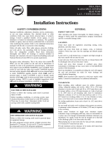
COPELAND/DANFOSS/LG SCROLL
COMPRESSOR
Scroll Gas Flow
Compression in the scroll is
created by the interaction of
an orbiting spiral and a
stationary spiral. Gas enters
an outer opening as one of the
spirals orbits.
The open passage is sealed off
as gas is drawn into the spiral.
By the time the gas arrives at
the center port, discharge
pressure has been reached.
Actually, during operation, all
six gas passages are in various
stages of compression at all
times, resulting in nearly con-
tinuous suction and discharge.
As the spiral continues to orbit,
the gas is compressed into an
increasingly smaller pocket.
1
23
54
A90198
Fig. 17 – Scroll Compressor Refrigerant Flow
The compressors used in these products are specifically designed to
operate with designated refrigerant and cannot be interchanged.
The compressor is an electrical (as well as mechanical) device.
Exercise extreme caution when working near compressors. Power
should be shut off, if possible, for most troubleshooting techniques.
Refrigerants present additional safety hazards.
PERSONAL INJURY HAZARD
Failure to follow this caution may result in personal injury.
Wear safety glasses, protective clothing, and gloves when
handling refrigerant.
CAUTION
!

15
The scroll compressor pumps refrigerant through the system by the
interaction of a stationary and an orbiting scroll. (See Fig. 17.) The
scroll compressor has no dynamic suction or discharge valves, and
it is more tolerant of stresses caused by debris, liquid slugging, and
flooded starts. The compressor is equipped with an internal
pressure relief port. The pressure relief port is a safety device,
designed to protect against extreme high pressure. The relief port
has an operating range between 550 to 625 psig differential
pressure (Copeland) and 550 to 650 psig differential pressure
(Danfoss) for R-- 410A refrigerant. Scrolls have a variety of shut
down solutions, depending on model, to prevent backward rotation
and eliminate the need for cycle protection.
Compressor Failures
Compressor failures are classified in 2 broad failure categories;
mechanical and electrical. Both types are discussed below.
Mechanical Failures
A compressor is a mechanical pump driven by an electric motor
contained in a welded or hermetic shell. In a mechanical failure,
motor or electrical circuit appears normal, but compressor does not
function normally.
ELECTRICAL SHOCK HAZARD
Failure to follow this warning could result in personal
injury or death.
Do not supply power to unit with compressor terminal box
cover removed.
!
WARNING
ELECTRICAL SHOCK HAZARD
Failure to follow this warning could result in personal
injury or death.
Exercise extreme caution when reading compressor currents
when high-- voltage power is on. Correct any of the
problems described below before installing and running a
replacement compressor.
!
WARNING
Locked Rotor
In this type of failure, compressor motor and all starting
components are normal. When compressor attempts to start, it
draws locked rotor current and cycles off on internal protection.
Locked rotor current is measured by applying a clamp--on ammeter
around common (blk) lead of compressor. Current drawn when it
attempts to start is then measured. Locked rotor amp (LRA) value
is stamped on compressor nameplate.
If compressor draws locked rotor amps and all other external
sources of problems have been eliminated, compressor must be
replaced. Because compressor is a sealed unit, it is impossible to
determine exact mechanical failure. However, complete system
should be checked for abnormalities such as incorrect refrigerant
charge, restrictions, insufficient airflow across indoor or outdoor
coil, etc., which could be contributing to the failure.
Runs, Does Not Pump
In this type of failure, compressor motor runs and turns
compressor, but compressor does not pump refrigerant. A
clamp --on ammeter on common leg shows a very low current draw,
much lower than rated load amp (RLA) value stamped on
compressor nameplate. Because no refrigerant is being pumped,
there is no return gas to cool compressor motor. It eventually
overheats and shuts off on its internal protection.
Noisy Compressor
Noise may be caused by a variety of internal and external factors.
Careful attention to the “type” of noise may help identify the
source. The following are some examples of abnormal conditions
that may create objectionable noise:
1. A gurgling sound may indicate a liquid refrigerant
floodback during operation. This could be confirmed if
there is no compressor
superheat. A compressor superheat
of “0” degrees would indicate liquid refrigerant returning to
the compressor. Most common reasons for floodback are:
loss of evaporator blower, dirty coils, and improper airflow.
2. A rattling noise may indicate loose hardware. Inspect all
unit hardware including the compressor grommets.
3. An internal “thunking”, “thumping”, “grinding” or
“rattling” noise could indicate compressor internal failures
and may be verified by comparing the compressor
amperage to what the compressor should be drawing
according to a manufacturer’s performance data.
4. A whistling or squealing noise during operation may
indicate a partial blockage of the refrigerant charge.
5. A whistle on shut down could indicate a partial leak path as
refrigerant is equalizing from high to low side. On
occasion, an in--line discharge check valve has prevented
this sound.
6. If a compressor hums but won’t start it could indicate either
a voltage or amperage issue. Verify adequate voltage and
operational start components if installed. If it is drawing
excessive amperage and voltage doesn’t appear to be the
problem it may be assumed a locked condition. Ensure
refrigerant has had ample time to equalize and boil out of
the compressor before condemning.
7. When a heat pump switches into and out of defrost, a
”swooshing” noise is expected due to the rapid pressure
change within the system. Check that the defrost thermostat
or thermistor is operating properly. Insulating the defrost
sensing device may also help.
Electrical Failures
The compressor mechanical pump is driven by an electric motor
within its hermetic shell. In electrical failures, compressor does not
run although external electrical and mechanical systems appear
normal. Compressor must be checked electrically for abnormalities.
Before troubleshooting compressor motor, review this description
of compressor motor terminal identification.
Single--Phase Motors
To identify terminals C, S, and R:
1. Turn off all unit power.
2. Discharge run and start capacitors to prevent shock.
3. Remove all wires from motor terminals.
4. Read resistance between all pairs of terminals using an
ohmmeter on 0--10 ohm scale.
5. Determine 2 terminals that provide greatest resistance
reading.
Through elimination, remaining terminal must be common (C).
Greatest resistance between common (C) and another terminal
indicates the start winding because it has more turns. This terminal
is the start (S). The remaining terminal will be run winding (R).
NOTE: If compressor is hot, allow time to cool and internal line
break to reset. There is an internal line break protector which must
be closed.
All compressors are equipped with internal motor protection. If
motor becomes hot for any reason, protector opens. Compressor
should always be allowed to cool and protector to close before

16
troubleshooting. Always turn off all power to unit and disconnect
leads at compressor terminals before taking readings.
Most common motor failures are due to either an open, grounded,
or short circuit. When a compressor fails to start or run, 3 tests can
help determine the problem. First, all possible external causes
should be eliminated, such as overloads, improper voltage,
pressure equalization, defective capacitor(s), relays, wiring, etc.
Compressor has internal line break overload, so be certain it is
closed.
Open Circuit
UNIT PERSONAL INJURY HAZARD
Failure to follow this warning could result in personal
injury.
Use caution when working near compressor terminals.
Damaged terminals have the potential to cause personal
injury.
Never put face or body directly in line with terminals.
!
WARNING
To determine if any winding has a break in the internal wires and
current is unable to pass through, follow these steps:
1. Be sure all power is off.
2. Discharge all capacitors.
3. Remove wires from terminals C, S, and R.
4. Check resistance from C--R, C--S, and R--S using an
ohmmeter on 0--1000 ohm scale.
Because winding resistances are usually less than 10 ohms, each
reading appears to be approximately 0 ohm. If resistance remains at
1000 ohms, an open or break exists and compressor should be
replaced.
UNIT DAMAGE HAZARD
Failure to follow this caution may result in equipment
damage or improper operation.
Be sure internal line break overload is not temporarily open.
CAUTION
!
RECIPROCATING COMPRESSOR
The compressor is the heart of the refrigeration system. It pumps
refrigerant through the system. If it malfunctions, system capacity
and efficiency could be negatively affected.
FIRE/EXPLOSION HAZARD
Failure to follow this warning could result in personal
injury or death and/or property damage.
Wear safety glasses and gloves when handling refrigerants.
Keep torches and other ignition sources away from
refrigerants and oils.
!
WARNING
The compressor is an electrical (as well as mechanical) device.
Exercise extreme caution when working near compressors. Power
should be shut off, if possible, for most troubleshooting techniques.
Refrigerants in system present other safety hazards. Always wear
safety glasses and gloves when handling refrigerants.
Compressor Failures
Compressor failures are classified in 2 broad failure categories:
mechanical and electrical. Both types are discussed below.
Mechanical Failures
A compressor is a mechanical pump driven by an electric motor
contained in a welded or hermetic shell. In a mechanical failure,
motor or electrical circuit appears normal, but compressor does not
function normally.
ELECTRICAL SHOCK HAZARD
Failure to follow this warning could result in personal
injury or death.
Before installing, modifying, or servicing system, main
electrical disconnect switch must be in the OFF position.
There may be more than 1 disconnect switch. Lock out and
tag switch with a suitable warning label.
!
WARNING
Locked Rotor
In this type of failure, compressor motor and all starting
components are normal. When compressor attempts to start, it
draws locked rotor current and cycles off on the internal protection.
Locked rotor current is measured by applying a clamp--on ammeter
around common (blk) lead of the compressor on a single-- phase
compressor. Current drawn when it attempts to start is then
measured. LRA (locked rotor amp) value is stamped on
compressor nameplate.
If compressor draws locked rotor amps and all other external
sources of problems have been eliminated, compressor must be
replaced. Because compressor is a sealed unit, it is impossible to
determine exact mechanical failure. However, complete system
should be checked for abnormalities such as incorrect refrigerant
charge, restrictions, insufficient airflow across indoor or outdoor
coil, etc., which could be contributing to the failure.
Runs, Does Not Pump
In this type of failure, compressor motor runs and turns
compressor, but compressor does not pump the refrigerant. A
clamp --on ammeter on common leg of a single--phase compressor,
shows a very low current draw, much lower than RLA (rated load
amps) value stamped on compressor nameplate. Because no
refrigerant is being pumped, there is no return gas to cool
compressor motor. It eventually overheats and shuts off on its
internal protection.

17
POWER OFF!
OHMMETER
0-10Ω SCALE
5.2Ω
0.6Ω
5.8Ω
DEDUCTION:
(EXAMPLE)
TO DETERMINE INTERNAL CONNECTIONS OF SINGLE-
PHASE MOTORS (C,S,R) EXCEPT SHADED-POLE
?
?
?
1
2
2
3
1
3
12
32
1 3 (GREATEST RESISTANCE)
5.8Ω (OHM)
(SMALLEST RESISTANCE)
0.6Ω
(REMAINING RESISTANCE)
5.2Ω
2
2
3
1
IS COMMON (C)
BY ELIMINATION
IS COMMON,
THEREFORE, IS
START WINDING (S)
RUN WINDING (R)
START WINDING (S)
IS RUN WINDING (R)
A88344
Fig. 18 – Identifying Compressor Terminals
Runs, Does Not Pump, High -- To--Low Side Leak
In this type of failure, compressor motor runs and turns
compressor, and compressor is pumping. Usually, an internal
problem such as blown head gasket or broken internal discharge
line causes compressor to pump hot discharge gas back into its
own shell rather than through system.
Using pressure gages on high flow service valves shows high
suction and low discharge pressure readings. Motor currents are
lower than normal. Because hot gas is being discharged into shell,
the shell becomes hot. The hot gas causes compressor motor to
cycle off on its internal protection.
Runs and Pumps, Low Capacity
This failure type is difficult to pinpoint because extent of damage
varies. Compressor is a pump with internal valves that enable
compressor to pump properly. The cylinder has a set of suction and
discharge valves. Any of these parts may become damaged or
broken, causing loss in pumping capacity. Severity of damage
determines amount of capacity loss. Use pressure gages to find any
abnormal system pressures if system charge and other conditions
are normal.
An owner may complain that a unit is not handling the building’s
heating or cooling load. The compressor current draw may be
abnormally low or high. Although this type of failure does occur,
all other possible causes of capacity loss must be eliminated before
condemning compressor.
Noisy Compressor
Noise may be caused by a variety of internal problems such as
loosened hardware, broken mounting springs, etc. System
problems such as overcharged compressor (especially at start--up)
or too much oil in compressor may also cause excessive noise.
Excess oil in compressor is normally encountered only after a
replacement compressor has been added without purging oil from
previous compressor. As new compressor pumps, excess oil in
system returns and adds to volume already present, causing noise.
Compressor Leaks
UNIT DAMAGE AND/OR PERSONAL INJURY
HAZARD
Failure to follow this caution may result in personal injury
and/or unit component damage.
High flow service valves are equipped with Schrader
valves. Wear safety glasses and gloves when handling
refrigerant.
!
CAUTION
Sometimes a leak is detected at weld seam around girth of
compressor or a fitting that joins compressor shell. Many of these
leaks can be repaired and the compressor saved if correct procedure
is followed.
1. Turn off all power to unit.
2. Remove and recover all refrigerant from system so that gage
pressures are 0 psig.
3. Clean area around leak to bare metal.
4. Apply flux and repair joint with silver solder. Do not use
low temperature solder such as 50--50.
5. Clean off excess flux, check for leaks, and apply paint over
repaired area to prevent corrosion.
Do not use this method to repair a compressor leak due to severe
corrosion. Never attempt to repair a compressor leaking at electric
terminals. This type of failure requires compressor replacement.
Electrical Failures
The compressor mechanical pump is driven by an electric motor
within its hermetic shell. In electrical failures, compressor does not
run although external electrical and mechanical systems appear
normal. Compressor must be checked electrically for abnormalities.
Before troubleshooting compressor motor, review this description
of compressor motor terminal identification.
Single--Phase
Motors
To identify terminals C, S, and R:
1. Turn off all unit power.
2. Short the run and start capacitors to prevent shock.
3. Remove all wires from motor terminals.
4. Read resistance between all pairs of terminals using an
ohmmeter on 0--10 ohm scale.
5. Determine 2 terminals that provide greatest resistance
reading.
Through elimination, remaining terminal must be common
(C). Greatest resistance between common (C) and another
terminal indicates start winding because it has more turns.
This terminal is start (S). Remaining terminal will be run
winding (R). (See Fig. 18.)
NOTE: If compressor is hot, allow time to cool and internal line
break to reset. There is an internal line break protector which must
be closed.
Open
Circuit
To determine if any winding has a break in the internal wires and
current is unable to pass through:
1. Be sure all power is off.
2. Discharge all capacitors.
3. Remove wires from terminals C, S and R.
4. Check resistance from C--R, C--S and R--S using an
ohmmeter on 0--1000 ohm scale.
Because winding resistances are usually less than 10 ohms,

18
each reading appears to be approximately 0 ohm. If
resistance remains at 1000 ohms, an open or break exists
and compressor should be replaced. Be sure internal line
break overload is not temporarily open.
Ground
Circuit
To determine if a wire has broken or come in direct contact with
shell, causing a direct short to ground:
1. Be sure all power is off.
2. Discharge all capacitors.
3. Remove wires from terminals C, S, and R.
4. On hermetic compressors, allow crankcase heaters to remain
on for several hours before checking motor to ensure
windings are not saturated with refrigerant.
5. Use an ohmmeter on R X 10,000 ohm scale. A
megohmmeter may be used in place of ohmmeter. Follow
manufacturer’s instructions.
6. Place 1 meter probe on ground or on compressor shell.
Make a good metal--to-- metal contact. Place other probe on
terminals C, S, and R in sequence.
7. Note meter scale.
8. If reading of zero or low resistance is obtained, motor is
grounded. Replace compressor.
A compressor of 1 ton capacity or less is probably grounded if
resistance is below 1 million ohms. On larger sized single--phase
compressors, resistance to ground should not be less than 1000
ohms per volt of operating voltage.
Example:
230 volts X 1000 ohms/volt = 230,000 ohms minimum.
SHORT CIRCUIT
To determine if any wires within windings have broken through
their insulation and made contact with other wires, thereby shorting
all or part of the winding(s), be sure the following conditions are
met:
1. Correct motor winding resistances must be known before
testing, either from previous readings or from
manufacturer’ s specifications.
2. Temperature of windings must be as specified, usually
about 70_F (21.1ºC) .
3. Resistance measuring instrument must have an accuracy
within ± 5--10 percent. This requires an accurate ohmmeter
such as a Wheatstone bridge or null balance--type
instrument.
4. Motor must be dry or free from direct contact with liquid
refrigerant.
Make This Critical Test
(Not advisable unless above conditions are met.)
1. Be sure all power is off.
2. Discharge all capacitors.
3. Remove wires from terminals C, S, and R.
4. Place instrument probes together and determine probe and
lead wire resistance.
5. Check resistance readings from C--R, C--S, and R--S.
6. Subtract instrument probe and lead resistance from each
reading.
If any reading is within ±20 percent of known resistance, motor
is probably normal. Usually a considerable difference in reading is
noted if a turn --to --turn short is present.
System Clean-- Up After Burnout
Turn off all power to unit before proceeding. Wear safety glasses
and gloves when handling refrigerants. Acids formed as a result of
motor burnout can cause burns.
NOTE: To analyze level of suspected contamination from
compressor burnout, use Total Testt. See your distributor/branch.
Some compressor electrical failures can cause motor to overheat.
When this occurs, byproducts, which include sludge, carbon, and
acids, contaminate system. If burnout is severe enough, system
must be cleaned before replacement compressor is installed. The 2
types of motor burnout are classified as mild or severe.
In mild burnout, there is little or no detectable odor. Compressor
oil is clear or slightly discolored. An acid test of compressor oil
will be negative. This type of failure is treated the same as
mechanical failure. Liquid line strainer should be removed and
liquid line filter drier installed.
In a severe burnout, there is a strong, pungent, rotten egg odor.
Compressor oil is very dark. Evidence of burning may be present
in tubing connected to compressor . An acid test of compressor oil
will be positive. Complete system must be reverse flushed with
refrigerant. Metering device must be cleaned or replaced. In a heat
pump, accumulator and reversing valve are replaced. These
components are also removed and bypassed during reverse
flushing procedure. Remove and discard liquid line strainer. After
system is reassembled, install liquid and suction line filter driers.
Run system for 2 hrs. Discard both driers and install new liquid
line drier only.
Compressor Removal and Replacement
Once it is determined that compressor has failed and the reason
established, compressor must be replaced.
PERSONAL INJURY HAZARD
Failure to follow this caution may result in personal injury.
Wear safety glasses, protective clothing, and gloves when
handling refrigerant and observe the following:
The high flow service valve is equipped with Schrader
valves.
!
CAUTION
PERSONAL INJURY AND ENVIRONMENTAL
HAZARD
Failure to follow this warning could result in personal
injury or death. Relieve pressure and recover all refrigerant
before system repair or final unit disposal. Use all service
ports and open all flow --control devices, including solenoid
valves. Federal regulations require that you do not vent
refrigerant to the atmosphere. Recover during system repair
or final unit disposal.
!
WARNING
1. Shut off all power to unit.
2. Remove and recover all refrigerant from system until
pressure gages read zero psig. Use all service ports.
3. Disconnect electrical plug from compressor. Disconnect or
remove crankcase heater (if equipped) and remove
compressor holddown nuts and washers.
4. Cut compressor from system with tubing cutters. Do not use
brazing torch for compressor removal. Oil vapor may ignite
when compressor is disconnected.
5. Scratch matching marks on stubs in old compressor. Make
corresponding marks on replacement compressor .
6. Use torch to remove stubs from old compressor and to
reinstall them in replacement compressor.
7. Use copper couplings to tie compressor back into system.
8. Evacuate system, recharge, and check for normal system
operation.

19
9. Compressors have copper plated steel suction ports. Excess
heat during brazing will burn off copper plating. See
Brazing section for additional information.
Outdoor Fan Adjustment
UNIT OPERATION HAZARD
Failure to follow this caution may result in damage to unit
components.
Keep the condenser fan free from all obstructions to ensure
proper cooling operation. Never place articles on top of
unit.
CAUTION
!
1. Shut off unit power supply and install lockout tag.
2. Remove outdoor--fan assembly (grille, motor, motor cover,
and fan) by removing screws and flipping assembly onto
unit top cover.
3. Inspect the fan blades for cracks or bends.
4. If fan needs to be removed, loosen the setscrew and slide the
fan off the motor shaft.
5. When replacing fan blade, position blade as shown in Fig.
19. Tighten setscrews.
Fan Motor
The fan motor rotates the fan blade that draws air through the
outdoor coil to exchange heat between the refrigerant and the air.
Motors are totally enclosed to increase reliability. This eliminates
the need for a rain shield. For the correct position of fan blade
assembly, the fan hub should be flush with the motor shaft.
Replacement motors and blades may vary slightly.
A
024 13/16 (20.6)
030 13/16 (20.6)
036 0
042 0
048 0
060 3/16 (4.8)
FAN
HUB
MOTOR
SHAFT
AC UNIT
SIZE
A
in. (mm)
13 & 14 SEER
A14540
A
FAN
HUB
MOTOR
SHAFT
13 SEER
HP SIZE
024
030
036
042
048
060
A
in. (mm)
13/16 (20.6)
1/2 (12.7)
13/16 (20.6)
0
0
0
14 SEER
HP SIZE
024
030
036
042
048
A
in. (mm)
13/16 (20.6)
13/16 (20.6)
0
0
1/2 (12.7)
060
1/2 (12.7)
A150078
Fig. 19 – Outdoor Fan Adjustment
ELECTRICAL SHOCK HAZARD
Failure to follow this warning could result in personal
injury or death.
Turn off all power before servicing or replacing fan motor.
Be sure unit main power switch is turned off. Lock out and
tag with suitable warning label.
!
WARNING
The bearings are permanently lubricated, therefore, no oil ports are
provided.
For suspected electrical failures, check for loose or faulty electrical
connections, or defective fan motor capacitor. Fan motor is
equipped with thermal overload device in motor windings which
may open under adverse operating conditions. Allow time for
motor to cool so device can reset. Further checking of motor can be
done with an ohmmeter. Set scale on R X 1 position, and check for
continuity between 3 leads. Replace motors that show an open
circuit in any of the windings. Place 1 lead of ohmmeter on each
motor lead. At same time, place other ohmmeter lead on motor case
(ground). Replace any motor that shows resistance to ground,
arcing, burning, or overheating.
Compressor Plug
The compressor electrical plug provides a quick-- tight connection
to compressor terminals. The plug completely covers the
compressor terminals and the mating female terminals are
completely encapsulated in plug. Therefore, terminals are isolated
from any moisture so corrosion and resultant pitted or discolored
terminals are reduced. The plug is oriented to relief slot in terminal
box so cover cannot be secured if wires are not positioned in slot,
assuring correct electrical connection at the compressor. The plug
can be removed by simultaneously pulling while “rocking“ plug.
However, these plugs can be used only on specific compressors.
The configuration around the fusite terminals is outlined on the
terminal covers. The slot through which wires of plug are routed is
oriented on the bottom and slightly to the left. The correct plug can
be connected easily to compressor terminals and plug wires can
easily be routed through slot terminal cover.
It is strongly recommended to replace the compressor plug should
a compressor fail due to a suspected electrical failure. At a
minimum, inspect plug for proper connection and good condition
on any compressor replacement.
Low--Voltage Terminals
The low--voltage terminal designations, and their description and
function, are used on all Small Packaged Products (SPP)
condensers.
W—Energizes first--stage supplemental heat.
R—Energizes 24--v power from transformer.
Y—Energizes contactor for first--stage cooling or first--stage
heating for heat pumps.
O—Energizes reversing valve on heat pumps.
C—Common side of transformer .
G—Indoor Fan
Ground Circuit
To determine if a wire has broken or come in direct contact with
shell, causing a direct short to ground, follow these steps:
1. Recover all refrigerant charge.
2. Using an ohmmeter on R X 10,000 ohm scale or
megohmmeter (follow manufacturer’s instructions).
3. Be sure all power is off.
4. Discharge all capacitors.
5. Remove compressor plug.

20
6. Place one meter probe on ground or on compressor shell.
Make a good metal--to-- metal contact. Place other probe on
terminals C, S, and R in sequence.
7. Note meter scale.
8. If reading of 0 or low resistance is obtained, motor is
grounded. Replace compressor.
Compressor resistance to ground should not be less than 1000
ohms per volt of operating voltage.
Example:
230 volts X 1000 ohms/volt = 230,000 ohms minimum.
Short Circuit
To determine if any wires within windings have broken through
their insulation and made contact with other wires, thereby shorting
all or part of the winding(s), be sure the following conditions are
met.
1. Correct motor winding resistances must be known before
testing, either from previous readings or from
manufacturer’ s specifications.
2. Temperature of windings must be as specified, usually
about 70_F (21ºC) .
3. Resistance measuring instrument must have an accuracy
within 5--10 percent. This requires an accurate ohmmeter
such as a Wheatstone bridge or null balance--type
instrument.
4. Motor must be dry or free from direct contact with liquid
refrigerant.
Make This Critical Test
(Not advisable unless above conditions are met)
1. Be sure all power is off.
2. Recover all refrigerant charge.
3. Discharge all capacitors.
4. Remove wires from terminals C, S, and R.
5. Place instrument probes together and determine probe and
lead wire resistance.
6. Check resistance readings from C--R, C--S, and R--S.
7. Subtract instrument probe and lead resistance from each
reading.
If any reading is within 20 percent of known resistance, motor is
probably normal. Usually a considerable difference in reading is
noted if a turn --to --turn short is present.
REFRIGERATION SYSTEM
Refrigerant
UNIT OPERATION AND SAFETY HAZARD
Failure to follow this warning could result in personal
injury or equipment damage.
R--410A refrigerant which has higher pressures than R --22
and other refrigerants. No other refrigerant may be used in
this system. Gauge set, hoses, and recovery system must be
designed to handle R--410A. If you are unsure consult the
equipment manufacturer.
!
WARNING
In an air conditioning and heat pump system, refrigerant transfers
heat from one replace to another. The condenser is the outdoor coil
in the cooling mode and the evaporator is the indoor coil.
In a heat pump, the condenser is the indoor coil in the heating
mode and the evaporator is the outdoor coil.
In the typical air conditioning mode, compressed hot gas leaves the
compressor and enters the condensing coil. As gas passes through
the condenser coil, it rejects heat and condenses into liquid. The
liquid leaves condensing unit through liquid line and enters
metering device at evaporator coil. As it passes through metering
device, it becomes a gas--liquid mixture. As it passes through
indoor coil, it absorbs heat and the refrigerant moves to the
compressor and is again compressed to hot gas, and cycle repeats.
Compressor Oil
UNIT DAMAGE HAZARD
Failure to follow this caution may result in equipment
damage or improper operation.
The compressor in a R-- 410A system uses a polyolester
(POE) or polyvinyl ether (PVE) oil. This oil is extremely
hygroscopic, meaning it absorbs water readily. POE/PVE
oils can absorb 15 times as much water as other oils
designed for HCFC and CFC refrigerants. Take all
necessary precautions to avoid exposure of the oil to the
atmosphere. (See Table 3.)
CAUTION
!
Brazing
This section on brazing is not intended to teach a technician how to
braze. There are books and classes which teach and refine brazing
techniques. The basic points below are listed only as a reminder.
Definition: The joining and sealing of metals using a nonferrous
metal having a melting point over 800_F/426.6_C.
Flux: A cleaning solution applied to tubing or wire before it is
brazed. Flux improves the strength of the brazed connection.
When brazing is required in the refrigeration system, certain basics
should be remembered. The following are a few of the basic rules.
1. Clean joints make the best joints. To clean:
Remove all oxidation from surfaces to a shiny
finish before brazing.
Remove all flux residue with brush and water while
material is still hot.
2. Silver brazing alloy is used on copper-- to --brass,
copper-- to --steel, or copper--to --copper. Flux is required
when using silver brazing alloy. Do not use low temperature
solder .
3. Fluxes should be used carefully. Avoid excessive
application and do not allow fluxes to enter into the system.
4. Brazing temperature of copper is proper when it is heated to
a minimum temperature of 800_F (426.6_C) and it is a dull
red color in appearance.
Reversing Valve
In heat pumps, changeover between heating and cooling modes is
accomplished with a valve that reverses flow of refrigerant in
system. This reversing valve device is easy to troubleshoot and
replace. The reversing valve solenoid can be checked with power
off with an ohmmeter. Check for continuity and shorting to
ground. With control circuit (24v) power on, check for correct
voltage at solenoid coil. Check for overheated solenoid.
With unit operating, other items can be checked, such as frost or
condensate water on refrigerant tubes.
The sound made by a reversing valve as it begins or ends defrost is
a “whooshing” sound, as the valve reverses and pressures in system
equalize. An experienced service technician detects this sound and
uses it as a valuable troubleshooting tool.
Using a remote measuring device, check inlet and outlet line
temperatures. DO NOT touch lines. If reversing valve is operating
normally, inlet and outlet temperatures on appropriate lines should
be close to each other. Any difference would be due to heat loss or
gain across valve body. Temperatures are best checked with a
remote reading electronic--type thermometer with multiple probes.
/