
MTL5500 range
Isolating interface units
May 2017
INM 5500 Rev 10
Instruction manual
MTL intrinsic safety solutions

INM 5500 Rev 10
ii
DECLARATION OF CONFORMITY
A printed version of the Declaration of Conformity has been provided separately within
the original shipment of goods. However, you can find a copy of the latest version at:
http://www.mtl-inst.com/certificates

INM 5500 Rev 10
iii
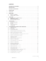
CONTENTS
DECLARATION OF CONFORMITY ......................................................II
IMPORTANT NOTE ................................................................. V
ATEX SAFETY INSTRUCTIONS .......................................................VI
1 INTRODUCTION ....................................................................1
2 DESCRIPTION ......................................................................1
3 INSTALLATION .....................................................................2
3.1 Modules – pre-installation .................................................................3
3.2 Installing columns of isolators .............................................................4
4 ACCESSORIES .....................................................................6
4.1 MTL5500 power bus - Installation and use ...................................................6
4.2 MPA5500 AC power adaptor ...............................................................7
4.3 Earth rail and tagging accessories ..........................................................8
5 DX ENCLOSURES ..................................................................12
5.1 Environmental conditions ................................................................12
5.2 Mounting ..............................................................................16
5.3 Accessories in enclosures ...............................................................17
5.4 IS warning label ........................................................................17
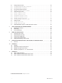
6 UNIT DESCRIPTIONS, SETTING-UP AND CONNECTIONS .................................18
6.1 Digital Input modules ...................................................................19
6.1.1 Phase reversal ..........................................................................19
6.1.2 Line-Fault Detection (LFD) ................................................................19
6.1.3 MTL5501-SR - Fail-safe Switch/Proximity detector interface .......................................20
6.1.4 MTL5510 & MTL5510B - Switch/Proximity detector interface ......................................21
6.1.5 MTL5511 - Switch/Proximity detector interface .................................................25
6.1.6 MTL5513 - Switch/Proximity detector interface .................................................26
6.1.7 MTL5514/ MTL5514D/MTL5514-T - Switch/Proximity detector interface .............................27
6.1.8 MTL5516C - Switch/Proximity detector interface ................................................28
6.1.9 MTL5517 - Switch/Proximity detector interface .................................................29
6.2 Digital Output modules ..................................................................30
6.2.1 MTL5521/MTL5521-T - Solenoid Alarm driver ..................................................30
6.2.2 MTL5522 - Solenoid Alarm driver ............................................................31
6.2.3 MTL5523 - Solenoid Alarm driver ............................................................32
6.2.4 MTL5523V/MTL5523VL - Solenoid Alarm driver .................................................33
6.2.5 MTL5524 - Solenoid Alarm driver ............................................................34
6.2.6 MTL5525 - Solenoid Alarm driver ............................................................35
6.2.7 MTL5526 - Switch Operated Relay ...........................................................36
6.3 Pulse and Vibration modules. . . . . . . . . . . . . . . . . . . . . . . . . . . . . . . . . . . . . . . . . . . . . . . . . . . . . . . . . . . . . .37
6.3.1 MTL5531 - Vibration Transducer Interface ......................................................37
6.3.2 MTL5532 - Pulse Isolator ..................................................................38
6.3.3 MTL5533 - Vibration Transducer Interface ......................................................40
6.4 Analogue Input modules .................................................................41
6.4.1 MTL5541/MTL5541S/MTL5541S-T - Repeater Power Supply ......................................41
6.4.2 MTL5541A/MTL5541AS - Repeater Power Supply ...............................................42
6.4.3 MTL5544/MTL5544S - Repeater Power Supply .................................................43
6.4.4 MTL5544A/MTL5544AS - Current Repeater ....................................................44
6.4.5 MTL5544D - Repeater Power Supply .........................................................45
(continued on next page)

INM 5500 Rev 10
iv
6.5 Analogue Output modules ...............................................................46
6.5.1 MTL5546/MTL5546Y/MTL5546Y-T - Isolating Driver .............................................46
6.5.2 MTL5549/ MTL5549Y - Isolating Driver .......................................................47
6.6 Fire and Smoke Interface modules .........................................................48
6.6.1 MTL5561 - Fire and Smoke Detector Interface .................................................48
6.7 Temperature Input module ...............................................................49
6.7.1 MTL5573 - Temperature Converter ...........................................................50
6.7.2 MTL5575 - Temperature Converter ...........................................................51
6.7.3 MTL5576-RTD - Temperature Converter .......................................................52
6.7.4 MTL5576-THC - Temperature Converter .......................................................53
6.7.5 MTL5581 - mV/Thermocouple Isolator ........................................................54
6.7.6 MTL5582/MTL5582B - mV/Resistance Isolator .................................................55
6.8 General modules .......................................................................56
6.8.1 MTL5599 - Dummy Isolator ................................................................56
6.8.2 MTL5991 - 24V dc power supply ............................................................57
6.9 PCS45/PCL45USB configurator for MTL temperature converters ................................58
7 FAULT FINDING AND ROUTINE MAINTENANCE ........................................59
7.1 Maintenance precautions ................................................................59
7.2 Fault finding ...........................................................................59
7.3 Routine maintenance ....................................................................59
8 BENCH TESTING MODULES .........................................................60
8.1 Digital Input (DI) modules ................................................................60
8.2 Digital Output (DO) modules. . . . . . . . . . . . . . . . . . . . . . . . . . . . . . . . . . . . . . . . . . . . . . . . . . . . . . . . . . . . . .61
8.3 Analogue Input (AI) Modules .............................................................62
8.4 Analogue Output (AO) Modules ...........................................................65
8.5 Testing the functioning of other modules ...................................................65
9 APPLICATIONS INVOLVING ZONE 2 AND/OR ZONE 22 HAZARDOUS AREAS ................66
9.1 Enclosure ..............................................................................66
10 APPENDIX 1 ......................................................................67
10.1 MTL5000 ..............................................................................67
10.2 MTL5018AC - Switch/proximity detector ....................................................68
10.3 MTL5051 serial data comms isolator .......................................................70
10.4 MTL5314 trip amplifier for 2– or 3– wire transmitters .........................................73
11 APPENDIX 2 ......................................................................76
11.1 Table A - Safety descriptions ..............................................................76
11.2 Table B - Maximum cable parameters - IIC gas group . . . . . . . . . . . . . . . . . . . . . . . . . . . . . . . . . . . . . . . . . 76
11.3 Table C - Maximum cable parameters - IIB gas group . . . . . . . . . . . . . . . . . . . . . . . . . . . . . . . . . . . . . . . . . 76
© 2017 Eaton Electric Limited. All rights reserved.

INM 5500 Rev 10
v
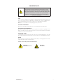
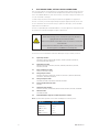
IMPORTANT NOTE
WARNING
This manual has content describing the use and installation of safety
equipment. This equipment must be installed, operated and maintained
only by trained competent personnel and in accordance with all appropriate
international, national and local standard codes of practice and site
regulations for intrinsically safe apparatus and in accordance with the
instructions contained here.
ATEX
If the country of installation is governed by the Essential Health and Safety Requirements
(Annex II) of the EU Directive 2014/34/EU [the ATEX Directive - safety of apparatus] then
consult the ATEX safety instructions for safe use in this manual before installation.
Note: Refer to the website for multiple language safety instructions.
ELECTRICAL PARAMETERS
Refer to the certification documentation for the electrical rating of these products.
CERTIFICATION DOCUMENTATION
Our website http://www.mtl-inst.com contains product documentation regarding intrinsic
safety certification for many locations around the world. Consult this data for information
relevant to your local certifying authority.
FUNCTIONAL SAFETY
If the MTL5500 range of products are to be used in functional safety applications check that
each module has been assessed for that service and refer to the Safety Manual for details.
REPAIR
MTL5500 range of products MUST NOT be repaired. Faulty or damaged products must be
replaced with an equivalent certified product.
Symbols used on the product and in this manual
CAUTION -
Read the instructions
CAUTION -
Hot surface

INM 5500 Rev 10
vi
ATEX SAFETY INSTRUCTIONS
The following information is in accordance with the Essential Health and Safety Requirements
(Annex II) of the EU Directive 2014/34/EU [the ATEX Directive - safety of apparatus] and is
provided for those locations where the ATEX Directive is applicable.
General
a) This equipment must only be installed, operated and maintained by competent personnel.
Such personnel shall have undergone training, which included instruction on the various
types of protection and installation practices, the relevant rules and regulations, and on the
general principles of area classification. Appropriate refresher training shall be given on a
regular basis. [See clause 4.2 of EN 60079-17].
b) This equipment has been designed to provide protection against all the relevant additional
hazards referred to in Annex II of the directive, such as those in clause 1.2.7.
c) This equipment has been designed to meet the requirements of EN 60079-15.
Installation
a) The installation must comply with the appropriate European, national and local regulations,
which may include reference to the IEC code of practice IEC 60079-14. In addition, particular
industries or end users may have specific requirements relating to the safety of their
installations and these requirements should also be met. For the majority of installations the
Directive 1999/92/EC [the ATEX Directive - safety of installations] is also applicable.
b) This apparatus is an associated electrical apparatus and is normally mounted in a non-
hazardous [safe] area. Specific apparatus described as Category 3 compliant may be
installed in a Zone 2 location providing that the relevant installation conditions are met. When
mounted in a Zone 2 location the apparatus must be provided with an enclosure, which
offers an additional degree of protection appropriate to the area classification.
c) Unless already protected by design, this equipment must be protected by a suitable
enclosure against:
i) mechanical and thermal stresses in excess of those noted in the certification
documentation and the product
specification
ii) aggressive substances, excessive dust, moisture and other contaminants.
Read also the Special Conditions for Safe Use (below) for any additional or more specific
information.
Special Conditions of Safe Use for Zone 2 applications
a) When used in Zone 2, the equipment must be installed in an enclosure or an
environment that provides a degree of protection of at least IP54 and meets
the relevant material and environmental requirements of EN 60079-0:2012
and EN 60079-15:2010.
b) The equipment must not be inserted or removed unless either:
i) the area in which the equipment is installed is known to be non-hazardous
or
ii) the circuit to which it is connected has been de-energised.
c) The 24V supply for this equipment must be derived from a regulated power
supply complying with the requirements of European Community Directives.
d) For 5511, 5514, 5514D, 5516C, 5517, 5526 & 5532 only: Relay contacts may
switch up to 35V, 2A and 100VA.
For 5575: Relay contacts may switch up to 35V, 250mA.
e) For 5573 Maximum Input/Output parameters – see certificate

INM 5500 Rev 10
vii
Inspection and maintenance
a) Inspection and maintenance should be carried out in accordance with European, national
and local regulations which may refer to the IEC standard IEC 60079-17. In addition specific
industries or end users may have specific requirements which should also be met.
b) Access to the internal circuitry must not be made during operation.
Repair
a) This product cannot be repaired by the user and must be replaced with an equivalent certified
product.
Marking
Each device is marked in compliance with the Directive and CE marked with the Notified Body
Identification Number.
This information applies to MTL5500 products manufactured during or after the year 2015.

INM 5500 Rev 10
viii
This page is left intentionally blank

INM 5500 Rev 10
1
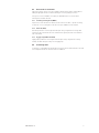
1 INTRODUCTION
This instruction manual describes the procedures for installing, connecting, checking and
maintaining MTL5500 range of isolating interfaces and accessories. The MTL5500 products provide
a DIN-rail mounted, intrinsically safe interface to hazardous areas of a process plant.
The individual sections of this manual cover the following topics
•
Section 2 describes the range
• Section 3 specifies precautions both before and during installation
• Section 4 describes mounting accessories and the power adaptor
• Section 5 discusses the DX range of enclosures
• Section 6 provides relevant technical data
• Section 7 outlines fault-finding and maintenance procedures
• Section 8 describes bench test procedure
• Section 9 provides hazardous-area application information
• Section 10 provides MTL5000 products information
• Section 11 provides safety parameter information
2 DESCRIPTION
MTL5500
range of
isolators provide intrinsically safe (IS) communication and signal conditioning
for a wide range of hazardous-area devices. Total AC and DC isolation exists between input,
output and power supply on separately powered units, and between input and output on
loop-powered units. No IS earth is required. DIN-rail mounting and plug-in signal and power
connectors simplify installation and maintenance. Units are powered from a 20 to 35V DC
supply, or, in some cases, from the signal itself.
Our latest generation of IS interfaces utilises an innovative “One-Core” technology to ensure
the highest quality and availability while maintaining maximum flexibility at lowest cost.
Incorporating advanced circuit design, a common set of components and innovative isolating
transformer construction, they achieve a significant reduction in power consumption while
increasing channel packing densities. The compact, 16mm wide design reduces weight and
gives exceptionally high packing density. They build on the proven success of the MTL2000,
3000, 4000 and 5000 ranges to bring the benefits of new developments in galvanic isolation
without compromising the reliability of the designs from which they have evolved.
The backplane mounting MTL4500
range
is designed with system vendors in mind for “project-
focussed” applications such as Distributed Control System (DCS), Emergency Shutdown
Systems (ESD) and Fire and Gas monitoring (F&G).
The DIN-rail mounting MTL5500 range meets the needs of the IS interface market for
“application focussed” projects, ranging from single instrument loops, through to fully equipped
cabinets, across all industries where hazardous areas exist.
Both new ranges have been designed for compatibility with earlier models. The MTL4500 range
provides plug-replacements for earlier MTL4000 range of units, while the MTL5500 models
can easily replace MTL5000
range of
units. Each offer the latest in modern technology and
efficiency without compromise.
In addition to their use in IS circuits, specific models within the MTL4500 and MTL5500
ranges have been assessed and approved for use in Functional Safety applications. These
have been verified under the certified Functional Safety Management (FSM) programme
implemented by us.

INM 5500 Rev 10
2
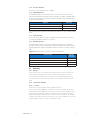
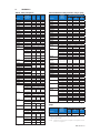
The table below lists the modules in the MTL5500 range. Refer also to the individual MTL5500
range of data sheets.
Digital Input Channels Function
MTL5501-SR 1 fail-safe, solid-state output + LFD alarm
MTL5510 4 switch/prox input, solid-state output
MTL5510B 4 multi-function, switch/prox input, solid-state output
MTL5511 1 switch/prox input, c/o relay output
MTL5513 2 switch/prox input, solid-state output
MTL5514/5514-T 1 switch/prox input, relay + LFD
MTL5514D 1 switch/prox input, dual relay output
MTL5516C 2 switch/prox input, relay + LFD outputs
MTL5517 2 switch/prox input, c/o relay + LFD outputs
Digital Output
MTL5521/5521-T 1 loop-powered solenoid driver
MTL5522 1 loop-powered solenoid driver, IIB
MTL5523 1 solenoid driver with LFD
MTL5523V 1 solenoid driver with LFD + voltage control, IIC
MTL5523VL 1 solenoid driver with LFD + voltage control, IIC
MTL5524 1 switch operated solenoid driver
MTL5525 1 switch operated solenoid driver, low power
MTL5526 2 switch operated relay
Pulse & Vibration Output
MTL5531 1 vibration probe interface
MTL5532 1 pulse isolator, digital or analogue output
MTL5533 2 vibration probe interface
Analogue Input
MTL5541 1 2/3 wire transmitter repeater
MTL5541A 1 transmitter repeater, passive input
MTL5541AS 1 transmitter repeater, passive input, current sink
MTL5541S/5541S-T 1 2/3 wire transmitter repeater, current sink
MTL5544 2 2/3 wire transmitter repeater
MTL5544A 2 transmitter repeater, passive input
MTL5544AS 2 transmitter repeater, passive input, current sink
MTL5544S 2 2/3 wire transmitter repeater, current sink
MTL5544D 1 2/3 wire transmitter repeater, dual output
Analogue Output
MTL5546 1 4-20mA smart isolating driver + LFD
MTL5546Y/5546Y-T 1 4-20mA smart isolating driver + oc LFD
MTL5549 2 4-20mA smart isolating driver + LFD
MTL5549Y 2 4-20mA smart isolating driver + oc LFD
Fire and Smoke
MTL5561 2 loop-powered for fire & smoke detectors
Temperature Input
MTL5573 1
temperature converter, THC or RTD
MTL5575 1 temperature converter, THC or RTD
MTL5576-RTD 2 temperature converter, RTD
MTL5576-THC 2 temperature converter, THC
MTL5581 1 mV/thermocouple isolator for low level signals
MTL5582/5582B 1 mV/resistance isolator to repeat RTD signals
General
MTL5599 1 dummy module

INM 5500 Rev 10
3
3 INSTALLATION
Important
• Make sure that all installation work is carried out in accordance with all relevant local
standards, codes of practice and site regulations.
• When planning the installation of MTL5500
range of
isolators it is essential to make sure
that intrinsically safe and non-intrinsically safe wiring is segregated, and that units are
installed as required by a nationally accepted authority or as described in EN 60079-14, ISA
RP 12.6 or DIN VDE-165.
• External power supply shall contain double isolation from hazardous voltages or that unit
shall be supplied by Limited Power Circuit per UL/IEC 60950 or Limited Energy Circuit per
UL/IEC 61010 or Class ll Power Supply per NEC.
• Environmental conditions: indoor use, altitude (up to 2000m) and humidity less than 95%
non condensing.
• Check that the hazardous-area equipment complies with the descriptive system
document.
• If in doubt, refer to the certificate/catalogue for clarification of any aspects of intrinsic
safety or contact Eaton’s MTL product line or your local representative for assistance.
• Make sure the correct hazardous-area connector (field-wiring plug) is plugged into the
corresponding isolator. It is recommended that the connector is identified by the same tag
number as the matching isolator.
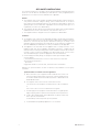
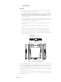
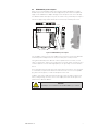
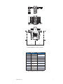
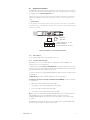
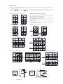
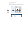
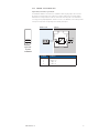
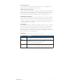
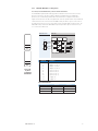
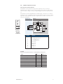
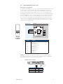
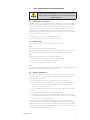
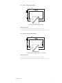
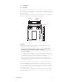
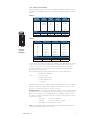
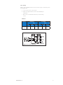
Figure 3.1: Dimensions of MTL5500 package
Mount all MTL5500
range of
isolators on low-profile (7mm) or high-profile (15mm) type
T35 (top-hat) DIN-rail to EN50022, BS5584, DIN46277. This is available from Eaton, in
1 metre lengths (THR2 - DIN rail). Install isolators within the safe area unless they are
enclosed in approved flameproof, pressurised or purged enclosures and ensure that
the local environment is clean and free of dirt and dust. Note the ambient temperature
considerations of section 3.1.4.
It is recommended that, in normal practice, the DIN rail should be earthed/grounded
to ensure the safety of personnel in the event of a.c. mains (line) power being applied
accidentally to the rail.
SAFE
HAZ
104.8
109.8
123.6
118.8
Top of DIN rail
PWR
OPB
OP A
OPD
OPC
FLT
Optional TH5000 tag holder for individual
isolator identification.
Accepts tag label 25 x 12.5 ±0.5mm, 0.2mm thick
15.8 +/– 0.2

INM 5500 Rev 10
4
3.1 Modules – pre-installation
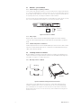
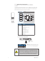
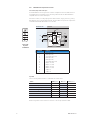
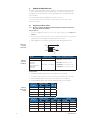
3.1.1 Switch settings for operating conditions
Some modules have operating conditions, such as Line-Fault Detection (LFD), Phase Reversal,
etc., that can be established by the setting of switches on the unit. The subminiature switches
are accessible through an aperture on the side of the module (see Figure 3.2) and can be set in
the required positions with, for example, the blade of a small screwdriver.
The switch setting options are always indicated on the side label of the module, but the user may
also consult the individual module information in Section 6 of this manual for details.
Figure 3.2: Location of switches
3.1.2 Relay outputs
Reactive loads on all units with relays should be adequately suppressed. To achieve maximum
contact life on all mechanical output relays, the load should not be less than 50mW, e.g. 10mA at ≥
5V DC.
3.1.3 Ambient temperature considerations
Ambient temperature limits for unenclosed MTL5500 range of isolators are from –20°C to +60°C
with units close-packed and modules with the -T suffix have an extended temperature rating of
+65°C, unless otherwise specified.
3.2 Installing columns of isolators
On new installations, if isolators are mounted in several rows or columns, mount alternate rows or
columns so that units face in opposite directions. This allows safe- and hazardous-area wiring looms
to be shared.
See Figure 3.1 for isolator dimensions.
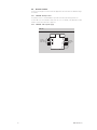
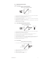
3.2.1 Mounting isolators on DIN rail
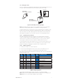
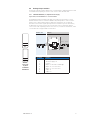
Figure 3.3: DIN rail mounting and removal of isolators
Clip an isolator onto the DIN rail as shown in Figure 3.3, with the blue signal plugs facing
towards the hazardous-area. To remove an isolator from the rail, insert a screwdriver blade
(2.5 - 5.0mm diam.) into the clip as shown. This will release the clip so that the isolator may
be pivoted off the rail - there is no need to lever the clip. Allow a maximum mounting pitch of
16.2mm for each unit.
OFF position
ON position
1 2 3 4
Mounting
Removal

INM 5500 Rev 10
5
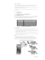
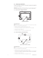
3.2.2 Wiring up isolators
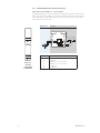
Each unit is supplied with the appropriate number and type of safe- and hazardous-area connectors
(see Figure 3.4), as dictated by the terminals used and the type of power supply.
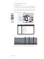
Figure 3.4: Removable power and signal plugs
Note: Earth Leakage Detection requires the use of hazardous area connector type HAZ1-3,
which may need to be ordered separately. See datasheet for ordering information.
Loop-powered devices do not require power connectors. Depending on the installation, it may
be easier to wire up isolators with power and signal plugs either in place or removed. Either
way, allow sufficient free cable to permit plugs to be removed easily for future maintenance
and/or replacement purposes. See Section 6 for instructions on wiring individual modules.
3.2.2.1 Signal and power conductors
Removable signal and power plugs are fitted with screw clamp terminals. Note that the
conductors should be between 14 and 24 AWG (1.6 and 0.5mm diam.) in size. Signal plugs,
located on top of the modules, are mechanically keyed to fit in only one position. They are
coloured grey, for safe-area connections, and blue, for hazardous-area connections.
For externally powered units, a power plug slots into the socket at terminals 13 and 14 on the
safe-area side of each module. The socket is coloured black if the unit is dc powered. Power
plugs are coloured grey, for plugging into the black sockets of dc powered units.
3.2.2.2 Making connections
a) Trim back the insulation of conductors by 12mm.
b) Check the terminal assignments shown in section 6 or on the side label of the unit.
c) Insert conductors according to the terminal assignments and tighten screws.
If the wires are to be fitted with crimp ferrules, the following is a list of those recommended with
required trim lengths for each:
Plug
type
Entry Wire size
(mm
2
)
Metal tube
length (mm)
Tri m
length
Recommended ferrules
Signal Single 0.75 12 14
Weidmuller 902591
Signal Single 1. 0 12 14
Cembre PKC112
Signal Single 1. 0 12 14
Phoenix Contact
AI 1-12 RD (3200674)
Signal Single 1. 5 12 14
Cembre PKE1518†
Signal Single 2.5 12 14
Cembre PKE2518†
Power Twin 2x0.75 10 12
Cembre PKET7510
Power Twin 2x0.75 10 12
AMP (non-preferred) 966144-5
Power Twin 2x1.0 10 12
Phoenix Contact AI-TWIN 2X 1-10 RD
Power Single 0.75 10 12
AMP 966067-0
Power Single 1. 0 10 12
Phoenix Contact AI 1-10 RD
TABLE 3.1: Crimp Ferule Options
† These ferrules with 18mm length metal tubes should be cut to 12mm after crimping
Note: Smaller section wire than that stated can often be successfully used if the crimping is good.
Crimp tool: Phoenix Contact Crimpfox UD6 part number 1204436
Power Plugs
Grey: dc supplies (PWR5000)
Signal Plugs
Grey: safe-area side
Blue: hazardous-area side
12mm
trim
length
with ferrule
see table below

INM 5500 Rev 10
6
3.2.2.3 Finishing
Wire up individual isolators in accordance with wiring schedules. Daisy-chain power supply
connections between individual power plugs or use the power bus (see section 4.1).
Segregate hazardous- and safe-area wiring into separate trunking or looms wherever possible to
avoid errors and maintain a tidy installation.
Use an MTL5599 dummy isolator to provide termination and earthing for unused cores from the
hazardous area.
4 ACCESSORIES
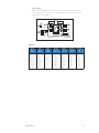
4.1 MTL5500 power bus - Installation and use
4.1.1 MTL5500 range power bus
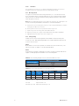
A power bus kit enables power supply terminals (13 and 14) of up to 32 installed MTL5500 range of
units to be linked to a standard 24V power supply. The bus consists of a chain of power plugs and
different lengths are available to suit various numbers of modules as follows.
Number of modules
Kit ID code
(contains grey power plugs for 24V dc supply)
1 to 8 PB-8T
9 to 16 PB-16T
17 to 24 PB-24T
25 to 32 PB-32T
Table 4.1: Power bus kit options
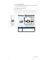
4.1.2 Installation
1. Check to make sure the bus length is correct for the number of modules involved.
2. If the number of modules is less than the maximum number the chain will support, cut off
the surplus power plugs at the tail end of the chain - leaving sufficient cable to attach further
power plugs if it becomes necessary later.
3. Insert power plugs into the power terminals on the safe- area side of each module in sequence.
4. Connect the power supply source to the tail end of the chain (using the insulation displacement
connectors [Scotchloks] provided if required).
Notes:
1. To avoid excessive voltage drop or over-current, DO NOT connect power buses in .
2. Surplus sections can be used (and, if required) connected together provided the cut ends are
safely terminated and/or connected together. Use single ferrules with a crimp tool or insulation
displacement connectors (Scotchloks). Suitable ferrules and connectors are provided with the kits.
Figure 4.1: Power bus wiring, joining and terminating
– +
Optional insulation
displacement
connectors
x2

INM 5500 Rev 10
7
4.2 MPA5500 AC power adaptor
When only one or two MTL5500 modules are required for a particular application, it may be
desirable to power the units from the AC mains supply directly, rather than use a separate DC
supply unit. The MPA5500 is an adaptor that plugs into the DC power socket on the side edge
of an MTL5500 module and clips securely onto the module housing. Its 25V DC power output is
sufficient to supply a single module and can be connected to any normal ac power source.
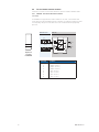
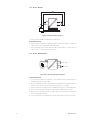
Figure 4.2: MPA5500 AC power adaptor
To fit the adaptor, locate the tongue of the adaptor into the top slot on the side of the MTL5500
module and press the adaptor until it fits closely to the body of the module, as shown.
Use double-insulated AC power cable with conductor parameters of 0.2–1.5mm
2
, or 0.25–
1.5mm
2
if using ferrules. Strip the outer insulation by no more than 30mm, then strip the inner
conductors by 8mm. Insert the cables appropriately in the cage-clamp connectors marked ‘L’
and ‘N’.
The incoming AC power must have some form of power disconnection device, such as a switch
or circuit breaker; a coupler that can be disconnected without the use of a tool; or a separable
plug, without a locking device, to mate with an adjacent socket outlet.
In addition, some form of cable anchorage must be used to relieve the cable conductors from
strain, including twisting, where they connect to the adaptor, and which will also protect the
insulation of the cable from abrasion.
WARNING
This adaptor is not suitable for use with MTL5000
range of
modules.
Direction of
removal of
MPA5500
Area required
for removal of
MPA5500
11
20
15.8
118.8
133
AC inputs
Top of DIN rail

INM 5500 Rev 10
8
4.3 Earth rail and tagging accessories
This section explains how to specify and assemble earth rail and tagging strip accessories for the
MTL5500 range.
The accessories consist of mounting brackets, earth rails, tagging strips and associated parts. They
provide facilities for earthing, terminating cable screens and tagging (identifying) the positions of
individual units.
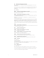
4.3.1 Parts list
IMB57 Insulating mounting block (Figures 4.3, 4.4 & 4.5)
One required at each end of a tagging strip/earth rail. Suitable for low-profile (7.5mm) and high-
profile (15mm) symmetrical DIN rail.
ERB57S Earth-rail bracket, straight (figure 4.3, 4.4 & 4.9)
Nickel-plated bus bar; supplied with two push fasteners, one earth-rail clamp (14mm, 35mm
2
) and
one earth cable clamp (10mm, 16mm
2
).
Note: ERB57S is the preferred choice of earth-rail bracket. It is usually fitted in the upper slot on
insulating mounting block IMB57.
Where the earth rail is required to be positioned at a lower height and to allow access to the IMB57
mounting screws, the straight earth-rail bracket ERB57S can be inserted in the lower slot, but only
after insulating mounting blocks IMB57 are clamped to the DIN rail. This may not be possible if, for
example, trunking is fitted. In this case, fit offset earth-rail bracket ERB570 (see figure 4.4 & 4.10) in
the upper slot: the mounting blocks can then be fitted in a restricted space with this bracket already
fitted.
ERB570 Earth-rail bracket, offset (figure 4.9)
Nickel-plated
bus bar
; supplied with two push fasteners, one earth-rail clamp (14mm, 35mm
2
) and
one earth cable clamp (10mm, 16mm
2
).
ERL7 Earth rail, 1m length (figure 4.9)
Nickel-plated bus bar; may be cut to length.
TAG57 Tagging strip, 1m length (figure 4.3, 4.4 & 4.6)
Cut to size. Supplied with tagging strip label.
TGL57 Tagging strip labels, set of 10 x 0.5m (figure 4.3 & 4.4)
Spares replacement, for use with TAG57 tagging strip.
MS010 DIN rail module spacer, 10mm, pack of 5 (figure 4.7)
Grey spacer; Used to provide 10mm air-circulation space between modules, if necessary.
ETM7 Earth terminal, bag of 50 (figure 4.8)
For terminating cable screens and 0V returns on the ERL7 earth rail. For cables ≥ 4mm
2
.
TH5000 Tag holder
Spares replacement.
Connectors (Figure 4.5)
Spares replacement: HAZ1-3, HAZ4-6, HAZ-CJC, PWR5000, SAF7-9, SAF10-12 (SAF1-3 and SAF4-6
grey connectors, also available for use in safe-area applications).
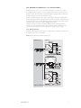
4.3.2 Assembly
4.3.2.1 Fitting earth rails
a) In upper position
Before fitting insulating mounting blocks IMB57, check that the swing nuts in the base of
each unit are turned back into the moulding. Locate the mounting blocks on the DIN rail in the
chosen position and tighten the screws (see figure 4.10). Check that the swing nuts rotate
correctly to locate underneath the flanges of the DIN rail.

INM 5500 Rev 10
9
TGL57
TAG57
ERB57
ERB570
ETM7
Snap off extension
when using IMB57
as central support
10mm Earth
clamp
ERB57S
in upper
position
ERB57S
in lower
position
IMB57
Push
fastener
14mm
Earth-rail
clamp
ERL7
THR2
IMB57
ERL7
HAZ1-3
HAZ4-6
TH5000
TAG57
TGL57
SAF7-9
SAF10-12
ERB57S
ETM7
PWR5000
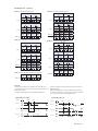
Figure 4.3: Assembly drawing showing part numbers
Figure 4.4: Mounting details
Figure 4.5: IMB57 Insulating mounting block
Figure 4.6: TAG57 Tagging strip, 1m length
Figure 4.7: MS010 DIN rail module spacers
Figure 4.8: ETM7 Earth terminals
Figure 4.9: Earth rails and clamps

INM 5500 Rev 10
10
Figure 4.10: Fitting IMB57
Slide a straight earth-rail bracket ERB57S into the upper slot in each mounting block. Push two
plastic push fasteners into each bracket to locate the brackets in the mounting blocks.
Cut earth rail ERL7 to the length needed. Slide the required number of ETM7 earth terminals
(5mm or 7mm wide) onto the rail. Clamp each end of the earth rail to earth-rail brackets ERB57S
using the terminal clamps (14mm, 35mm
2
) supplied. Fit an earth clamp (10mm, 16mm
2
) to the
free end of each earth-rail bracket.
Note: For lengths of earth-rail greater than 500mm, provide additional support by installing a
third IMB57 mounting block and earth-rail bracket, mid-way between the end mounting blocks.
Snap out the perforated extension between the lugs on this mounting block if a continuous
tagging strip is to be fitted (see figure 4.6).
b) In lower position, where at least 150mm clearance exists on one side, measured from the
edge of the mounting block.
As for a), but slide earth-rail brackets ERB57S into the lower slots in each mounting block.
c) In lower position, where there is insufficient clearance to fit earth-rail brackets ERB57S.
As for a), but slide offset earth-rail brackets ERB57O into the upper slot in each mounting
block before assembling the mounting blocks to the DIN rail. ERB57S brackets cannot be used
because they obscure the fixing screws on the mounting blocks.
4.3.2.2 Fitting tagging strips
Assemble mounting blocks IMB57 to the DIN rail as above. Cut TAG57 tagging strip and label to the
length needed, and insert label so that the appropriate side is visible. Clip the strip onto the lugs on
the mounting blocks. Hinge up the strip to provide access to the tops of the isolators.
Note: If necessary, provide additional support for long lengths of tagging strip by installing an
extra IMB57 mounting block mid-way between the end mounting blocks. Snap out the perforated
extension between the lugs on this mounting block.
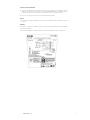
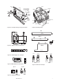
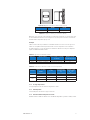
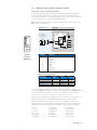
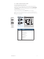
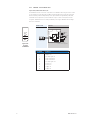
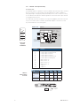
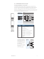
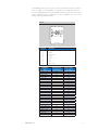
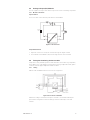
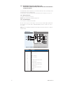
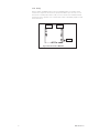
4.3.3 Completed assemblies
Figure 4.11 illustrates a complete assembly of MTL5500 isolators using the accessories mentioned
above.
The broken-line boxes either side of the assembly represent cable trunking, and the accompanying
dimensions represent the recommended minimum spacing between the trunking and the module
assemblies.

INM 5500 Rev 10
11
Colour Module no. Function
Yellow MTL5501-SR
Digital Inputs
White MTL551x
Red MTL552x Digital Outputs
Blue MTL5531/33 Vibration
Purple MTL5532 Pulse
Blue
MTL5541x
MTL5544x
Analogue Inputs
Green
MTL5546x
MTL5549x
Analogue Outputs
Blue MTL556x Fire & Smoke
Orange
MTL557x
MTL558x
Temperature inputs
Grey MTL5599 Dummy isolator
Table 4.2: MTL5500 front label colour coding
Figure 4.11: MTL5500 complete assembly

INM 5500 Rev 10
12
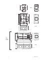
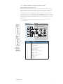
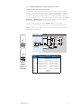
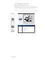
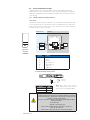
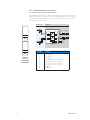
5 DX ENCLOSURES
Enclosures are usually selected on the basis of the number of units they will accommodate and
Table 5.1 shows the capacity of each of the enclosures. Figure 5.2 shows each type of enclosure
containing MTL5500 modules.
Table 5.1: DX range of enclosures - module capacities
Enclosure Number of MTL5500 isolators
16mm mounting pitch
DX070 4 (2*)
DX170 10 (8*)
(DX430) 26 (24*) no longer available
* Use these figures when two IMB57 mounting brackets for tagging/earth-rail accessories are included.
Note: The user should be aware that some workshop preparation may be required for the cable gland
plates before the enclosure is ready for on-site installation.
5.1 Environmental conditions
Environmental conditions that should be taken into account when installing DX enclosures include:-
See section
Maximum ambient temperature limits 5.1.1
Storage temperatures 5.1.2
Humidity 5.1.3
Corrosion resistance 5.1.4
Flammability 5.1.5
Impact resistance 5.1.6
Chemical resistance 5.1.7
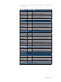
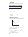
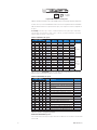
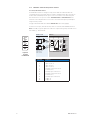
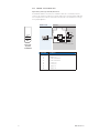
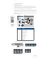
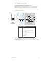
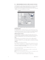
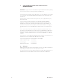
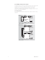
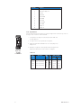
5.1.1 Maximum outside enclosure temperature limits
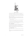
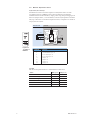
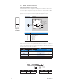
Figure 5.1: Graph depicting outside enclosure temperature limits for DX enclosures used
with MTL5500 isolators
The maximum outside enclosure temperature depends upon the total power dissipated by the
installed modules which, in turn, depends upon their number and type. It can also be influenced by
the Authority whose standards may need to be applied to the system, e.g. Baseefa, Factory Mutual
Research Corporation, Canadian Standards Association.
Figure 5.1 shows, in graphical form, the maximum outside enclosure temperatures (T
MO
) for given
levels of power dissipation.
The graph was derived from the following equation and should be used to calculate accurately the
suitability of any particular mix of modules.
T
MO
= 60°C - ∂T where ∂T = k
1
x P
P = total power (watts) dissipated by modules in an enclosure
k
1
= is a dissipation constant for a given enclosure and module . Select the relevant value from
Table 5.2.
(60°C is the temperature inside the enclosure)
60
40
20
10
30
50
0
10 20 30 40
Power dissipation (watts)
Max. outside enclosure
temperature (°C)
Enclosures
DX070
DX170
DX430
Page is loading ...
Page is loading ...
Page is loading ...
Page is loading ...
Page is loading ...
Page is loading ...
Page is loading ...
Page is loading ...
Page is loading ...
Page is loading ...
Page is loading ...
Page is loading ...
Page is loading ...
Page is loading ...
Page is loading ...
Page is loading ...
Page is loading ...
Page is loading ...
Page is loading ...
Page is loading ...
Page is loading ...
Page is loading ...
Page is loading ...
Page is loading ...
Page is loading ...
Page is loading ...
Page is loading ...
Page is loading ...
Page is loading ...
Page is loading ...
Page is loading ...
Page is loading ...
Page is loading ...
Page is loading ...
Page is loading ...
Page is loading ...
Page is loading ...
Page is loading ...
Page is loading ...
Page is loading ...
Page is loading ...
Page is loading ...
Page is loading ...
Page is loading ...
Page is loading ...
Page is loading ...
Page is loading ...
Page is loading ...
Page is loading ...
Page is loading ...
Page is loading ...
Page is loading ...
Page is loading ...
Page is loading ...
Page is loading ...
Page is loading ...
Page is loading ...
Page is loading ...
Page is loading ...
Page is loading ...
Page is loading ...
Page is loading ...
Page is loading ...
Page is loading ...
Page is loading ...
Page is loading ...
Page is loading ...
Page is loading ...
-
 1
1
-
 2
2
-
 3
3
-
 4
4
-
 5
5
-
 6
6
-
 7
7
-
 8
8
-
 9
9
-
 10
10
-
 11
11
-
 12
12
-
 13
13
-
 14
14
-
 15
15
-
 16
16
-
 17
17
-
 18
18
-
 19
19
-
 20
20
-
 21
21
-
 22
22
-
 23
23
-
 24
24
-
 25
25
-
 26
26
-
 27
27
-
 28
28
-
 29
29
-
 30
30
-
 31
31
-
 32
32
-
 33
33
-
 34
34
-
 35
35
-
 36
36
-
 37
37
-
 38
38
-
 39
39
-
 40
40
-
 41
41
-
 42
42
-
 43
43
-
 44
44
-
 45
45
-
 46
46
-
 47
47
-
 48
48
-
 49
49
-
 50
50
-
 51
51
-
 52
52
-
 53
53
-
 54
54
-
 55
55
-
 56
56
-
 57
57
-
 58
58
-
 59
59
-
 60
60
-
 61
61
-
 62
62
-
 63
63
-
 64
64
-
 65
65
-
 66
66
-
 67
67
-
 68
68
-
 69
69
-
 70
70
-
 71
71
-
 72
72
-
 73
73
-
 74
74
-
 75
75
-
 76
76
-
 77
77
-
 78
78
-
 79
79
-
 80
80
-
 81
81
-
 82
82
-
 83
83
-
 84
84
-
 85
85
-
 86
86
-
 87
87
-
 88
88


Ask a question and I''ll find the answer in the document
Finding information in a document is now easier with AI
Related papers
-
Eaton Crouse-Hinds MTL GECMA WS 24 User manual
-
Eaton MTL7715 Plus User manual
-
Eaton MTL4500 Series User manual
-
-
-
Eaton Crouse Hinds series Installation guide
-
Eaton Crouse-hinds series Technical Support
-
Eaton MTL K522 Operating instructions
-
-
Other documents
-
Dwyer Series MTL5541 User manual
-
hyfire HFI-DMBS-05 User manual
-
IFM N0531A Operating instructions
-
 C Prox Ltd MINI-PROX User manual
-
Toshiba RT318 User manual
-
Eurotherm 902-904 Handbook Owner's manual
-
MSA Ultima® XL/XT Series Gas Monitors Quick start guide
-
-
-
Lowell Z Rail User manual
