
ABB AB / Jokab Safety Varlabergsvägen 11, SE-434 39 Kungsbacka, Sweden
www.jokabsafety.com
Original instructions
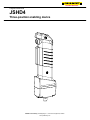
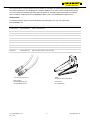
JSHD4
Three-position enabling device

2TLC172052M0201, rev. A 2 www.jokabsafety.com
2011-10-06
Read and understand this document
Please read and understand this document before using the products. Please consult your ABB/JOKAB SAFETY
representative if you have any questions or comments.
WARRANTY
ABB/JOKAB SAFETY’s exclusive warranty is that the products are free from defects in materials and workmanship
for a period of one year (or other period if specified) from date of sale by ABB/JOKAB SAFETY.
ABB/JOKAB SAFETY MAKES NO WARRANTY OR REPRESENTATION, EXPRESSED OR IMPLIED,
REGARDING NON-INFRINGEMENT, MERCHANTABILITY, OR FITNESS FOR PARTICULAR PURPOSE OF
THE PRODUCTS, ANY BUYER OR USER ACKNOWLEDGES THAT THE BUYER OR USER ALONE HAS
DETERMINED THAT THE PRODUCTS WILL SUITABLY MEET THE REQUIREMENTS OR THEIR INTENDED
USE. ABB/JOKAB SAFETY DISCLAIMS ALL OTHER WARRANTIES, EXPRESSED OR IMPLIED.
LIMITATIONS OF LIABILITY
ABB/JOKAB SAFETY SHALL NOT BE RESPONSIBLE FOR SPECIAL, INDIRECT, OR CONSEQUENTIAL
DAMAGES, LOSS OF PROFITS OR COMMERCIAL LOSS IN ANY WAY CONNECTED WITH THE PRODUCTS,
WHETHER SUCH CLAIM IS BASED ON CONTRACT, WARRANTY, NEGLIGENCE, OR STRICT LIABILITY.
In no event shall responsibility of ABB/JOKAB SAFETY for any act exceed the individual price of the product on
which liability asserted.
IN NO EVENT SHALL ABB/JOKAB SAFETY BE RESPONSIBLE FOR WARRANTY, REPAIR, OR OTHER
CLAIMS REGARDING THE PRODUCTS UNLESS ABB/JOKAB SAFETY’S ANALYSIS CONFIRMS THAT THE
PRODUCTS WERE PROPERLY HANDLED, STORED, INSTALLED, AND MAINTAINED AND NOT SUBJECT TO
ABUSE, MISUSE, OR INAPPROPRIATE MODIFICATION OR REPAIR.
SUITABILITY FOR USE
ABB/JOKAB SAFETY shall not be responsible for conformity with any standards, codes, or regulations that apply
to the combination of products in the customer’s application or use of the product. At the customer’s request,
ABB/JOKAB SAFETY will provide applicable third party certification documents identifying ratings and limitations of
use that apply to the products. This information by itself is not sufficient for a complete determination of the
suitability of the products in combination with the end product, machine, system, or other application or use.
The following are some examples of applications for which particular attention must be given. This is not intended
to be an exhaustive list of all possible uses of the products, nor is it intended to imply that the uses listed may be
suitable for the products:
Outdoor use, uses involving potential chemical contamination or electrical interference, or conditions or uses not
described in this document.
Nuclear energy control systems, combustion systems, railroad systems, aviation systems, medical equipment,
amusement machines, vehicles, and installations subject to separate industry or government regulations.
Systems, machines, and equipment that could present a risk to life or property.
Please know and observe all prohibitions of use applicable to the products.
NEVER USE THE PRODUCTS FOR AN APPLICATION INVOLVING SERIOUS RISK TO LIFE OR PROPERTY
WITHOUT ENSURING THAT THE SYSTEM AS A WHOLE HAS BEEN DESIGNED TO ADDRESS THE RISKS,
AND THAT THE ABB/JOKAB SAFETY PRODUCT IS PROPERLY RATED AND INSTALLED FOR THE
INTENDED USE WITHIN THE OVERALL EQUIPMENT OR SYSTEM.
PERFORMANCE DATA
While every effort has been taken to ensure the accuracy of the information contained in this manual ABB/JOKAB
SAFETY cannot accept responsibility for errors or omissions and reserves the right to make changes and
improvements without notice. Performance data given in this document is provided as a guide for the user in
determining suitability and does not constitute a warranty. It may represent the result of ABB/JOKAB SAFETY’S
test conditions, and the users must correlate it to actual application requirements. Actual performance is subject to
the ABB/JOKAB SAFETY Warranty and Limitations of Liability.

2TLC172052M0201, rev. A 3 www.jokabsafety.com
2011-10-06
Table of Contents
1 Introduction ......................................................................................................................................... 4
Scope ................................................................................................................................................................ 4
Audience ........................................................................................................................................................... 4
Prerequisites ...................................................................................................................................................... 4
Special notes ..................................................................................................................................................... 4
2 Overview .............................................................................................................................................. 5
General description ............................................................................................................................................ 5
Safety regulations .............................................................................................................................................. 5
Function description ........................................................................................................................................... 6
3 Connections ........................................................................................................................................ 7
Top parts ........................................................................................................................................................... 7
Anti-tamper PCB ................................................................................................................................................ 8
Bottom parts ...................................................................................................................................................... 8
Connection examples....................................................................................................................................... 11
4 Installation and maintenance ........................................................................................................... 12
Assembly instructions ...................................................................................................................................... 12
Installation precautions .................................................................................................................................... 13
Maintenance .................................................................................................................................................... 13
5 Operation ........................................................................................................................................... 14
Three-position button ....................................................................................................................................... 14
Front and top button ......................................................................................................................................... 14
Anti-tampering device ...................................................................................................................................... 14
LED indication.................................................................................................................................................. 15
6 Model overview .................................................................................................................................. 16
Separate parts, to be assembled by customer .................................................................................................. 16
Complete handles, ready to use ....................................................................................................................... 16
Accessories ..................................................................................................................................................... 17
7 Technical data ................................................................................................................................... 18
Dimensions ...................................................................................................................................................... 19
8 EC Declaration of conformity ........................................................................................................... 20

2TLC172052M0201, rev. A 4 www.jokabsafety.com
2011-10-06
1 Introduction
Scope
The purpose of these instructions is to describe the three-position enabling device JSHD4 and to provide the
necessary information required for assembly, installation and maintenance. The instructions also include
information necessary to connect JSHD4 to a safety circuit. Note that JSHD4 can be connected to both safety
relays in the RT-series and safety-PLC Pluto.
Specific AS-i data and other instructions for enabling devices with AS-i nodes are left out and can be found in the
instructions manual for JSHD4 AS-i.
Audience
This document is intended for authorized installation personnel.
Prerequisites
It is assumed that the reader of this document has knowledge of the following:
Basic knowledge of ABB/Jokab Safety products.
Knowledge of safety devices and safety circuits.
Knowledge of machine safety.
Special notes
Pay attention to the following special notes in the document:
Warning!
Danger of severe personal injury!
An instruction or procedure which, if not carried out correctly, may result in injury to the technician
or other personnel.
Caution!
Danger of damage to the equipment!
An instruction or procedure which, if not carried out correctly, may damage the equipment.
NB: Notes are used to provide important or explanatory information.

2TLC172052M0201, rev. A 5 www.jokabsafety.com
2011-10-06
2 Overview
General description
JSHD4 is a dual channel three-position enabling device, intended for use in hazardous areas where no other
protection is possible or practical. The device as a stand-alone unit is not sufficient for this task and must be
connected to a suitable control unit (safety relay or safety-PLC) with two channel inputs and short-circuit detection.
Also, the machinery or equipment causing the potential danger may need to be set in jog-mode or by other means
limited in movement, speed, temperature etc.
Two three-position push buttons operated by one common surface ensures a high level of safety, both when
released and when pressed into the third and final position. The safety contacts are closed only in the middle
position, but are opened if pressed further and remain open during the return to the top (resting) position.
The anti-tampering device consists of a capacitive sensor and an accelerometer. By combining these sensors the
device can be used to determine if an operator is holding the enabling device. This can be used if there is any risk
for tampering of the enabling device.
JSHD4 is based on a modular system that allows for a number of different versions of a complete enabling device
to be created, using different top parts (handles) and bottom parts (with different cables and connectors, AS-i
nodes, emergency stop, etc). There are also a number of accessories available, such as fittings for safety
switches/sensors, anti-tampering electronics, cables and resting stations. For more information, see chapter Model
overview.
For more details on JSHD4 operation, see chapter Operation.
Warning! The anti-tampering device is not a safety function; the safety relies on the three-position button being
operated as intended.
Safety regulations
Warning!
Carefully read through this entire
manual before using the device.
The devices shall be installed by a trained electrician following the Safety regulations, standards and the Machine
directive.
Failure to comply with instructions, operation that is not in accordance with the use prescribed in these instructions,
improper installation or handling of the device can affect the safety of people and the plant.
For installation and prescribed use of the product, the special notes in the instructions must be carefully observed
and the technical standards relevant to the application must be considered.
In case of failure to comply with the instructions or standards, especially when tampering with and/or modifying the
product, any liability is excluded.

2TLC172052M0201, rev. A 6 www.jokabsafety.com
2011-10-06
Function description
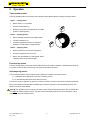
Three-position principle
A three-position enabling switch provides signals that:
when activated, allows a machine or other equipment to be initiated by a separate start control, and
when de-activated, initiate a stop function and prevent an initiation of machine/equipment operation.
A three-position switch can also be used as a hold-to-run device. Used as such a device, the machine may already
be running and by putting the device in position 2 (ON) and removing it from a holder with position sensor, another
guarding system (light curtain, door interlock switch etc) is muted and the restricted area can be entered without
stopping the machine. Certain limitations in time, speed etc may be needed to ensure an acceptable safety level.
Two three-position switches are used and operated simultaneously, to provide a dual channel safety system.
The three positions are designated as follows:
Position 1: OFF state of the contact (actuator is not pressed)
Position 2: ON state of the contact (actuator is pressed to the normal enabling position)
Position 3: OFF state of the contact (actuator is fully depressed).
When released, the actuator always returns to position 1, regardless of whether it was in position 2 or 3. During this
return movement, the contact(s) remain open.
In addition to the three-position safety function, JSHD4 can be equipped other features such as push buttons for
selectable functions (start, stop, gripping tool, etc), an emergency stop or an anti-tampering sensor.
Anti-tampering device
Many versions of JSHD4 can be equipped with a sensor that prevents tampering (for instance by keeping the
three-position switches in ON-position using a rubber band or similar). The sensor detects a human hand and also
the small movements/vibrations that are normal when holding the handle. If both these requirements are fulfilled
(detected), a contact is closed. When properly connected, the contact can be used to open the safety circuit, and
thus prohibit tampering.
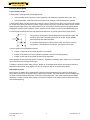
The symbol for three-position switches illustrates the three positions (OFF, ON
and OFF) with O and I, the pushing force from left to right, and the possible
switching travels (IEC 60947-5-8:2006).
An important characteristic for a three-position switch is that when returning
from position 3, the ON state is not reached – the contacts remain open.

2TLC172052M0201, rev. A 7 www.jokabsafety.com
2011-10-06
3 Connections
Top parts
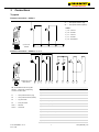
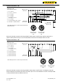
Electrical connections – JSHD4-1
Electrical connections – JSHD4-2, -3, -4, -5
1 3 7 2 4 8 6 5 9 12 10 1
1
S1 S2 S3 S4
LED1 LED2
Female pins in 2x8
Molex female
S1 = Three-position button #1 (top)
S2 = Three-position button #2 (bottom)
S3 = Top push button
S4 = Front push button
LED 1 = Red LED
LED 2 = Green LED
# Description JSHD4-2 JSHD4-3 JSHD4-4 JSHD4-5
1 ) S1 – Common x x x x
2 ) S2 – Common x x x x
3 ) S1 – Actuated x x x x
4 ) S2 – Actuated x x x x
5 ) +24 VDC (LED 2) x x x x
6 ) +24 VDC (LED 1) x x x x
7 ) S1 – Not actuated x x x x
8 ) S2 – Not actuated x x x x
9 ) 0 VDC (LED 1, LED 2) x x x x
10 ) S3 – Actuated x - - x
11 ) S4 – Actuated x - x -
12 ) S3, S4 – Common x - x x
NB: The 2x8 Molex female on top parts
JSHD4-2...5 mates with corresponding
connector on bottom parts.
1 2 3 4 5
S2 S1
JSHD4-1:
1 ) S2 – Common
2 ) S2 – Actuated
3 ) S1 – Common
4 ) S1 – Actuated
5 ) S2 – Not actuated
5-pole screw
terminal
S1 = Three-position button #1 (top)
S2 = Three-position button #2 (bottom)

2TLC172052M0201, rev. A 8 www.jokabsafety.com
2011-10-06
Anti-tamper PCB
The optional anti-tamper PCB may be connected separately or in series with one of the three-position push buttons
(S1 or S2).
Warning!
When the anti-tamper PCB is connected in series with a three-position button, one out of the two alternatives
below must be implemented to ensure proper functionality of the three-position switch:
1. Simultaneous check of the two channels at actuation of the switches.
2. Supervised reset of the three-position button connected in series with the anti-tamper PCB.
Bottom parts
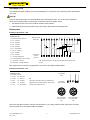
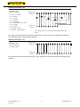
Electrical connections – AB
NB: 12-pole Cannon connector, wiring suited for any monitor. Anti-tamper PCB is possible.
Electrical connections – AC
NB: 5-pole male M12 connector. Suited for top part JSHD4-1 only. Wiring suited for safety relays in the RT-series
and Pluto safety-PLC. Anti-tamper PCB is not possible.
Bottom part – AC:
5-pole M12 connector
1 ) Brown: S2 – Common
2 ) White: S1 – Common
3 ) Blue: S2 – Actuated
4 ) Black: S1 – Actuated
5 ) Grey: S1 – Not actuated
NB:
Connections according to factory assembled units.
Suggested use for manual assembly. Cable colours
for each pin according to the list.
1 2 3 4 5
5-pole male
M12-connector
5x individual
wires
M12 5-pole male
seen from cable
side
2
1
5
4
3
M12 5-pole female
seen from cable
side
1
2
5
3
4
1
2
3
4
5
6
7
8
9
1
0
1
1
1
2
1
3
1
4
1
5
1
6
A B C D E F G H J K L M
Male pins in 2x8
Molex male
12-pole male
Cannon
connector
Bottom part - AB:
12-pole male Cannon connector
A ) S1 – Common*
B ) S1 – Actuated
C ) S2 – Common
D ) S2 – Actuated
E ) S1 – Not actuated
F ) S3, S4 – Common
G ) S3 – Actuated
H ) S4 – Actuated
J ) +24 VDC (anti-tamper)
K ) 0 VDC (anti-tamper, LED 1, LED 2)
L ) Anti-tamper – Common
M ) Anti-tamper – Operator detected
* NB: COM signal must be +24 VDC for proper LED and anti-tamper PCB
function.

2TLC172052M0201, rev. A 9 www.jokabsafety.com
2011-10-06
Electrical connections – AD
NB: 8-pole male M12 connector with wiring suitable for safety relays in the RT-series and Pluto safety-PLC. A
jumper must be placed over pins 14-16 on the 2x8 Molex connector if an anti-tamper PCB is not used.
Electrical connections – AE
NB: 8-pole male M12 connector with wiring suitable for safety relays in the RT-series. An emergency stop push
button is attached on the bottom part and is connected to pins 13-16 on the 2x8 Molex connector. Anti-tamper PCB
or extra push buttons are not possible for this unit.
1
2
3
4
5
6
7
8
9
1
0
1
1
1
2
1
4
1
3
1
5
1
6
1 2 3 4 5 6 7 8
Male pins in 2x8
Molex male
8-pole male
M12-connector
Bottom part – AE:
8-pole male M12-connector
1 ) S2 – Common
2 ) S1 – Common*
3 ) S2 – Actuated
0 VDC (LED 1, LED 2)
4 ) S1 – Actuated
5 ) E1 (E-stop channel 1)
6 ) E1 (E-stop channel 1)
7 ) E2 (E-stop channel 2)
8 ) E2 (E-stop channel 2)
M12 8-pole male
seen from cable
side
21
7
6
5
4
3
8
M12 8-pole female
seen from cable
side
12
3
4
5
6
7
8
* NB: COM signal must be +24 VDC for proper LED function.
1
2
3
4
5
6
7
8
9
1
0
1
1
1
2
1
3
1
4
1
5
1
6
1 2 3 4 5 6 7 8
Male pins in 2x8
Molex male
8-pole male
M12-connector
Bottom part – AD:
8-pole male M12-connector
1 ) S2 – Common
2 ) S1, S3, S4 – Common*
3 ) S3 – Actuated
4 ) S4 – Actuated
5 ) S1 – Actuated
Anti-tamper – Common
6 ) S2 – Actuated
7 ) 0 VDC (anti-tamper, LED 1, LED 2)
8 ) Anti-tamper – Operator detected
Extra jumper.
Required if no anti-
tamper is used.
M12 8-pole male
seen from cable
side
21
7
6
5
4
3
8
M12 8-pole female
seen from cable
side
12
3
4
5
6
7
8
* NB: COM signal must be +24 VDC for proper LED and anti-
tamper PCB function.

2TLC172052M0201, rev. A 10 www.jokabsafety.com
2011-10-06
Electrical connections – AH
NB: 10-pole screw terminal with wiring suited for safety relays in the RT-series or Pluto safety-PLC. Intended for
user assembled cable. Anti-tamper PCB is possible.
Electrical connections – AJ
NB: 16-pole screw terminal, wiring suited for any monitor. Intended for user assembled cable. Anti-tamper PCB is
possible.
1
2
3
4
5
6
7
8
9
1
0
1
1
1
2
1
4
1
3
1
5
1
6
Male pins in 2x8
Molex male
16-pole screw
terminal
Bottom part – AJ:
16-pole screw terminal
According to top part.
1
2
3
4
5
6
7
8
9
1
0
1
1
1
2
1
4
1
3
1
5
1
6
1 2 3 4 5 6 7 8 9 10
Male pins in 2x8
Molex male
10-pole screw
terminal
Bottom part – AH:
10-pole screw terminal
1 ) S1, S3, S4 – Common*
2 ) S2 – Common
3 ) S1 – Actuated
4 ) S2 – Actuated
5 ) S1 – Not actuated
6 ) 0 VDC (anti-tamper, LED 1, LED 2)
7 ) S3 – Actuated
8 ) S4 – Actuated
9 ) Anti-tamper – Common
10 ) Anti-tamper – Operator detected
* NB: COM signal must be +24 VDC for proper LED and anti-tamper PCB
function.

2TLC172052M0201, rev. A 11 www.jokabsafety.com
2011-10-06
Connection examples
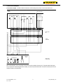
Connection example – JSHD4-2-AB-A connected to an RT6 safety relay via the 12-wire cable JSHK10-K
NB: The anti-tamper unit is connected in series with one three-position channel (S1). The supervised reset (input
X1) is required to maintain highest level of safety. Top and front push buttons are not shown connected, but can be
wired according to user demands.
**
2 2 2
2313 14 42 Y14 Y2424 33 34 41
S13
11
A2A1 X1
2
1
1&2In
S23 S24 S53Y13S14
1
S34 S44 X4
L
24V
0V
RT6
LED1 LED2
S1 S2 S3 S4
1 2 3 4 5
+ COM - NO NC
1 3 7 2 4 1468 10 1312 155 119 16
1 3 7 2 4 1468 10 1312 155 119 16
A B E C D G JF LHK M
JOKAB SAFETY
Handle
JSHD4-2 Anti-tamper PCB
Bottom part
AB
Cable
JSHK10-K
Safety relay
RT6 24 VDC
Test/Auto
reset
Anti-tamper

2TLC172052M0201, rev. A 12 www.jokabsafety.com
2011-10-06
4 Installation and maintenance
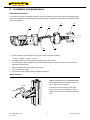
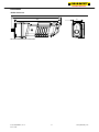
Assembly instructions
If a complete and ready to install unit is at hand, connect the cable to the control unit and connect enabling device
to the cable. Otherwise, first assemble top and bottom part and, if needed, the anti-tampering unit (PCB) following
the instructions below.
1. If used, insert pins from anti-tamper unit (D) into connector (B) from handle (A).
13: Red 14: Black 15: Blue
16: Pink
2. Insert PCB as shown, components facing forward. Push it all the way in.
3. If no anti-tamper is used, a jumper may need to be inserted between positions 14 and 16 in connector (B),
depending on bottom part.
4. Remove protective liner from gasket (C) on handle.
5. Join connectors (B) and (E).
6. Press bottom part (F) against handle and tighten screws (G).
JSM55 installation
A
C
D
F
G
B
E
JSM 55 is designed to fit onto ABB/Jokab Safety
Quick-Guard aluminium fencing extrusions, but
can be used on any flat surface.
If the two pre-mounted nuts are used, place
them in the groove in the extrusion, and then
loosen each screw three turns before tightening
them.
2. 2-3Nm
SW=4mm
1. 1080°

2TLC172052M0201, rev. A 13 www.jokabsafety.com
2011-10-06
Installation precautions
Warning! All the safety functions must
be tested before starting up the system.
Maintenance
Warning!
The safety functions and the mechanics shall be tested regularly, at least once every year to confirm that all the
safety functions are working properly (EN 62061:2005).
In case of breakdown or damage to the product, contact the nearest ABB/Jokab Safety Service Office or reseller.
Do not try to repair the product yourself since it may accidentally cause permanent damage to the product,
impairing the safety of the device which in turn could lead to serious injury to personnel.

2TLC172052M0201, rev. A 14 www.jokabsafety.com
2011-10-06
5 Operation
Three-position button
The three possible positions of the main button represent three different states according to the figure below.
Front and top button
The front and top button functionality are user defined and can be used for start/stop of individual movements etc.
They have no intrinsic safety and are only to be used for subordinate functions.
Anti-tampering device
The anti-tampering device has two requirements to determine if JSHD4 is operated correctly:
1 ) A capacitive sensor determines if the device is held by a hand.
2 ) An accelerometer determines if the device is moving.
The internal contact is opened if the device is not held by a hand or if it has not moved for more than 20 seconds.
NB: Not all models are equipped with the additional (front and/or top) button or the anti-tampering device, see
Model overview for further details.
Warning! The signals from the front and/or top button, as well as the anti-tampering device, are non-failsafe and
must never
be used for safety functions. They may enhance the safety level but can not be used alone, only in
combination with other safety functions.
1
.
2.
3
.
State 1 – ”Resting state”:
Button rested, i.e. not pressed.
Process not allowed to run.
Waiting for the button to be pressed into its middle
position (”operating state”).
State 2 – ”Operating state”:
Button actuated, pressed into its middle position.
Process is allowed to run.
Process is stopped if the button is released or
pressed to its end position (“stopping state”).
State 3 – ”Stopping state”:
Button is pressed to its third and final position.
Process is stopped by the control unit.
Button must be released into “resting state” before
“operating state” can be reached again.

2TLC172052M0201, rev. A 15 www.jokabsafety.com
2011-10-06
LED indication
This section does not apply to JSHD4-1.
LEDs on the top of the device
Red Green Description
OFF OFF
A ) No power or LED function not connected OR
B ) Power on, safety channel 1 in OK position but anti-tamper not OK
ON OFF Power on, safety channel 1 not in OK position
ON ON Power on, device faulty, muted, or improperly connected.
OFF ON Power on, safety channel 1 in OK position (and anti-tamper OK)

2TLC172052M0201, rev. A 16 www.jokabsafety.com
2011-10-06
6 Model overview
A complete three-position device consists of one top part and one bottom part. It is also possible to add an optional
anti-tampering electronic unit to most combinations of top and bottom parts. These three parts can be ordered as
one factory assembled unit or as separate parts to be assembled by a user with the necessary training and
knowledge in machine safety. A full list of all parts with descriptions and possible combinations can be found at
www.jokabsafety.com.
Separate parts, to be assembled by customer
Type Article number Description
JSHD4-1 2TLJ020006R2100 Top part, no buttons, no LEDs, no possibility for anti-tamper.
JSHD4-2 2TLJ020006R2200 Top part, top and front button, LEDs, possibility for anti-tamper.
JSHD4-3 2TLJ020006R2300 Top part, no buttons, LEDs, possibility for anti-tamper.
JSHD4-4 2TLJ020006R2400 Top part, front button, LEDs, possibility for anti-tamper.
JSHD4-5 2TLJ020006R2500 Top part, top button, LEDs, possibility for anti-tamper.
Anti-tamper 2TLJ020005R0900 Anti-tamper unit
AA 2TLJ020005R1000 Bottom part, cable gland.
AB 2TLJ020005R1100 Bottom part, 12-pole connector.
AC 2TLJ020005R1200 Bottom part, 5-pole M12 connector.
AD 2TLJ020005R1300 Bottom part, 8-pole M12 connector.
AE 2TLJ020005R1400 Bottom part, 8-pole M12 connector with E-stop.
AF 2TLJ020005R1500 Bottom part, 4-pole M12 connector, 2 AS-i nodes (safe + standard node).
AG 2TLJ020005R1600 Bottom part, 4-pole M12 connector, 1 AS-i node (safe node).
AH 2TLJ020005R1700 Bottom part, 10-pole screw terminal, cable gland.
AJ 2TLJ020005R1800 Bottom part, 16-pole screw terminal, cable gland.
Complete handles, ready to use
JSHD4-1 JSHD4-2 JSHD4-3 JSHD4-4 JSHD4-5
AA 2TLJ019995R0000 - - - -
AB - 2TLJ019995R0200 2TLJ019995R1200 2TLJ019995R2400 2TLJ019995R3400
AB-A - 2TLJ019995R0300 2TLJ019995R1300 2TLJ019995R2500 2TLJ019995R3500
AC 2TLJ019995R0100 - - - -
AD - 2TLJ019995R0400 2TLJ019995R1400 2TLJ019995R2600 2TLJ019995R3600
AD-A - 2TLJ019995R0500 2TLJ019995R1500 2TLJ019995R2700 2TLJ019995R3700
AE - - 2TLJ019995R1600 - -
AF - 2TLJ019995R0600 2TLJ019995R1700 2TLJ019995R2800 2TLJ019995R3800
AF-A - 2TLJ019995R0700 2TLJ019995R1800 2TLJ019995R2900 2TLJ019995R3900
AG - - 2TLJ019995R1900 - -
AH - 2TLJ019995R0800 2TLJ019995R2000 2TLJ019995R3000 2TLJ019995R4000
AH-A - 2TLJ019995R0900 2TLJ019995R2100 2TLJ019995R3100 2TLJ019995R4100
AJ - 2TLJ019995R1000 2TLJ019995R2200 2TLJ019995R3200 2TLJ019995R4200
AJ-A - 2TLJ019995R1100 2TLJ019995R2300 2TLJ019995R3300 2TLJ019995R4300
NB: A darker square in the table indicates that anti-tamper is not possible with this combination.

2TLC172052M0201, rev. A 17 www.jokabsafety.com
2011-10-06
Not all combinations of top and bottom parts are possible or meaningful. The table above shows the part number
for possible combinations. The designation is created as JSHD4-X-YY-Z, where X is the number for the top part,
YY the two letters for the bottom part and Z means (if present) A: anti-tamper electronics included. A complete
order information would look like 2TLJ019995R0000 JSHD4-1-AA or 2TLJ019995R0700 JSHD4-2-AF-A.
Accessories
Accessories and spare parts are ordered separately and assembled by the user. For a full list see
www.jokabsafety.com.
Type Article number Description
Anti-tamper PCB 2TLJ020005R0900
Anti-tamper electronics, can be field fitted but will not work with all bottom parts and not with
JSHD4-1. See table above.
JSHK10-K 2TLJ020003R1100 10 m cable with 12-pole connector (for bottom part AB etc).
JSHK60S4 2TLJ020103R3200 6 m spiral cable with 12-pole connector (for bottom part AB etc).
JSM 55 2TLJ040005R0500 Wall fixing for three-position device
JSM 50H 2TLJ020205R6300 Fitting for Eden sensor (Eva unit).
JSM 50G 2TLJ020205R6400 Plate for JSNY5 actuators.
M12-C101 2TLJ020056R1000 10 m cable with 5-pole M12-connector (for bottom part AC etc).
M12-C103 2TLJ020056R4000 10 m cable with 8-pole M12-connector (for bottom part AD etc).
Gasket 2TLJ020200R1200 Gasket between handle and bottom part (spare part).
Cable gland 2TLJ020203R1700 Gland with cable protection, M16 (spare part).
JSM55
Wall fixing for three-position device
Article number:
2TLJ040005R0500
10 m cable with M12-connector
Article numbers:
2TLJ020056R1000 (5-pole)
2TLJ020056R4000 (8-pole)

2TLC172052M0201, rev. A 18 www.jokabsafety.com
2011-10-06
7 Technical data
Manufacturer
Address ABB AB / JOKAB SAFETY
Varlabergsvägen 11
SE-434 39 Kungsbacka
Sweden
Power supply
Operating voltage 24 VDC ± 10% at +20° C ambient temperature
Maximum current allowed Three-position channel: 20 mA
Push button: 500 mA
General
Protection class IP65
Ambient temperature -10…+50° C
Size See drawing
Operating force Approx. 15N for three-position buttons (ON)
Approx. 45N for three-position buttons (OFF)
Approx. 2.5N for top/front push button
Weight Approx 0.2 kg without cable
Material Handle: Polyamide and Noryl.
Rubber: Neoprene
Colour Yellow and black
Connector Cable or contact depending on version.
Mechanical life 10
6
cycles top to middle position
10
5
cycles middle to bottom position, and top/front button.
Warning!
When connecting the enabling device to a control unit, make a function check immediately to detect any short circuits or two channel faults.
Safety / Harmonized Standards
Conformity European Machinery Directive 2006/42/EC
EN ISO 12100-1:2010, EN 954-1:1996/EN ISO 13849-1:2008, EN 60204-1:2006+A1:2009
EN ISO 13849-1 Performance level: PL e, category 4
B
10d
: 2,000,000 (to middle position)
B
10d
: 968,000 (to bottom position)
EN 954-1 Category 4
Certificates Inspecta

2TLC172052M0201, rev. A 19 www.jokabsafety.com
2011-10-06
Dimensions
JSHD4 dimensions
NB: All measurements in millimetres.
60
34
186
2
0
0

2TLC172052M0201, rev. A 20 www.jokabsafety.com
2011-10-06
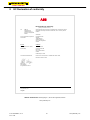
8 EC Declaration of conformity
ABB AB / JOKAB SAFETY Varlabergsvägen 11, SE-434 39 Kungsbacka, Sweden
www.jokabsafety.com
www.abb.com
www.jokabsafety.com
Original
EC Declaration of conformity
(according to 2006/42/EC, Annex 2A)
We ABB AB
JOKAB SAFETY
Varlabergsvägen 11
SE-434 39 Kungsbacka
Sweden
declare that the safety components of JOKAB SAFETY manufacture with type
designations and safety functions as listed below, are in conformity with the
Directive
2006/42/EC
Person authorised to compile the
technical file
Lars-Magnus Felth
ABB AB
JOKAB SAFETY
Varlabergsvägen 11
SE-434 39 Kungsbacka
Sweden
Product
Certificate
Three position device, JSHD4 11-SKM-CM-0110
Notified Body Inspecta Sweden AB
Box 30100
SE-104 25 Stockholm
Sweden
Notified Body No. 0409
Used harmonized standards EN ISO 12100-1:2010,EN 954-1:1996/EN ISO 13849-1:2008,
EN 60204-1:2006+A1:2009
Mats Linger
PRU Manager
Kungsbacka 2011-03-04
-
 1
1
-
 2
2
-
 3
3
-
 4
4
-
 5
5
-
 6
6
-
 7
7
-
 8
8
-
 9
9
-
 10
10
-
 11
11
-
 12
12
-
 13
13
-
 14
14
-
 15
15
-
 16
16
-
 17
17
-
 18
18
-
 19
19
-
 20
20


Ask a question and I''ll find the answer in the document
Finding information in a document is now easier with AI
Related papers
-
ABB Tina 7A Original Instructions Manual
-
-
-
-
-
-
ABB MKey8ER Original Instructions Manual
-
-
-
Other documents
-
 Cables Direct RB-520 Datasheet
-
 ABB - JOKAB 2TLA050009R0112 Operating instructions
-
 Pfister RT6-5WRY Dimensions Guide
-
 Pfister RT6-5WRY Specification
-
Tannoy CMS 803DC PI User manual
-
Diamond Systems PLT-T40N-2G User manual
-
Molex BradControl HarshIO 600 eIP User manual
-
schmersal AES 3075 24 VDC Operating instructions
-
-
Elvaco CMa35 Quick Manual


