Page is loading ...

COPYRIGHT © MARCH, 2017 BY GRIZZLY INDUSTRIAL, INC.
WARNING: NO PORTION OF THIS MANUAL MAY BE REPRODUCED IN ANY SHAPE
OR FORM WITHOUT THE WRITTEN APPROVAL OF GRIZZLY INDUSTRIAL, INC.
#JH18892 PRINTED IN TAIWAN
The following changes were recently made to this machine since the owner's manual was printed:
• Headstock hex bolts replaced with square head bolts.
• Changed motor V-belt.
• Changed spindle motor amperage.
• Updated electrical cabinet, control panel, and motor wiring diagrams.
Aside from this information, all other content in the owner's manual applies and MUST be read and under-
stood for your own safety. IMPORTANT: Keep this update with the owner's manual for future reference.
For questions or help, contact our Tech Support at (570) 546-9663 or [email protected].
READ THIS FIRST
For questions or help with this product contact Tech Support at (570) 546-9663 or techsupport@grizzly.com
Model G0678
***IMPORTANT UPDATE***
For Machines Mfd. Since 06/15
and Owner's Manual Revised 10/10
REF PART # DESCRIPTION
138V2 P0678138V2 V-BELT B60 V2.06.15
Part Change
138V2
Updated Spindle Motor Amperage
Amps ...............................................................5A
110
111V2
112V2
113V2
114V2
117
112V2
New Headstock Bolts
REF PART # DESCRIPTION
111V2 P0678111V2 SQUARE BOLT M12-1.75 X 40 V2.01.17
112V2 P0678112V2 LOCK WASHER 12MM V2.01.17
113V2 P0678113V2 HEX NUT M12-1.75 V2.01.17
114V2 P0678114V2 SQUARE BOLT M12-1.75 X 45 V2.01.17

-2-
G0678 Update (Mfd. Since 6/15)
Electrical Cabinet Wiring
Relay
Arita MR20
200V
11
2
3
3
0
6
13
11
12
V3
V2
V1
Frequency Drive
RHYMEBUS
RM5G
Hot
Hot
Ground
220 VAC
NEMA 6-15 Plug
(As Recommended)
Tc2
Ta2
Ta1
Tb1
Tc1 12V
Vin
GND
Iin
FM+
AM+
Y2
Y1
CME
X4
X3
X2
X1
X6 X5
COM REV
COM
FWD
R S T U V W
Ground
Ground
Ground
A1 A2
A2
1L1 3L2 5L3 13NO
2T1 4T2 6T3 14NO
3
0
L1
L1
L2
L2
L3
L3
1
G
Contactor
0
0
KP-203
To Control Panel
(Page 34)
To Motor
(Page 34)

G0678 Update (Mfd. Since 6/15)
-3-
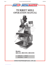
Control Panel & Motor Wiring
1NC
2
4
3NO
3NO
4
1NC
2
V3
V2
V1
1
2
6
6
2
2
3
0
12
13
Direction Switch
ON Button
Stop Button
Power
Lamp
Speed
Dial
Digital RPM
Readout
Control Panel
(viewed from behind)
2
1
Motor Wiring
Junction Box
3
Figure 1. Control panel wiring (viewed from behind).
Figure 2. Motor wiring.
To Electrical Panel (Page 33)
To Electrical
Panel
(Page 33)

MODEL G0678
VARIABLE SPEED 8" x 30"
VERTICAL MILL
OWNER'S MANUAL
COPYRIGHT © SEPTEMBER, 2008 BY GRIZZLY INDUSTRIAL, INC., REVISED OCTOBER, 2010 (TS)
WARNING: NO PORTION OF THIS MANUAL MAY BE REPRODUCED IN ANY SHAPE
OR FORM WITHOUT THE WRITTEN APPROVAL OF GRIZZLY INDUSTRIAL, INC.
(FOR MODELS MANUFACTURED SINCE 9/10) #TS10934 PRINTED IN TAIWAN

This manual provides critical safety instructions on the proper setup,
operation, maintenance, and service of this machine/tool. Save this
document, refer to it often, and use it to instruct other operators.
Failure to read, understand and follow the instructions in this manual
may result in fire or serious personal injury—including amputation,
electrocution, or death.
The owner of this machine/tool is solely responsible for its safe use.
This responsibility includes but is not limited to proper installation in
a safe environment, personnel training and usage authorization,
proper inspection and maintenance, manual availability and compre-
hension, application of safety devices, cutting/sanding/grinding tool
integrity, and the usage of personal protective equipment.
The manufacturer will not be held liable for injury or property damage
from negligence, improper training, machine modifications or misuse.
Some dust created by power sanding, sawing, grinding, drilling, and
other construction activities contains chemicals known to the State
of California to cause cancer, birth defects or other reproductive
harm. Some examples of these chemicals are:
• Lead from lead-based paints.
• Crystalline silica from bricks, cement and other masonry products.
• Arsenic and chromium from chemically-treated lumber.
Your risk from these exposures varies, depending on how often you
do this type of work. To reduce your exposure to these chemicals:
Work in a well ventilated area, and work with approved safety equip-
ment, such as those dust masks that are specially designed to filter
out microscopic particles.

Table of Contents
SECTION 5: ACCESSORIES ......................... 23
SECTION 6: MAINTENANCE ......................... 25
Schedule ...................................................... 25
Cleaning & Protecting .................................. 25
Lubrication ................................................... 25
V-Belt Tensioning......................................... 27
SECTION 7: SERVICE ................................... 28
Troubleshooting ........................................... 28
Adjusting Gibs .............................................. 30
Adjusting Backlash....................................... 31
SECTION 8: ELECTRICAL ............................ 32
Electrical Safety Instructions ........................ 32
Electrical Panel Wiring ................................. 33
Control Panel & Motor Wiring ...................... 34
SECTION 9: PARTS ....................................... 35
Head ............................................................ 35
Drive System................................................ 37
Table & Saddle ............................................ 38
Knee & Base ................................................ 39
Label Placement .......................................... 41
WARRANTY AND RETURNS ........................ 45
INTRODUCTION ............................................... 2
Foreword ........................................................ 2
Contact Info.................................................... 2
Functional Overview ...................................... 2
Identification ................................................... 3
Machine Data Sheet ...................................... 4
SECTION 1: SAFETY ....................................... 6
Safety Instructions for Machinery .................. 6
Additional Safety Instructions For Mills .......... 8
SECTION 2: CIRCUIT REQUIREMENTS ........ 9
220V Operation .............................................. 9
SECTION 3: SETUP ....................................... 10
Setup Safety ................................................ 10
Items Needed for Setup ............................... 10
Unpacking .................................................... 10
Inventory ...................................................... 11
Clean Up ...................................................... 11
Site Considerations ...................................... 12
Moving & Placing Base Unit ........................ 12
Mounting to Shop Floor ............................... 13
Assembly ..................................................... 14
Test Run ...................................................... 14
Spindle Break-In .......................................... 15
SECTION 4: OPERATIONS ........................... 16
Operation Safety .......................................... 16
Basic Controls .............................................. 16
Table Movement .......................................... 17
Head Rotation .............................................. 18
Turret Rotation ............................................. 19
Setting Spindle Speed ................................. 20
Downfeed Controls ...................................... 21
Loading/Unloading Tooling .......................... 22

-2-
Model G0678 (Mfg. since 9/10)
INTRODUCTION
Foreword
We are proud to offer the Model G0678 VS 8" x
30" Vertical Mill. This machine is part of a grow-
ing Grizzly family of fine metalworking machinery.
When used according to the guidelines set forth in
this manual, you can expect years of trouble-free,
enjoyable operation and proof of Grizzly’s com-
mitment to customer satisfaction.
The specifications, drawings, and photographs
illustrated in this manual represent the Model
G0678 when the manual was prepared. However,
owing to Grizzly’s policy of continuous improve-
ment, changes may be made at any time with no
obligation on the part of Grizzly. For your conve-
nience, we always keep current Grizzly manuals
available on our website at www.grizzly.com.
Any updates to your machine will be reflected
in these manuals as soon as they are complete.
Visit our site often to check for the latest updates
to this manual!
We stand behind our machines. If you have any
service questions, parts requests or general ques-
tions about the machine, please call or write us at
the location listed below.
Grizzly Industrial, Inc.
1203 Lycoming Mall Circle
Muncy, PA 17756
Phone: (570) 546-9663
Fax: (800) 438-5901
E-Mail: [email protected]
If you have any comments regarding this manual,
please write to us at the address below:
Grizzly Industrial, Inc.
C
/O Technical Documentation Manager
P.O. Box 2069
Bellingham, WA 98227-2069
Email: [email protected]
Contact Info
The Model G0678 vertical mill is used to remove
material from metal workpieces to form complex
shapes. Tooling is inserted into the spindle, which
can positioned in nearly any orientation above the
table and workpiece.
During most operations, the workpiece is clamped
to the table, then it is moved into the rotating cut-
ter in any combination of three paths—longitudi-
nal (X-axis), cross (Y-axis), and vertical (Z-axis).
The range of movement for the table is greater
than that of the head and spindle. However some
operations, such as drilling or tapping, are better
accomplished with vertical quill (spindle) move-
ment, using the coarse or fine downfeed con-
trols.
This mill uses a frequency drive to convert incom-
ing 220V single-phase power to 220V 3-phase
for efficient performance from the spindle motor.
Power is transferred directly to the spindle from
the motor by a V-belt and pulleys.
Spindle speed is electronically controlled by using
the variable speed dial and readout on the control
panel.
Functional Overview

Model G0678 (Mfg. since 9/10)
-3-
Figure 1. Model G0678 identification.
Identification
Front
Rear
A
B
C
N
O
P
Q
R
S
E
F
G
H
I
J
K
L
M
D
A. Control Panel (refer to Page 16 for details)
B. Coarse Downfeed Handle
C. V-Belt Cover
D. Motor 1
1
⁄2 HP, 220V, 3-Phase
E. Turret
F. Downfeed Selector
G. Work Light 110V
H. Longitudinal (X-Axis) Handwheel
I. Vertical (Z-Axis) Crank Handle
J. One-Shot Oiler
K. Base
L. Splash Pan
M. Column
N. V-Belt Tension Adjustment Bolt
O. Longitudinal Handwheel
P. Cross (Y-Axis) Feed Limit Stop Track
Q. Cross Feed Handwheel
R. Longitudinal Limit Stop Track
S. Fine Downfeed Handwheel

-4-
Model G0678 (Mfg. since 9/10)
The information contained herein is deemed accurate as of 11/25/2013 and represents our most recent product specifications.
Due to our ongoing improvement efforts, this information may not accurately describe items previously purchased.
PAGE 1 OF 2Model G0678
MACHINE DATA
SHEET
Customer Service #: (570) 546-9663 · To Order Call: (800) 523-4777 · Fax #: (800) 438-5901
MODEL G0678 8" X 30" VARIABLE SPEED VERTICAL MILL
Product Dimensions:
Weight.............................................................................................................................................................. 991 lbs.
Width (side-to-side) x Depth (front-to-back) x Height............................................................... 40-1/2 x 42-3/4 x 67 in.
Footprint (Length x Width)............................................................................................................................ 19 x 26 in.
Space Required for Full Range of Movement (Width x Depth).................................................................... 68 x 45 in.
Shipping Dimensions:
Type.......................................................................................................................................................... Wood Crate
Content........................................................................................................................................................... Machine
Weight.............................................................................................................................................................. 966 lbs.
Length x Width x Height....................................................................................................................... 45 x 45 x 76 in.
Must Ship Upright................................................................................................................................................... Yes
Electrical:
Power Requirement........................................................................................................... 220V, Single-Phase, 60 Hz
Prewired Voltage.................................................................................................................................................. 220V
Full-Load Current Rating....................................................................................................................................... 3.3A
Minimum Circuit Size.............................................................................................................................................. 15A
Connection Type....................................................................................................................................... Cord & Plug
Power Cord Included............................................................................................................................................... No
Recommended Power Cord............................................................................... “S”-Type, 3-Wire, 16 AWG, 300 VAC
Plug Included........................................................................................................................................................... No
Recommended Plug Type..................................................................................................................................... 6-15
Switch Type............................................................................................ Control Panel w/Magnetic Switch Protection
Inverter Type............................................................................................................................. Yaskawa RM5G-2001
Inverter Size......................................................................................................................................................... 1 HP
Motors:
Main
Type........................................................................................................................................... TEFC Induction
Horsepower............................................................................................................................................. 1.5 HP
Phase.................................................................................................................................................... 3-Phase
Amps........................................................................................................................................................... 3.3A
Speed................................................................................................................................................ 1725 RPM
Power Transfer ............................................................................................................................... V-Belt Drive
Bearings..................................................................................................... Shielded & Permanently Lubricated
Machine Data Sheet
data sheet

Model G0678 (Mfg. since 9/10)
-5-
The information contained herein is deemed accurate as of 11/25/2013 and represents our most recent product specifications.
Due to our ongoing improvement efforts, this information may not accurately describe items previously purchased.
PAGE 2 OF 2Model G0678
Main Specifications:
Operation Info
Spindle Travel........................................................................................................................................ 3-1/2 in.
Max Distance Spindle to Column................................................................................................................. 7 in.
Max Distance Spindle to Table.................................................................................................................. 20 in.
Longitudinal Table Travel (X-Axis)............................................................................................................. 18 in.
Cross Table Travel (Y-Axis).................................................................................................................. 7-3/4 in.
Vertical Table Travel (Z-Axis).............................................................................................................. 17-3/4 in.
Turret or Column Swivel (Left /Right)................................................................................................... 360 deg.
Head Tilt (Left/Right).............................................................................................................................. 90 deg.
Drilling Capacity for Cast Iron...................................................................................................................... 1 in.
Drilling Capacity for Steel......................................................................................................................... 3/4 in.
End Milling Capacity.................................................................................................................................... 1 in.
Face Milling Capacity................................................................................................................................... 3 in.
Table Info
Table Length.............................................................................................................................................. 30 in.
Table Width.................................................................................................................................................. 8 in.
Table Thickness........................................................................................................................................... 2 in.
Number of T-Slots............................................................................................................................................ 3
T-Slot Size................................................................................................................................................ 1/2 in.
T-Slots Centers.................................................................................................................................... 2-3/16 in.
Spindle Info
Spindle Taper............................................................................................................................................... R-8
Number of Vertical Spindle Speeds...................................................................................................... Variable
Range of Vertical Spindle Speeds........................................................................................... 200 – 2250 RPM
Drawbar Thread Size............................................................................................................................. 7/16-20
Drawbar Length.................................................................................................................................... 12-3/8 in
Spindle Bearings....................................................................................................... Angular Contact Bearings
Construction
Spindle Housing/Quill....................................................................... Chrome-Plated & Precision-Ground Steel
Table................................................................................................... Hardened & Precision Ground Cast Iron
Head.................................................................................................................................................... Cast Iron
Column/Base....................................................................................................................................... Cast Iron
Base..................................................................................................................................................... Cast Iron
Paint..................................................................................................................................................... Urethane
Other Specifications:
Country Of Origin ............................................................................................................................................. Taiwan
Warranty ........................................................................................................................................................... 1 Year
Approximate Assembly & Setup Time .............................................................................................................. 1 Hour
Serial Number Location ..................................................................................................................... ID Label on Side
ISO 9001 Factory .................................................................................................................................................... No
CSA Certified .......................................................................................................................................................... No
Features:
One-Shot Lubrication
High Precision Ball Bearings
Bronze Nut on Longitudinal & Cross Feed Leadscrews
Variable Frequency Drive Speed Control
Hardened & Precision Ground Leadscrews
Runs on Single-Phase Power Using a 3-Phase Inverter
Work Light
7/16 in.

-6-
Model G0678 (Mfg. since 9/10)
ELECTRICAL EQUIPMENT INJURY RISKS. You
can be shocked, burned, or killed by touching live
electrical components or improperly grounded
machinery. To reduce this risk, only allow qualified
service personnel to do electrical installation or
repair work, and always disconnect power before
accessing or exposing electrical equipment.
DISCONNECT POWER FIRST.
Always discon-
nect machine from power supply BEFORE making
adjustments, changing tooling, or servicing machine.
This prevents an injury risk from unintended startup
or contact with live electrical components.
EYE PROTECTION. Always wear ANSI-approved
safety glasses or a face shield when operating or
observing machinery to reduce the risk of eye
injury or blindness from flying particles. Everyday
eyeglasses are not approved safety glasses.
OWNER’S MANUAL. Read and understand this
owner’s manual BEFORE using machine.
TRAINED OPERATORS ONLY. Untrained oper-
ators have a higher risk of being hurt or killed.
Only allow trained/supervised people to use this
machine. When machine is not being used, dis-
connect power, remove switch keys, or lock-out
machine to prevent unauthorized use—especially
around children. Make workshop kid proof!
DANGEROUS ENVIRONMENTS. Do not use
machinery in areas that are wet, cluttered, or have
poor lighting. Operating machinery in these areas
greatly increases the risk of accidents and injury.
MENTAL ALERTNESS REQUIRED. Full mental
alertness is required for safe operation of machin-
ery. Never operate under the influence of drugs or
alcohol, when tired, or when distracted.
For Your Own Safety, Read Instruction
Manual Before Operating This Machine
The purpose of safety symbols is to attract your attention to possible hazardous conditions.
This manual uses a series of symbols and signal words intended to convey the level of impor-
tance of the safety messages. The progression of symbols is described below. Remember that
safety messages by themselves do not eliminate danger and are not a substitute for proper
accident prevention measures. Always use common sense and good judgment.
Indicates a potentially hazardous situation which, if not avoided,
MAY result in minor or moderate injury. It may also be used to alert
against unsafe practices.
Indicates a potentially hazardous situation which, if not avoided,
COULD result in death or serious injury.
Indicates an imminently hazardous situation which, if not avoided,
WILL result in death or serious injury.
This symbol is used to alert the user to useful information about
proper operation of the machine.
NOTICE
Safety Instructions for Machinery
SECTION 1: SAFETY

Model G0678 (Mfg. since 9/10)
-7-
WEARING PROPER APPAREL. Do not wear
clothing, apparel or jewelry that can become
entangled in moving parts. Always tie back or
coverlonghair.Wearnon-slipfootwear toavoid
accidentalslips,whichcouldcauselossofwork-
piececontrol.
hAzARdOus dusT. Dust created while using
machinery may cause cancer, birth defects, or
long-term respiratory damage. Beaware ofdust
hazardsassociatedwitheachworkpiecematerial,
andalwayswearaNIOSH-approvedrespiratorto
reduceyourrisk.
hEARING PROTECTION. Always wear hear-
ing protection when operating or observing loud
machinery. Extended exposure to this noise
withouthearingprotectioncan cause permanent
hearingloss.
REMOVE AdJusTING TOOLs. Tools left on
machinery can become dangerous projectiles
uponstartup.Neverleavechuckkeys,wrenches,
or any other tools on machine. Always verify
removalbeforestarting!
INTENdEd usAGE. Only use machine for its
intendedpurposeandnevermakemodifications
not approved by Grizzly. Modifying machine or
using it differently than intended may result in
malfunctionormechanicalfailurethatcanleadto
seriouspersonalinjuryordeath!
AWKWARd POsITIONs. Keep proper footing
andbalanceatalltimeswhenoperatingmachine.
Donotoverreach!Avoidawkwardhandpositions
that make workpiece control difficult or increase
the
riskofaccidentalinjury.
ChILdREN & BYsTANdERs. Keepchildrenand
bystandersatasafedistancefromtheworkarea.
Stopusingmachineiftheybecomeadistraction.
GuARds & COVERs.Guardsandcoversreduce
accidental contact with moving parts or flying
debris. Make sure they are properly installed,
undamaged,andworkingcorrectly.
FORCING MAChINERY.Donotforcemachine.
Itwill do the job safer andbetter at therate for
whichitwasdesigned.
NEVER sTANd ON MAChINE. Serious injury
may occur if machine is tipped or if the cutting
toolisunintentionallycontacted.
sTABLE MAChINE. Unexpectedmovementdur-
ing operation greatly increases risk of injury or
lossofcontrol.Beforestarting,verifymachineis
stableandmobilebase(ifused)islocked.
usE RECOMMENdEd ACCEssORIEs.Consult
thisowner’smanualorthemanufacturerforrec-
ommended accessories. Using improper acces-
sorieswillincreasetheriskofseriousinjury.
uNATTENdEd OPERATION. To reduce the
risk of accidental injury, turn machine off and
ensure all moving parts completely stop before
walking away. Never leave machine running
whileunattended.
MAINTAIN WITh CARE.Followallmaintenance
instructions and lubrication schedules to keep
machine in good working condition. A machine
that is
improperly maintained could malfunction,
leadingtoseriouspersonalinjuryordeath.
ChECK dAMAGEd PARTs. Regularly inspect
machine for any condition that may affect safe
operation.Immediatelyrepairorreplacedamaged
ormis-adjustedpartsbeforeoperatingmachine.
MAINTAIN POWER CORds. When disconnect-
ing cord-connected machines from power, grab
andpulltheplug—NOTthecord.Pullingthecord
may damage the wires inside. Do not handle
cord/plugwithwethands.Avoidcorddamageby
keepingitawayfromheatedsurfaces,hightraffic
areas,harshchemicals,andwet/damplocations.
EXPERIENCING dIFFICuLTIEs. If at any time
youexperiencedifficultiesperformingtheintend-
edoperation,stopusingthemachine!Contactour
TechnicalSupportat(570)546-9663.

-8-
Model G0678 (Mfg. since 9/10)
Additional Safety Instructions For Mills
1. UNDERSTANDING CONTROLS. Make
sure you understand the use and operation
of all controls.
2. SAFETY ACCESSORIES. Always use a
chip guard in addition to your safety glasses
or use a face shield when milling to reduce
the risk of injury from flying chips.
3. WORK HOLDING. Before starting the
machine, be certain the workpiece has been
properly clamped to the table. NEVER hold
the workpiece by hand during operation.
4. CHUCK KEY SAFETY. Always remove
chuck key, drawbar wrench, and any service
tools immediately after use and before start-
ing the mill.
5. SPINDLE SPEEDS. Select the spindle
speed that is appropriate for the type of
work and material. Allow the mill to reach full
speed before beginning a cut.
6. POWER DISRUPTION. In the event of a
local power outage during operation, turn
OFF all switches to avoid possible sudden
start up once power is restored.
7. STOPPING SPINDLE. DO NOT stop the
spindle using your hand. Allow the spindle to
stop on its own, or, in the case of an emer-
gency, use the spindle brake.
8. CLEAN-UP. DO NOT clear chips by hand
or compressed air. Use a brush or vacuum,
and never clear chips while the spindle is
turning.
9. BE ATTENTIVE. DO NOT leave mill run-
ning unattended for any reason.
10. MACHINE CARE AND MAINTENANCE.
Never operate the mill with damaged or
worn parts. Maintain your mill in proper
working condition. Perform routine inspec-
tions and maintenance promptly. Put away
adjustment tools after use.
11. DISCONNECT POWER. Make sure the mill
is turned OFF, disconnected from its power
source and all moving parts have come to a
complete stop before changing cutting tools,
starting any inspection, adjustment, or main-
tenance procedure.
12. AVOIDING ENTANGLEMENT. DO NOT
wear loose clothing, gloves, or jewelry when
operating mill. Tie back long hair and roll up
sleeves.
13. TOOL HOLDING. Always use the proper
tools for your operation. Make sure tools are
held firmly in place.
14. CUTTING TOOL INSPECTION. Inspect
drills and end mills for sharpness, chips,
or cracks before each use. Replace dull,
chipped, or cracked cutting tools immedi-
ately. Handle new cutting tools with care.
Leading edges are very sharp and can
cause lacerations.
15. SPINDLE DIRECTION CHANGES. Never
reverse spindle direction while the spindle is
in motion.
16. EXPERIENCING DIFFICULTIES. If at any
time you are experiencing difficulties per-
forming the intended operation, stop using
the machine! Contact our Technical Support
at (570) 546-9663.
Like all machinery there is potential danger when operating this mill. Accidents are frequently
caused by lack of familiarity or failure to pay attention. Use this mill with respect and caution to
reduce the risk of operator injury. If normal safety precautions are overlooked or ignored, serious
personal injury may occur.

Model G0678 (Mfg. since 9/10)
-9-
220V Single-Phase
Operation
Full Load Amperage Draw
This machine draws the following amps under
maximum load:
Amp Draw .............................................3.3 Amps
Power Supply Circuit Requirements
You MUST connect your machine to a grounded
circuit that is rated for the amperage given below.
Never replace a circuit breaker on an existing cir-
cuit with one of higher amperage without consult-
ing a qualified electrician to ensure compliance
with wiring codes. If you are unsure about the
wiring codes in your area or you plan to con-
nect your machine to a shared circuit, consult
a qualified electrician.
Minimum Circuit Size ............................. 15 Amps
Extension Cords
Using extension cords may reduce the life of the
motor. Instead, place the machine near a power
source. If you must use an extension cord:
• Use at least a 16 gauge cord that does not
exceed 50 feet in length!
• The extension cord must also have a ground
wire and plug pin.
• A qualified electrician MUST size cords over
50 feet long to prevent motor damage.
SECTION 2: CIRCUIT REQUIREMENTS
Serious personal injury could occur if you
connect the machine to power before com-
pleting the setup process. DO NOT connect
the machine to the power until instructed
later in this manual.
Electrocution or fire could
result if machine is not
grounded and installed in
compliance with electrical
codes. Compliance MUST
be verified by a qualified
electrician!
Power Connection Device
The type of plug required to connect your machine
to power depends on the type of service you cur-
rently have or plan to install. We recommend
using the plug shown in Figure 2.
Grounding Prong
Current Carrying Prongs
6-15 PLUG
GROUNDED
6-15 RECEPTACLE
Figure 2. NEMA 6-15 plug and receptacle.
NOTICE
The Model G0678 uses a 1 HP Yasakawa
frequency drive to convert incoming single-
phase power to 3-phase for greater spindle
motor performance.

-10-
Model G0678 (Mfg. since 9/10)
Wear safety glasses dur-
ing the entire setup pro-
cess!
This machine presents
serious injury hazards
to untrained users. Read
through this entire manu-
al to become familiar with
the controls and opera-
tions before starting the
machine!
Setup Safety
SECTION 3: SETUP
Your machine was carefully packaged for safe
transportation. Remove the packaging materials
from around your machine and inspect it. If you
discover the machine is damaged, please imme-
diately call Customer Service at (570) 546-9663
for advice.
Save the containers and all packing materials for
possible inspection by the carrier or its agent.
Otherwise, filing a freight claim can be difficult.
When you are completely satisfied with the condi-
tion of your shipment, inventory the contents.
Unpacking
The Model G0678 is a
heavy machine. Serious
personal injury may
occur if safe moving
methods are not used.
To be safe, get assis-
tance and use power
equipment rated for at
least 1500 lbs. to move
the shipping crate and
remove the machine
from the crate.
The following items are needed to complete the
setup process, but are not included with your
machine:
Description Qty
• Assistants ................................................... 2
• Precision Level ........................................... 1
• Hex Wrench 4mm ....................................... 1
• External Retaining Ring Pliers ................... 1
• Safety Glasses ........................ 1 Per Person
• Lifting Straps
(rated for at least 1500 lbs.) ........................ 2
• Power Lifting Equipment
(rated for at least 1500 lbs.) ........................ 1
• Machine Mounting Hardware ..... As Needed
• Cleaning Solvent & Rags ........... As Needed
Items Needed for
Setup

Model G0678 (Mfg. since 9/10)
-11-
Inventory
The following is a description of the main compo-
nents shipped with your machine. Lay the compo-
nents out to inventory them.
Note: If you can't find an item on this list, check
the mounting location on the machine or examine
the packaging materials carefully. Occasionally
we pre-install certain components for shipping
purposes.
Inventory: (Figure 3) Qty
A. Cap Screws M6-1 x 25 ............................... 3
B. Handwheel Handles ................................... 3
C. Hex Wrench 5mm ....................................... 1
D. Hex Wrench 4mm ....................................... 1
If any nonproprietary parts are missing (e.g. a
nut or a washer), we will gladly replace them; or
for the sake of expediency, replacements can be
obtained at your local hardware store.
SUFFOCATION HAZARD!
Immediately discard all plas-
tic bags and packing materi-
als to eliminate choking/suf-
focation hazards for children
and animals.
Figure 3. Model G0678 inventory.
A
B
D
C
The unpainted surfaces are coated with a waxy
oil to prevent corrosion during shipment. Remove
this protective coating with a solvent cleaner or
degreaser, such as shown in Figure 4. For thor-
ough cleaning, some parts must be removed.
For optimum performance, clean all moving
parts or sliding contact surfaces. Avoid chlo-
rine-based solvents, such as acetone or brake
parts cleaner that may damage painted surfac-
es. Always follow the manufacturer’s instructions
when using any type of cleaning product.
Clean Up
Gasoline and petroleum
products have low flash
points and can explode
or cause fire if used to
clean machinery. DO
NOT use these products
to clean the machinery.
Many cleaning solvents
are toxic if inhaled.
Minimize your risk by only
using these products in a
well ventilated area.
G2544—Solvent Cleaner & Degreaser
H9692—Orange Power Degreaser
Great products for removing shipping grease.
Figure 4. Cleaner/degreasers available from
Grizzly.

-12-
Model G0678 (Mfg. since 9/10)
Floor Load
Refer to the Machine Data Sheet on Page 4 for
the weight and footprint specifications of your
machine. Some residential floors may require
additional reinforcement to support both the
machine and operator.
Placement Location
Consider existing and anticipated needs, size of
material to be processed through each machine,
and space for auxiliary stands, work tables or
other machinery when establishing a location for
your new machine. See Figure 5 for the minimum
working clearances.
Children and visitors may be
seriously injured if unsuper-
vised around this machine.
Lock entrances to the shop
or disable start switch or
power connection to prevent
unsupervised use.
Site Considerations
Figure 5. Minimum working clearances.
45"
68"
Moving & Placing
Base Unit
The Model G0678 is a
heavy machine. Serious
personal injury may
occur if safe moving
methods are not used.
To be safe, get assis-
tance and use power
equipment rated for at
least 1500 lbs. to move
the shipping crate and
remove the machine
from the crate.
To move and place your mill:
1. After removing the crate from the shipping
pallet, wrap lifting straps around the turret, as
shown in Figure 6, and securely attach them
to your power lifting equipment.
Figure 6. Positioning the lifting straps.
Turret
Lifting Straps

Model G0678 (Mfg. since 9/10)
-13-
Although not required, we recommend that you
mount your new machine to the floor. Because
this is an optional step and floor materials may
vary, floor mounting hardware is not included.
Generally, you can either bolt your machine to
the floor or mount it on machine mounts. Both
options are described below. Whichever option
you choose, it is necessary to level your machine
with a precision level.
Mounting to Shop
Floor
NOTICE
Anchor studs are stronger and more per-
manent alternatives to lag shield anchors;
however, they will stick out of the floor,
which may cause a tripping hazard if you
decide to move your machine.
Figure 8. Machine mount example.
Using Machine Mounts
Using machine mounts, shown in Figure 8, gives
the advantage of fast leveling and vibration reduc-
tion. The large size of the foot pads distributes
the weight of the machine to reduce strain on the
floor.
NOTICE
We strongly recommend securing your
machine to the floor if it is hardwired to the
power source. Consult with your electrician
to ensure compliance with local codes.
2. Use a
1
⁄2" wrench to unbolt the mill from the
pallet.
3. With assistance to steady the machine, lift
it just enough to clear the pallet and floor
obstacles, then move it to the prepared loca-
tion.
4. When mounting the machine to the floor, use
a precision level to make sure the table is
level from side-to-side and front-to-back.
Note: If necessary, use shims to make sure
there are no gaps between the base and the
floor to avoid cracking or warping the cast
iron.
Bolting to Concrete Floors
Anchor studs and lag shield anchors with lag
bolts (see Figure 7) are two popular methods for
anchoring an object to a concrete floor. We sug-
gest you research the many options and methods
for mounting your machine and choose the best
that fits your specific application.
Figure 7. Typical fasteners for mounting to
concrete floors.
Anchor Stud
Lag Shield Anchor & Bolt

-14-
Model G0678 (Mfg. since 9/10)
Assembly
To assemble your mill:
1. Secure the three handles to the handwheels
with the M6-1 x 25 cap screws, as shown in
Figure 9.
2. Use the external retaining ring pliers to
remove the retaining ring from the end of
the vertical crank screw, reverse the crank
handle, then re-install the retaining ring (see
Figure 10).
Before starting the mill, make sure you
have performed the preceding assembly
instructions, and you have read through the
rest of the manual and are familiar with the
various functions and safety features on
this machine. Failure to follow this warning
could result in serious personal injury or
even death!
Test Run
Once the assembly is complete, test run your
machine to make sure it runs properly and is
ready for regular operation. The test run consists
of verifying the following: 1) The motor powers up
and runs correctly and 2) the stop button safety
feature works correctly.
If, during the test run, you cannot easily locate
the source of an unusual noise or vibration, stop
using the machine immediately, then review
Troubleshooting on Page 28.
If you cannot find a remedy, contact our Tech
Support at (570) 546-9663 for assistance.
To test run the machine:
1. Make sure you understand the safety instruc-
tions at the beginning of the manual and that
the machine is set up properly.
2. Make sure all tools and objects used during
setup are cleared away from the machine.
3. Make sure the machine is lubricated (refer to
Lubrication on Page 25 for detailed instruc-
tions).
4. Refer to Basic Controls on Page 16 to
become familiar with the control panel func-
tions.
5 . Connect the machine to the power source—
the power lamp on the control panel should
light.
Figure 9. Handle attached to handwheel.
Handle
Figure 10. Vertical crank handle properly
installed.
Retaining Ring

Model G0678 (Mfg. since 9/10)
-15-
7. Verify that the machine is operating correctly
by pushing the ON button.
—When operating correctly, the machine
runs smoothly with little or no vibration or
rubbing noises.
— Investigate and correct strange or unusual
noises or vibrations before operating the
machine further. Always disconnect the
machine from power when investigating or
correcting potential problems.
8. With the machine still running, use the speed
dial to decrease/increase the spindle speed.
9. Press the stop button to stop the machine.
10. WITHOUT resetting the switch, press the ON
button. The machine should not start.
—If the machine does not start, the stop but-
ton safety feature is working correctly. The
Test Run is complete.
—If the machine does start (with the stop
button pushed in), immediately disconnect
power to the machine. The stop button
safety feature is not working correctly. This
safety feature must work properly before
proceeding with regular operations. Call
Tech Support for help.
When all of the Test Run procedures are success-
fully completed, proceed to Spindle Break-In.
Figure 11. Resetting the switch.
6. Push the stop button in, then twist it clock-
wise so it pops out. When the stop button
pops out, the switch is reset and ready for
operation (see Figure 11).
Spindle Break-In
NOTICE
Successfully complete the spindle break-in
procedure to avoid rapid wear of spindle
components when placed into operation.
It is essential to closely follow the proper break-in
procedures to ensure trouble-free performance of
your mill.
To perform the spindle break-in procedure:
1. Turn the machine ON, then use the speed
dial to adjust the spindle speed to approxi-
mately 200 RPM.
2. Let the mill run at this speed for 20 minutes,
then turn the spindle OFF and wait for it to
stop.
3. Use the spindle direction switch on the con-
trol panel to reverse the spindle direction,
then turn the mill ON and let it run for another
20 minutes.
4. Set the spindle speed at approximately 1800
RPM, then repeat Steps 2–3.
5. Turn the mill OFF. The spindle break-in is
now complete and the machine is ready for
operation.
/