Page is loading ...

U39 Gas Stove
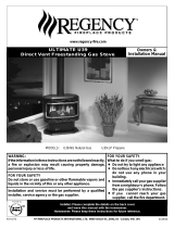
U39 Top Vent Freestanding Direct Vent Gas Stove
A
C
D
B
E
3/8" NPT
gas line in
F
G
H
mobile home
mounting holes
on bottom pedestal
I
Model U39-NG1 U39-LP1
Fuel Type Natural Gas Propane
Minimum Supply Pressure 5” W.C. (1.25 kPa) 12” W.C. (3.00 kPa)
Manifold Pressure - High 3.8” W.C. (0.94 kPa) 11” W.C. (2.74 kPa)
Manifold Pressure - Low 1.1” W.C. (0.27 kPa) 2.9” W.C. (0.72 kPa)
Orifi ce Size
Altitude 0-2000ft (0-610m) #31
#50
Orifi ce Size Altitude 2000-4500ft (610-1370m) #33
Orifi ce Size
30,000 Max BTU #37 #52
Minimum Input
Altitude 0-2000ft (0-610m) 20,000 BTU/h
20,000 BTU/h
Minimum Input Altitude 2000-4500ft (610-1370m) 19,000 BTU/h
Minimum Input
Converted to 30,000 Max BTU 15,000 BTU/h 15,000 BTU/h
Maximum Input Altitude 0-2000ft (0-610m) 38,000 BTU/h
38,000 BTU/h
Maximum Input Altitude 2000-4500ft (610-1370m) 36,100 BTU/h
Maximum Input Converted to 30,000 Max BTU 30,000 BTU/h 30,000 BTU/h
Vent Sizing 4” Inner / 6-5/8” Outer 4” Inner / 6-5/8” Outer
J
K
L
M
J
N
O
O
N
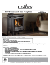
Alcove clearances
Dimension Description U38
J Side Wall to Unit 7-1/2” (190mm)
K Back Wall to Unit 6” (155mm)
L Back Wall to vent centerline 11” (280mm)
M Side Wall to Vent Centerline 20-1/2” (521mm)
Corner Clearances
Dimension Description U38
N Wall to Unit corner 2” (50mm)
O Wall to vent centerline 11” (280mm)
Minimum ceiling height is 36" (914mm) from top of unit.
Minimum clearance to vent is 1-1/4” (32mm).
The above listed clearances are minimum distances to combustible
materials. When installing on carpet or vinyl fl ooring the bottom pedestal
cover plate must be installed.
Dimension Description U39
A Top Width 26” (660mm)
B Unit Height 30” (762mm)
C Top Depth (back to front face) 17-5/8” (448mm)
D Top Depth 17” (432mm)
E Height; Base to Gas Line 3-1/2” (89mm)
F Base Depth 17” (432mm)
G Depth; Flue-Centerline to Back 3-1/2” (89mm)
H Width; Side of unit to Gas Line 10-3/4” (273mm)
I Width - Mobile Home Mounting 13” (330mm)
Approved Venting Systems
Flex Vent Systems: FPI AstroCap™ Flex Vent
Rigid Pipe Vent Systems: Simpson Dura-Vent® Direct Vent GS
American Metal Products Ameri Vent
Security Secure Vent®
Selkirk Direct-Temp.
157June 2007 Regency Product Specifi cations Book
Gas Stoves
Gas Stoves

4 ft. Pipe Length
with Kit # 946-216
or 2 ft. Pipe Length with
Kit # 946-116
Adapter
Trim Collar
Trim
Collar
4" ID Liner
Spacer
Spring
Adjustable Pipe
Length 13-1/2" - 24",
2 pieces
90 Elbow
o
Thimble
Cover
AstroCap
Termination Cap
(Part# 946-523/P)
Wall Thimble
(only required
in Canada)
Vent Restrictor Position
To set the Vent restriction as indicated in the diagram, simply loosen
the screws and push the vent restrictor plate to the correct position.
Tighten the screws.
Vent Restrictor setting at 38,000 Btu/h
Vent Restrictor setting at 30,000 Btu/h
U39 Gas Stove
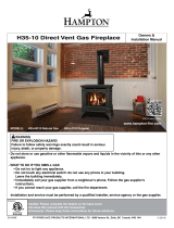
Regency Direct Vent System
Horizontal Terminations Only
These venting systems, in combination with the U39 Direct Vent Gas
Fireplace, have been tested and listed as a direct vent heater system
by Warnock Hersey. The location of the termination cap must conform
to the requirements in the Vent Terminal Locations diagram.
FPI Horizontal Termination Kit includes all the necessary parts
needed to install the U39.
FPI Kit # Length Contains:
#946-116 2 Feet 1) 6-5/8” Rigid Pipe Section (Kit length)
2) 4” fl exible liner (Kit length)
3) spring spacers (4)
4) 90° Elbow
5) Adjustable pipe section 13-1/2” to 24”
6) thimble cover (1)
7) thimble (1)
8) adapter
9) AstroCap termination cap (1)
10) trim collar (2)
11) tube of Mill Pac (1)
12) S.S. screws #8 x 1-1/2”, self-tap, (12)
13) Blk. screws #8 x 1-1/2”, self-tap, (14)
14) Blk. screws #8 x 1-1/2” drill point, (4)
15) S.S. screws #8 x 1-1/2” drill point, (4)
16) Wood screws #8 x 1” (8)
17) vinyl siding standoff
(optional #946-206)
#946-216 4 Feet
Notes:
1) Liner sections should be continuous without any joints or seams.
2) Only Flex pipe purchased from Regency may be used for Flex
installations.
3) Horizontal sections must be supported every 3 feet.
If required by the external termination location the listed
alternate termination caps may be used. (Refer to Page 11)
Alternate Horizontal
Termination Caps
Alternate:
Horizontal
Riser Vent
Terminal
Part# 640-530/P
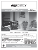
Pipe Length
Vertical
Termination
Cap
Storm Collar
Flashing
Ceiling Firestop
Pipe
Length
Adj.Pipe Length
11" - 14-5/8"
90 Elbow
o
Horizontal
Termination Cap
(Part # 946-523/P)
Wall Thimble
(only required
in Canada)
Vinyl Siding
Standoff (Optional)
Rigid Pipe Venting Systems
Horizontal or Vertical Terminations
Alternate Horizontal
Termination Caps
Alternate:
Horizontal
Riser Vent
Terminal
Part# 640-530/P
158 June 2007 Regency Product Specifi cations Book
Gas Stoves
Gas Stoves

U39 Gas Stove
Vertical Terminations using Rigid
Pipe Systems
The shaded area in the diagram below shows all allowable combinations
of straight vertical and offset to vertical runs with vertical terminations.
Maximum two 45º elbows.
If the vent is ENCLOSED in a chase (min. size 9" x 9") maintain a 1-1/4"
clearance to combustibles.
May be installed in Manufactured (Mobile) Homes after fi rst sale.
Vertical Venting with Two (2) 90° Elbows
Two 45° elbows = One 90° elbow
Option V H V+ V1 Maximum total pipe length, of
all sections, must not exceed
30 feet.
Total horizontal sections must
not exceed 4 feet.
Minimum of 1 foot between
90° elbows is required.
A) 1’ Min. 1’ Max. 2’ Min.
B) 1’ Min. 2’ Max. 3’ Min.
C) 2’ Min. 3’ Max. 4’ Min.
D) 2’ Min. 4’ Max. 4’ Min.
Vent Restrictor in position “A” (Center), refer to page 124.
159June 2007 Regency Product Specifi cations Book
Gas Stoves
Gas Stoves

Horizontal Terminations for All
Venting Systems
The shaded areas in the diagram below show all allowable combinations
of vertical runs with horizontal terminations. Maximum one 90° elbow
(two 45º
elbows equal one 90° elbow).
Propane and Natural Gas:
Residential, Manufactured and Mobile Homes
Installations
The venting arrangements diagrammed below, have a min. of 75%
(fl ue loss) effi ciency with Fan Off, as required for manufactured homes.
(Actual effi ciency may be as high as 85%)
May be installed in Manufactured (Mobile) Homes after fi rst sale.
U39 Gas Stove
Horizontal Venting with Two (2) 90°
Elbows
Two 45° elbows = One 90° elbow
Option V H + H1 Maximum total pipe length, of all
sections, must not exceed 30 feet.
Total horizontal sections must not
exceed 4 feet.
Minimum of 1 foot between 90°
elbows is required.
A) 3’ Min. 2’ Max.
B) 5’ Min. 3’ Max.
C) 8’ Min. 4’ Max.
Vent Restrictor in position “A” (Center), refer to page 124.
160 June 2007 Regency Product Specifi cations Book
Gas Stoves
Gas Stoves
/