
MPM3610
21V Input, 1.2A Module
Synchronous Step-Down Converter
with Integrated Inductor
MPM3610 Rev. 1.01 www.MonolithicPower.com 1
1/7/2015 MPS Proprietary Information. Patent Protected. Unauthorized Photocopy and Duplication Prohibited.
© 2015 MPS. All Rights Reserved.
The Future of Analog IC Technology
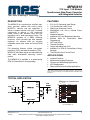
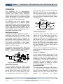
DESCRIPTION
The MPM3610 is a synchronous, rectified, step-
down converter module with built-in power
MOSFETs, inductor, and two capacitors. It
offers a compact solution with only 5 external
components to achieve a 1.2A continuous
output current with excellent load and line
regulation over a wide input-supply range. The
MPM3610 operates at a 2MHz switching
frequency, which provides fast load transient
response. An external AAM pin provides
selectable power-save mode and forced PWM
mode.
Full protection features include over-current
protection (OCP) and thermal shutdown (TSD).
MPM3610 eliminates design and manufacturing
risks while dramatically improving time-to-
market.
The MPM3610 is available in a space-saving
QFN-20 (3mmx5mmx1.6mm) package.
FEATURES
4.5V to 21V Operating Input Range
1.2A Continuous Load Current
200A Low Quiescent Current
90m/40m Low RDS(ON) Internal Power
MOSFETs
Integrated Inductor
Integrated VCC and Bootstrap Capacitors
External AAM for Power-Save Mode
Programming
OCP with Hiccup
Thermal Shutdown
Output Adjustable from 0.8V
Available in a QFN-20 (3mmx5mmx1.6mm)
Package
Total Solution Size 6.7mmx6.3mm
APPLICATIONS
Industrial Controls
Medical and Imaging Equipment
Telecom and Networking Applications
LDO Replacement
Space and Resource-Limited Applications
All MPS parts are lead-free and adhere to the RoHS directive. For MPS green
status, please visit MPS website under “Quality Assurance”. “MPS” and “The
Future of Analog IC Technology” are registered trademarks of Monolithic Powe
r
Systems, Inc.
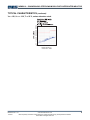
TYPICAL APPLICATION
50
55
60
65
70
75
80
85
90
95
100
LOAD CURRENT (A)
0.01 0.1 1 10
Efficiency vs. Load Current
V
OUT
=3.3V
V
IN
=19V
V
IN
=5V
V
IN
=12V

MPM3610 – SYNCHRONOUS STEP-DOWN MODULE WITH INTEGRATED INDUCTOR
MPM3610 Rev. 1.01 www.MonolithicPower.com 2
1/7/2015 MPS Proprietary Information. Patent Protected. Unauthorized Photocopy and Duplication Prohibited.
© 2015 MPS. All Rights Reserved.
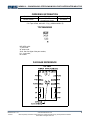
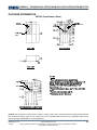
ORDERING INFORMATION
Part Number* Package Top Marking
MPM3610GQV QFN-20
(3mmx5mmx1.6mm) See Below
* For Tape & Reel, add suffix –Z (e.g. MPM3610GQV–Z)
TOP MARKING
MP: MPS prefix:
Y: year code;
W: week code:
3610: first four digits of the part number;
LLL: lot number;
M: module
PACKAGE REFERENCE

MPM3610 – SYNCHRONOUS STEP-DOWN MODULE WITH INTEGRATED INDUCTOR
MPM3610 Rev. 1.01 www.MonolithicPower.com 3
1/7/2015 MPS Proprietary Information. Patent Protected. Unauthorized Photocopy and Duplication Prohibited.
© 2015 MPS. All Rights Reserved.
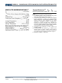
ABSOLUTE MAXIMUM RATINGS (1)
VIN ..................................................-0.3V to 28V
VSW ......................................................................
-0.3V (-5V for <10ns) to 28V (30V for <10ns)
VBST ........................................................ VSW+6V
All Other Pins................................-0.3V to 6V (2)
Continuous Power Dissipation (TA = +25°C) (3)
............................................................. 2.7W
Junction Temperature...............................150°C
Lead Temperature ....................................260°C
Storage Temperature................. -65°C to 150°C
Recommended Operating Conditions (4)
Supply Voltage VIN ...........................4.5V to 21V
Output Voltage VOUT.............. 0.8V to VIN*DMAX (5)
Operating Junction Temp. (TJ). -40°C to +125°C
Thermal Resistance (6) θJA θJC
QFN-20 (3mmx5mmx1.6mm) . 46 ...... 10... °C/W
Notes:
1) Exceeding these ratings may damage the device.
2) For additional details on EN pin’s ABS MAX rating, please
refer to the “Enable Control” section on page 14.
3) The maximum power dissipation is a function of the maximum
junction temperature TJ (MAX), the junction-to-ambient
thermal resistance JA, and the ambient temperature TA. The
maximum continuous power dissipation at any ambient
temperature is calculated by PD (MAX) = (TJ (MAX)-TA)/JA.
Exceeding the maximum allowable power dissipation will
produce an excessive die temperature, causing the converte
r
to go into thermal shutdown. Internal thermal shutdown
circuitry protects the device from permanent damage.
4) The device is not guaranteed to function outside of its
operating conditions.
5) In practical design, the minimum VOUT is limited by the
minimum on-time. To allow a margin, a 50ns on-time is
recommended for calculating. To set the output voltage above
5.5V, please refer to the application information on page 17.
6) Measured on JESD51-7, 4-layer PCB.

MPM3610 – SYNCHRONOUS STEP-DOWN MODULE WITH INTEGRATED INDUCTOR
MPM3610 Rev. 1.01 www.MonolithicPower.com 4
1/7/2015 MPS Proprietary Information. Patent Protected. Unauthorized Photocopy and Duplication Prohibited.
© 2015 MPS. All Rights Reserved.
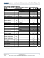
ELECTRICAL CHARACTERISTICS
Vin=12V, TJ=-40°C to +125°C(7), typical value is tested at TJ=+25°C, unless otherwise noted.
Parameter Symbol Condition Min Typ Max Units
Supply Current (Shutdown) IIN VEN = 0V, TJ=+25°C 1
A
VFB = 1V, VAAM=0.5V 0.2
Supply Current (Quiescent) Iq VFB = 1V, VAAM=5V 0.7
mA
HS Switch-On Resistance HSRDS-ON VBST-SW=5V 90 m
LS Switch-On Resistance LSRDS-ON VCC =5V 40 m
Integrated Inductor Inductance(8) L 1 µH
Inductor DC Resistance LDCR T
J=+25°C 42 60 80 m
Switch Leakage SWLKG V
EN = 0V, VSW =12V 1 A
Current Limit (8) I
LIMIT Under 40% Duty Cycle 2.4 3 A
VFB=0.75V, TJ=+25°C 1700 2000 2400 kHz
Oscillator Frequency fSW VFB=0.75V,TJ=-40°C to +125°C 1500 2000 2500 kHz
Fold-Back Frequency fFB V
FB<400mV 0.3 fSW
Maximum Duty Cycle DMAX V
FB=700mV 80 85 %
Minimum On Time(8) ON_MIN 35 ns
TJ=+25°C 786 798 810 mV
Feedback Voltage VFB TJ=-40°C to +125°C 782 798 814 mV
Feedback Current IFB V
FB=820mV 10 50 nA
TJ=+25°C 5.6 6.2 6.8 A
AAM Source Current IAAM TJ=-40°C to +125°C 4.3 6.2 7.9 A
EN Rising Threshold VEN_RISING 1.15 1.4 1.65 V
EN Falling Threshold VEN_FALLIN
G 1.05 1.25 1.45 V
EN Input Current IEN VEN=2V 2 A
VIN Under-Voltage Lockout
Threshold—Rising INUVVth 3.65 3.9 4.15 V
VIN Under-Voltage Lockout
Threshold—Hysteresis INUVHYS 650 mV
VCC Regulator VCC 4.9 V
VCC Load Regulation ICC=5mA 1.5 %
Soft-Start Time tSS Vo from 10% to 90% 1.5 ms
Thermal Shutdown (8) 150 °C
Thermal Hysteresis (8) 20 °C
Notes:
7) Not tested in production; guaranteed by over-temperature correlation.
8) Guaranteed by characterization test.

MPM3610 – SYNCHRONOUS STEP-DOWN MODULE WITH INTEGRATED INDUCTOR
MPM3610 Rev. 1.01 www.MonolithicPower.com 5
1/7/2015 MPS Proprietary Information. Patent Protected. Unauthorized Photocopy and Duplication Prohibited.
© 2015 MPS. All Rights Reserved.
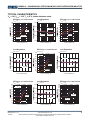
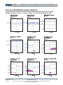
TYPICAL CHARACTERISTICS
VIN = 12V, VOUT = 3.3V, TA = 25°C, unless otherwise noted.
LOAD CURRENT (A)
LOAD CURRENT (A)
Load Regulation
V
OUT
=5V
Load Regulation
V
OUT
=2.5V
Load Regulation
V
OUT
=3.3V
Load Regulation
V
OUT
=1.8V
LOAD CURRENT (A)
LOAD CURRENT (A)
30
35
40
45
50
55
60
65
70
75
80
85
90
95
100
50
55
60
65
70
75
80
85
90
95
100
50
55
60
65
70
75
80
85
90
95
100
50
55
60
65
70
75
80
85
90
95
100
50
55
60
65
70
75
80
85
90
95
100
LOAD CURRENT (A)
Efficiency vs. Load Current
V
OUT
=5V
0.01 0.1 1 10
LOAD CURRENT (A)
Efficiency vs. Load Current
V
OUT
=2.5V
0.01 0.1 1 10
LOAD CURRENT (A)
0.01 0.1 1 10
LOAD CURRENT (A)
Efficiency vs. Load Current
V
OUT
=1.8V
0.01 0.1 1 10
LOAD CURRENT (A)
Efficiency vs. Load Current
V
OUT
=1.2V
0.01 0.1 1 10
Efficiency vs. Load Current
V
OUT
=3.3V
V
IN
=8V
V
IN
=12V
V
IN
=19V
V
IN
=5V
V
IN
=12V
V
IN
=19V
V
IN
=5V
V
IN
=12V
V
IN
=19V
-0.40
-0.20
0.00
0.20
0.40
0 0.4 0.8 1.2
V
IN
=8V
V
IN
=19V
V
IN
=12V
-0.40
-0.20
0.00
0.20
0.40
01
V
IN
=5V
V
IN
=19V
V
IN
=12V
-0.40
-0.20
0.00
0.20
0.40
01
V
IN
=5V
V
IN
=19V
V
IN
=12V
-0.40
-0.20
0.00
0.20
0.40
01
V
IN
=12V
V
IN
=19V
V
IN
=5V
V
IN
=19V
V
IN
=5V
V
IN
=12V
V
IN
=12V
V
IN
=5V

MPM3610 – SYNCHRONOUS STEP-DOWN MODULE WITH INTEGRATED INDUCTOR
MPM3610 Rev. 1.01 www.MonolithicPower.com 6
1/7/2015 MPS Proprietary Information. Patent Protected. Unauthorized Photocopy and Duplication Prohibited.
© 2015 MPS. All Rights Reserved.
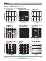
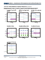
TYPICAL CHARACTERISTICS
(continued)
VIN = 12V, VOUT = 3.3V, TA = 25°C, unless otherwise noted.
0
2
4
6
8
10
12
14
16
18
20
0
5
10
15
20
25
30
35
40
45
2
2.2
2.4
2.6
2.8
3
3.2
3.4
3.6
3.8
0 20406080100
0 5 10 15 20 25 0 0.5 1 1.5
30
35
40
45
50
55
60
65
70
75
80
85
90
95
100
0.01 0.1 1 10
-1.0
-0.8
-0.6
-0.4
-0.2
0.0
0.2
0.4
0.6
0.8
1.0
01
0 0.5 1 1.5
-0.40
-0.20
0.00
0.20
0.40
01 -0.40
-0.20
0.00
0.20
0.40
-60
-40
-20
0
20
40
60
1,000 10,000 100,000 1,000,000
-180
-120
-60
0
60
120
180
10
12
14
16
18
20
22
0.8 1.3 1.8 2.3 2.8 3.3 3.8 4.3 4.8 5.3

MPM3610 – SYNCHRONOUS STEP-DOWN MODULE WITH INTEGRATED INDUCTOR
MPM3610 Rev. 1.01 www.MonolithicPower.com 7
1/7/2015 MPS Proprietary Information. Patent Protected. Unauthorized Photocopy and Duplication Prohibited.
© 2015 MPS. All Rights Reserved.
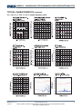
TYPICAL CHARACTERISTICS
(continued)
VIN = 12V, VOUT = 3.3V, TA = 25°C, unless otherwise noted.
2
2.2
2.4
2.6
2.8
3
3.2
3.4
3.6
3.8
4
2
2.5
3
3.5
4
4.5
5
-40 -20 0 20 40 60 80 100 120140
1
1.1
1.2
1.3
1.4
1.5
1.6
-40 -20 0 20 40 60 80 100 120 140
1700
1800
1900
2000
2100
2200
2400
2300
-40 -20 0 20 40 60 80 100120 140 -40 -20 0 20 40 60 80 100 120 140
-40 -20 0 20 40 60 80 100 120 140
0.7
0.72
0.74
0.76
0.78
0.8
0.82
0.84
0.86
0.88
0.9
10
12
14
16
18
20
22
24
26
28
30
12 13 14 15 16 17 18 19 20 21
4.5 7.5 10.5 13.5 16.5 19.5
0
0.2
0.4
0.6
0.8
1
30M
-10
-5
0
5
10
15
20
25
30
35
40
45
50
55
60
65
70
50 60 80100M 200 300 400 600M150k
0
5
10
15
20
25
30
35
40
45
50
55
60
65
70
75
80
500 1M 2M 10M 30M

MPM3610 – SYNCHRONOUS STEP-DOWN MODULE WITH INTEGRATED INDUCTOR
MPM3610 Rev. 1.01 www.MonolithicPower.com 8
1/7/2015 MPS Proprietary Information. Patent Protected. Unauthorized Photocopy and Duplication Prohibited.
© 2015 MPS. All Rights Reserved.
TYPICAL CHARACTERISTICS
(continued)
VIN = 12V, VOUT = 3.3V, TA = 25°C, unless otherwise noted.
30M 50 60 80100M 200 300 400 600M
-10
-5
0
5
10
15
20
25
30
35
40
45
50
55
60
65
70

MPM3610 – SYNCHRONOUS STEP-DOWN MODULE WITH INTEGRATED INDUCTOR
MPM3610 Rev. 1.01 www.MonolithicPower.com 9
1/7/2015 MPS Proprietary Information. Patent Protected. Unauthorized Photocopy and Duplication Prohibited.
© 2015 MPS. All Rights Reserved.
TYPICAL PERFORMANCE CHARACTERISTICS
Performance waveforms are captured from the evaluation board discussed in the Design
Example section.VIN = 12V, VOUT = 3.3V, COUT=22µF, TA = 25°C, unless otherwise noted.
V
OUT
2V/div.
V
EN
5V/div.
V
SW
20V/div.
V
OUT
2V/div.
V
IN
10V/div.
V
SW
10V/div.
V
OUT
2V/div.
V
IN
10V/div.
V
SW
10V/div.
I
OUT
1A/div.
V
OUT
2V/div.
V
IN
5V/div.
V
SW
10V/div.
I
OUT
1A/div.
V
IN/
AC
50mV/div.
V
OUT/
AC
10mV/div.
V
SW
5V/div.
V
OUT
2V/div.
V
IN
5V/div.
V
SW
10V/div.
V
IN/
AC
50mV/div.
V
OUT/
AC
20mV/div.
V
SW
5V/div.
V
OUT
/AC
10mV/div.
V
OUT
/AC
10mV/div.

MPM3610 – SYNCHRONOUS STEP-DOWN MODULE WITH INTEGRATED INDUCTOR
MPM3610 Rev. 1.01 www.MonolithicPower.com 10
1/7/2015 MPS Proprietary Information. Patent Protected. Unauthorized Photocopy and Duplication Prohibited.
© 2015 MPS. All Rights Reserved.
TYPICAL PERFORMANCE CHARACTERISTICS
(continued)
Performance waveforms are captured from the evaluation board discussed in the Design
Example section.VIN = 12V, VOUT = 3.3V, COUT=22µF, TA = 25°C, unless otherwise noted.
V
OUT
2V/div.
V
EN
5V/div.
V
SW
20V/div.
V
OUT
2V/div.
V
EN
5V/div.
V
SW
5V/div.
I
OUT
2A/div.
V
OUT
2V/div.
V
EN
5V/div.
V
SW
20V/div.
I
OUT
1A/div.
V
OUT
2V/div.
V
SW
10V/div.
I
OUT
2A/div.
V
OUT
2V/div.
V
SW
10V/div.
I
OUT
5A/div.
V
OUT
2V/div.
V
SW
10V/div.
I
OUT
5A/div.
V
OUT
/AC
50mV/div.
I
OUT
500mA/div.

MPM3610 – SYNCHRONOUS STEP-DOWN MODULE WITH INTEGRATED INDUCTOR
MPM3610 Rev. 1.01 www.MonolithicPower.com 11
1/7/2015 MPS Proprietary Information. Patent Protected. Unauthorized Photocopy and Duplication Prohibited.
© 2015 MPS. All Rights Reserved.
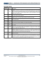
PIN FUNCTIONS
Package
Pin # Name Description
1 FB
Feedback. Connect FB to the tap of an external resistor divider from the output to
AGND to set the output voltage. To prevent current-limit runaway during a short-circuit
fault, the frequency foldback comparator lowers the oscillator frequency when the FB
voltage is below 400mV. Place the resistor divider as close as possible to FB. Avoid
placing vias on the FB traces.
2 VCC
Internal 4.9V LDO Output. The module integrates a LDO output capacitor, so there is
no need to add an external capacitor.
3 AGND
Analog Ground. Reference ground of logic circuit. AGND is connected internally to
PGND, so there is no need to add any external connections to PGND.
4, 5, 6 SW Switch Output. A large copper plane is recommended on pins 4, 5, and 6 to improve
thermal performance.
7, 8, 9 OUT Power Output. Connect load to OUT. An output capacitor is needed.
10, 15, 19,
20 NC No Connection. DO NOT CONNECT. NC must be left floating.
11 BST
Bootstrap. A bootstrap capacitor is integrated internally, so an external connection is
not needed.
12, 13, 14 PGND
Power Ground. Reference ground of the power device. PCB layout requires extra care
(please see recommended “PCB Layout Guidelines” on page 19). For best results,
connect to PGND with copper and vias.
16 IN
Supply Voltage. IN supplies power for the internal MOSFET and regulator. The
MPM3610 operates from a +4.5V to +21V input rail. It requires a low ESR and low-
inductance capacitor to decouple the input rail. Place the input capacitor very close to
IN and connect it with wide PCB traces and multiple vias.
17 EN
Enable. EN=high to enable the module. Leave EN floating or connect it to GND to
disable the module.
18 AAM
Advanced Asynchronous Modulation. AAM sources a 6.2A current from an internal
4.9V supply. Float AAM or drive AAM high (>2.5V) to force the MPM3610 to operate in
continuous conduction mode (CCM). If AAM mode is required under light load, connect
a resistor to ground to program AAM voltage in the range of 0V to1V.

MPM3610 – SYNCHRONOUS STEP-DOWN MODULE WITH INTEGRATED INDUCTOR
MPM3610 Rev. 1.01 www.MonolithicPower.com 12
1/7/2015 MPS Proprietary Information. Patent Protected. Unauthorized Photocopy and Duplication Prohibited.
© 2015 MPS. All Rights Reserved.
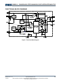
FUNCTIONAL BLOCK DIAGRAM
Figure 1. Functional Block Diagram

MPM3610 – SYNCHRONOUS STEP-DOWN MODULE WITH INTEGRATED INDUCTOR
MPM3610 Rev. 1.01 www.MonolithicPower.com 13
1/7/2015 MPS Proprietary Information. Patent Protected. Unauthorized Photocopy and Duplication Prohibited.
© 2015 MPS. All Rights Reserved.
OPERATION
The MPM3610 is a high-frequency,
synchronous, rectified, step-down, switch-mode
converter with built-in power MOSFETs,
inductor, and two capacitors. It offers a compact
solution that achieves a 1.2A continuous output
current with excellent load and line regulation
over a 4.5V to 21V input-supply range.
The MPM3610 has three working modes:
advanced asynchronous modulation (AAM),
similar to PFM mode, discontinuous conduction
mode (DCM), and continuous conduction mode
(CCM). The load current increases as the
device transitions from AAM mode to DCM to
CCM. If AAM is floated or pulled high (>2.5V),
the MPM3610 operates in CCM.
AAM Control Operation
In a light-load condition, MPM3610 operates in
AAM mode (see Figure 2). Connect a resistor
from AAM to GND to set VAAM. VCOMP is the
error-amplifier output, which represents the
peak inductor current information. When VCOMP
is lower than VAAM, the internal clock is blocked.
This causes the MPM3610 to skip pulses,
achieving the light-load power save. Refer to
AN032 for additional details.
The internal clock re-sets every time VCOMP
exceeds VAAM. Simultaneously, the high-side
MOSFET (HS-FET) turns on and remains on
until VILsense reaches the value set by VCOMP.
Figure 2. Simplified AAM Control Logic
DCM Control Operation
The VCOMP ramps up as the output current
increases. When its minimum value exceeds
VAAM, the device enters DCM. In this mode the
internal 2MHz clock initiates the PWM cycle,
the HS-FET turns on and remains on until
VILsense reaches the value set by VCOMP (after a
period of dead time), and then the low-side
MOSFET (LS-FET) turns on and remains on
until the inductor-current value decreases to
zero. The device repeats the same operation in
every clock cycle to regulate the output voltage
(see Figure 3).
Figure 3. DCM Control Operation
CCM Control Operation
The device enters CCM from DCM once the
inductor current no longer drops to zero in a
clock cycle. In CCM, the internal 2MHz clock
initiates the PWM cycle, the HS-FET turns on
and remains on until VILsense reaches the value
set by VCOMP (after a period of dead time), and
then the LS-FET turns on and remains on until
the next clock cycle starts. The device repeats
the same operation in every clock cycle to
regulate the output voltage.
If VILsense does not reach the value set by VCOMP
within 85% of one PWM period, the HS-FET will
be forced off.
Internal VCC Regulator
A 4.9V internal regulator powers most of the
internal circuitries. This regulator takes VIN and
operates in the full VIN range. When VIN
exceeds 4.9V, the output of the regulator is in
full regulation. If VIN is less than 4.9V, the output
decreases. The device integrates an internal
decoupling capacitor, so adding an external
VCC output capacitor is unnecessary.
Error Amplifier (EA)
The error amplifier compares the FB voltage to
the internal 0.798V reference (VREF) and
outputs a current proportional to the difference
between the two. This output current then
charges or discharges the internal

MPM3610 – SYNCHRONOUS STEP-DOWN MODULE WITH INTEGRATED INDUCTOR
MPM3610 Rev. 1.01 www.MonolithicPower.com 14
1/7/2015 MPS Proprietary Information. Patent Protected. Unauthorized Photocopy and Duplication Prohibited.
© 2015 MPS. All Rights Reserved.
compensation network to form the COMP
voltage; the COMP voltage controls the power
MOSFET current. The optimized, internal
compensation network minimizes the external
component count and simplifies control loop
design.
Under-Voltage Lockout (UVLO)
Under-voltage lockout (UVLO) protects the chip
from operating at an insufficient input-supply
voltage. The MPM3610 UVLO comparator
monitors the output voltage of the internal
regulator (VCC). The UVLO rising threshold is
about 3.9V while its falling threshold is 3.25V.
Enable Control (EN)
EN turns the converter on and off. Drive EN
high to turn on the converter; drive EN low to
turn off the converter. An internal 1M resistor
from EN to GND allows EN to be floated to shut
down the chip.
EN is clamped internally using a 6.5V series-
Zener-diode (see Figure 4).
Figure 4. 6.5V Zener Diode Connection
Connecting EN to a voltage source directly
without a pull-up resistor requires limiting the
amplitude of the voltage source to 6V to
prevent damage to the Zener diode.
Connecting the EN input through a pull-up
resistor to the voltage on the VIN pin limits the
EN input current to less than 100µA.
For example, with 12V connected to Vin,
RPULLUP (12V – 6.5V) ÷ 100µA = 55k.
Internal Soft-Start (SS)
Soft-start prevents the converter output voltage
from overshooting during start-up. When the
chip starts up, the internal circuitry generates a
soft-start voltage (SS) that ramps up from 0V to
4.9V. When SS is lower than VREF (0.798V), the
error amplifier uses SS as the reference. When
SS is higher than VREF, the error amplifier uses
VREF as the reference. The SS time is set
internally to 1.5ms (VOUT from 10% to 90%).
Pre-Bias Start-Up
The MPM3610 is designed for a monotonic
start-up into a pre-biased output voltage. If the
output is pre-biased to a certain voltage during
start-up, the voltage on the soft-start capacitor
is charged. When the soft-start capacitor’s
voltage exceeds the sensed output voltage at
FB, the device turns on the HS-FET and the
LS-FET sequentially. Output voltage ramps up
following the soft-start slew rate.
Over-Current Protection (OCP) and Hiccup
The MPM3610 has a cycle-by-cycle over-
current limiting control. When the inductor
current-peak value exceeds the internal peak
current-limit threshold, the HS-FET turns off
and the LS-FET turns on, remaining on until the
inductor current falls below the internal valley
current-limit threshold. The valley current-limit
circuit is employed to decrease the operation
frequency (after the peak current-limit threshold
is triggered). Meanwhile, the output voltage
drops until VFB is below the under-voltage (UV)
threshold (50% below the reference, typically).
Once UV is triggered, the MPM3610 enters
hiccup mode to re-start the part periodically.
This protection mode is useful when the output
is dead-shorted to ground and greatly reduces
the average short-circuit current to alleviate
thermal issues and protect the converter. The
MPM3610 exits hiccup mode once the over-
current condition is removed.
Thermal Shutdown (TSD)
To prevent thermal damage, MPM3610 stops
switching when the die temperature exceeds
150°C. As soon as the temperature drops
below its lower threshold (130°C, typically), the
power supply resumes operation.
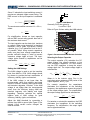
Floating Driver and Bootstrap Charging
An internal bootstrap capacitor powers the
floating power MOSFET driver. This floating
driver has its own UVLO protection. The
UVLO’s rising threshold is 2.2V with a
hysteresis of 150mV. The bootstrap capacitor
voltage is regulated internally by VIN through D1,
M1, C4, L1, and C2 (see Figure 5). If (VBST-VSW)

MPM3610 – SYNCHRONOUS STEP-DOWN MODULE WITH INTEGRATED INDUCTOR
MPM3610 Rev. 1.01 www.MonolithicPower.com 15
1/7/2015 MPS Proprietary Information. Patent Protected. Unauthorized Photocopy and Duplication Prohibited.
© 2015 MPS. All Rights Reserved.
exceeds 5V, U1 regulates M1 to maintain a 5V
voltage across C4.
Figure 5. Internal Bootstrap Charging Circuit
Start-Up and Shutdown
If both VIN and VEN exceed their respective
thresholds, the chip starts up. The reference
block starts first, generating stable reference
voltage, and then the internal regulator is
enabled. The regulator provides a stable supply
for the remaining circuitries.
Three events shut down the chip: VIN low, VEN
low, and thermal shutdown. During the
shutdown procedure, the signaling path is
blocked first to avoid any fault triggering. The
COMP voltage and the internal supply rail are
then pulled down. The floating driver is not
subject to this shutdown command.
Additional RC Snubber Circuit
An additional RC snubber circuit can be chosen
to clamp the voltage spike and damp the ringing
voltage for better EMI performance.
The power dissipation of the RC snubber circuit
is estimated by the formula below:
2
Loss S S IN
PfCV
Where fS is the switching frequency, Cs is the
snubber capacitor, and VIN is the input voltage.
For improved efficiency, the value of CS should
not be set too high. Generally, a 5.6 RS and a
330pF CS are recommended to generate the
RC snubber circuit (see Figure 6).
Figure 6. Additional RC Snubber Circuit

MPM3610 – SYNCHRONOUS STEP-DOWN MODULE WITH INTEGRATED INDUCTOR
MPM3610 Rev. 1.01 www.MonolithicPower.com 16
1/7/2015 MPS Proprietary Information. Patent Protected. Unauthorized Photocopy and Duplication Prohibited.
© 2015 MPS. All Rights Reserved.
APPLICATION INFORMATION
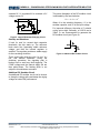
Setting the Output Voltage
The external resistor divider sets the output
voltage (see “Typical Application” on page 1).
Choose R1 (refer to Table 1); R2 is then given
by:
OUT
R1
R2 V1
0.798V
Figure 7. Feedback Network
See Table 1 and Figure 7 for the feedback
network and a list of recommended feedback
network parameters for common output
voltages.
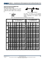
Table 1. Recommended Parameters for Common Output Voltages
Small Solution Size(CIN=10µF,
COUT=22µF/0805/16V)
Low VOUT Ripple(CIN=10µF,
COUT=2X22µF/0805/16V)
VIN
(V)
VOUT
(V)
RAAM
(k)
R1
(k)
R2
(k)
VOUT
PFM
Ripple
(mV)(9)
VOUT
PWM
Ripple
(mV)(10)
Load
Transient
(mV)(11)
R1
(k)
R2
(k)
VOUT
PFM
Ripple
(mV) (9)
VOUT
PWM
Ripple
(mV) (10)
Load
Transient
(mV) (11)
5 30 100 19.1 49 17.6 89 40.2 7.68 18.6 9.4 56
3.3 22.6 102 32.4 53 12.4 64 62 19.6 21 7 45
21
2.5 14.7 120 56.2 42.6 10 57 62 29.4 21.6 5.2 34
5 33 100 19.1 44.2 16.4 91 40.2 7.68 18 8.8 58
3.3 25.5 102 32.4 49 11.4 67 62 19.6 19.2 6.6 46
19
2.5 20 120 56.2 51.2 9.8 58 62 29.4 24.4 5 36
5 41.2 100 19.1 45.2 15.6 92 40.2 7.68 17.8 7.8 59
3.3 30 102 32.4 42.2 10.6 69 62 19.6 15.8 6 49
2.5 24.3 120 56.2 52.6 9.6 62 62 29.4 21.8 4.8 39
16
1.8 14.7 120 95.3 40.2 8.6 49 75 59 19.8 4 34
5 46.4 100 19.1 34 14.8 92 40.2 7.68 17.6 7.4 60
3.3 33 102 32.4 35.4 10.2 71 40.2 12.7 13.8 5.6 41
2.5 28 102 47.5 43.8 9.4 59 62 29.4 21.6 4.6 42
1.8 21 120 95.3 46.6 8.4 53 75 59 22 4.2 36
14
1.5(12) 16.9 158 180 44 7.2 56 100 113 21.2 3.6 38
5 53.6 100 19.1 49.8 13.8 93 34 6.49 14.2 6.4 57
3.3 39 75 24 27.4 9.4 61 40.2 12.7 14 5.2 40
2.5 32.4 102 47.5 35.8 9 62 62 29.4 18 4.4 44
1.8 25.5 102 82 39.4 7.8 50 75 59 20.2 4 39
1.5(12) 20 158 180 41.8 6.6 61 82 93.1 18.4 3.4 36
12
1.2(12) 16.2 191 383 35 6.2 65 120 240 17.8 3 43

MPM3610 – SYNCHRONOUS STEP-DOWN MODULE WITH INTEGRATED INDUCTOR
MPM3610 Rev. 1.01 www.MonolithicPower.com 17
1/7/2015 MPS Proprietary Information. Patent Protected. Unauthorized Photocopy and Duplication Prohibited.
© 2015 MPS. All Rights Reserved.
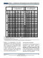
Table 1. Recommended Parameters For Common Output Voltages(continued)
Small Solution Size(CIN=10µF,
COUT=22µF/0805/16V)
Low VOUT Ripple(CIN=10µF,
COUT=2X22µF/0805/16V)
VIN
(V)
VOUT
(V)
RAAM
(k)
R1
(k)
R2
(k)
VOUT
PFM
Ripple
(mV) (9)
VOUT
PWM
Ripple
(mV) (10)
Load
Transient
(mV) (11)
R1
(k)
R2
(k)
VOUT
PFM
Ripple
(mV) (9)
VOUT
PWM
Ripple
(mV) (10)
Load
Transient
(mV) (11)
5 60.4 100 19.1 39.4 13.2 91 34 6.49 17.8 6.2 57
3.3 48.7 75 24 27.8 8.4 59 40.2 12.7 12.8 4.8 41
2.5 41.2 102 47.5 43.4 8.2 63 62 29.4 21.4 4 45
1.8 31.6 102 82 37 7.2 53 75 59 21.6 3.6 42
1.5 27.4 120 137 40.2 6 54 75 84.5 18.2 3.2 41
1.2(12) 22.6 191 383 38.6 5.4 70 82 162 19.8 2.8 37
10
1(12) 18.7 191 750 36.6 4.8 68 120 470 19.2 2.6 46
5 73.2 100 19.1 39.6 9.2 88 34 6.49 21.4 5 58
3.3 62 75 24 37.4 7.6 58 40.2 12.7 26.4 3.8 42
2.5 51 102 47.5 40.6 7 64 62 29.4 21.6 3.4 46
1.8 38.3 102 82 36.6 6.4 56 75 59 21.4 3 45
1.5 34 120 137 33.8 5.4 57 75 84.5 20.6 2.8 41
1.2(12) 29.4 158 316 33.4 5 67 82 162 18.2 2.6 40
8
1(12) 23.7 158 620 30.6 4.6 63 100 402 17.4 2.2 44
3.3 82.5 75 24 27.8 6 57 40.2 12.7 13.6 3.4 41
2.5 69.8 102 47.5 36.6 5.8 62 62 29.4 20 3.2 46
1.8 52.3 102 82 32.6 5.2 57 75 59 18.8 2.8 47
1.5 45.3 120 137 28.6 5 61 75 84.5 17 2.4 44
1.2(12) 41.2 120 237 30.6 4.6 60 82 162 18.6 2.2 44
5
1(12) 36.5 120 470 27 4.4 56 82 324 17 2 40
Notes:
9) VOUT PFM ripple is tested when Io=0A, for those specs noted (12), the ripple is tested when Io=1mA.
10) VOUT PWM ripple is tested when Io=1.2A.
11) Load transient from 0.6A to 1.2A, slew rate =0.8A/µs.
12) In these specs, BST operation current will charge the output voltage higher than the setting value when there is completely no load, due to
a large divider resistor value. A 10µA load current can pull the output voltage to a normal regulation level.
Normally, it is recommended to set output
voltage from 0.8V to 5.5V. However, it can be set
larger than 5.5V. In this case, the output-voltage
ripple is larger due to a larger inductor-ripple
current. An additional output capacitor is needed
to reduce the output-ripple voltage.
If output voltage is high, heat dissipation
becomes more important. Please refer to the
“PCB Layout Guidelines” section on page 19 to
achieve better thermal performance.
Selecting the Input Capacitor
The input current to the step-down converter is
discontinuous, and therefore requires a
capacitor to supply the AC current while
maintaining the DC input voltage. Use low ESR
capacitors for improved performance. Use
ceramic capacitors with X5R or X7R dielectrics
for optimum results because of their low ESR
and small temperature coefficients. For most
applications, use a 10µF capacitor.

MPM3610 – SYNCHRONOUS STEP-DOWN MODULE WITH INTEGRATED INDUCTOR
MPM3610 Rev. 1.01 www.MonolithicPower.com 18
1/7/2015 MPS Proprietary Information. Patent Protected. Unauthorized Photocopy and Duplication Prohibited.
© 2015 MPS. All Rights Reserved.
Since C1 absorbs the input-switching current, it
requires an adequate ripple-current rating. The
RMS current in the input capacitor is estimated
by:
IN
OUT
IN
OUT
LOAD1C V
V
1
V
V
II
The worst case condition occurs at VIN = 2VOUT,
where:
2
I
ILOAD
1C
For simplification, choose an input capacitor
with an RMS current rating greater than half of
the maximum load current.
The input capacitor can be electrolytic, tantalum,
or ceramic. When using electrolytic or tantalum
capacitors, add a small, high-quality ceramic
capacitor (e.g. 0.1F) placed as close to the IC
as possible. When using ceramic capacitors,
make sure they have enough capacitance to
provide sufficient charge in order to prevent
excessive voltage ripple at input. The input-
voltage ripple caused by capacitance can be
estimated as:
LOAD OUT OUT
IN IN
SIN
IV V
V1
fC1V V
Setting the AAM Voltage
The AAM voltage is used to set the transition
point from AAM to CCM. AAM voltage should
be chosen to provide the best combination of
efficiency, stability, ripple, and transient.
If the AAM voltage is set lower than the
recommended value, then stability and ripple
improve, however, efficiency during AAM mode
and transient degrades. Likewise, if the AAM
voltage is set higher than the recommended
value, then the efficiency during AAM and
transient improves, with stability and ripple
degrading. Therefore calculate the optimal
balance point of AAM voltage for good
efficiency, stability, ripple, and transient.
Adjust the AAM threshold by connecting a
resistor from AAM to ground (see Figure 8). An
internal 6.2µA current source charges the
external resistor.
Figure 8. AAM Network
Generally, R4 is then given by:
VAAM=R4 x 6.2µA
Refer to Figure 9 when setting the AAM resistor.
Figure 9. Recommended AAM Resistor Selection
Selecting the Output Capacitor
The output capacitor (C2) maintains the DC
output voltage. Use ceramic, tantalum, or low
ESR electrolytic capacitors. For best results,
use low ESR capacitors to keep the output-
voltage ripple low. The output-voltage ripple is
estimated as:
OUT OUT
OUT ESR
S1 IN S
VV 1
V1R
fL V 8fC2
Where L1 is the inductor value, RESR is the
equivalent series resistance (ESR) value of the
output capacitor, and L1=1H.
For ceramic capacitors, the capacitance
dominates the impedance at the switching
frequency; the capacitance causes the majority
of the output-voltage ripple. For simplification,
the output-voltage ripple can be estimated as:
OUT OUT
OUT 2
IN
S1
VV
V1
V
8f L C2
For tantalum or electrolytic capacitors, the ESR
dominates the impedance at the switching
frequency. For simplification, the output ripple
can be approximated as:

MPM3610 – SYNCHRONOUS STEP-DOWN MODULE WITH INTEGRATED INDUCTOR
MPM3610 Rev. 1.01 www.MonolithicPower.com 19
1/7/2015 MPS Proprietary Information. Patent Protected. Unauthorized Photocopy and Duplication Prohibited.
© 2015 MPS. All Rights Reserved.
OUT OUT
OUT ESR
IN
S1
VV
V1R
fL V
The characteristics of the output capacitor
affect the stability of the regulation system. The
MPM3610 internal compensation is optimized
for a wide range of capacitance and ESR
values.
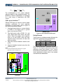
PCB Layout Guidelines (13)
Efficient PCB layout is critical to achieve stable
operation, particularly for input capacitor
placement. For best results, refer to Figure 10
and follow the guidelines below:
1. Use large ground plane to connect directly
to PGND. If the bottom layer is ground
plane, add vias near PGND.
2. The high-current paths (PGND, IN, and
OUT) should have short, direct, and wide
traces. Place the ceramic input capacitor
close to IN and PGND. Keep the input
capacitor and IN connection as short and
wide as possible.
3. Place the external feedback resistors next
to FB.
4. Keep the feedback network away from the
switching node.
Notes:
13) The recommended layout is based on the “Typical
Application Circuits” on pages 21-23.
AGND
SW OUT
FB
VCC
NC
BST
NC
AAM
EN
IN
NC
PGND
C1
R2 R1
C2
PGND
VOUTGNDVIN
R3
6.3mm
6.7mm
PGND
NC
NC
Top Layer
VOUT
GND
Bottom Layer
Figure 10. Recommended PCB Layout
Design Example
Table 2 below is a design example following the
application guidelines for the specifications:
Table 2. Design Example
VIN 12V
VOUT 3.3V
Io 1.2A
The detailed application schematic is shown in
Figure 12. The typical performance and circuit
waveforms have been shown in the “Typical
Performance Characteristics” section. For more
device applications, please refer to the related
evaluation board datasheets.

MPM3610 – SYNCHRONOUS STEP-DOWN MODULE WITH INTEGRATED INDUCTOR
MPM3610 Rev. 1.01 www.MonolithicPower.com 20
1/7/2015 MPS Proprietary Information. Patent Protected. Unauthorized Photocopy and Duplication Prohibited.
© 2015 MPS. All Rights Reserved.
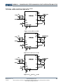
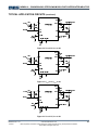
TYPICAL APPLICATION CIRCUITS (14)(15)
Figure 11. VOUT=5V, IOUT=1.2A
Figure 12. VOUT=3.3V, IOUT=1.2A
Figure 13. VOUT=2.5V, IOUT=1.2A
Page is loading ...
Page is loading ...
Page is loading ...
-
 1
1
-
 2
2
-
 3
3
-
 4
4
-
 5
5
-
 6
6
-
 7
7
-
 8
8
-
 9
9
-
 10
10
-
 11
11
-
 12
12
-
 13
13
-
 14
14
-
 15
15
-
 16
16
-
 17
17
-
 18
18
-
 19
19
-
 20
20
-
 21
21
-
 22
22
-
 23
23


