Page is loading ...

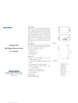
IT-IPS-215-IU-F-4-POE Series
4-Ports Poe + 1-Port Fast Ethernet
Industrial PoE Switch User Manual

- 1 -
【Summarize】
IT-IPS-215-IU-F-4-POE is an industrial grade, managed and redundancy PoE Ethernet switch, it support 5 Fast Ethernet ports. The 4 Fast Ethernet
port (1~4) support Power-over -Ethernet (PoE) function, another Fast Ethernet port is 10/100MBase-T(x) RJ45 or 100M Base-FX optic fiber. The
switches are classified as power source equipment (PSE), and when used in this way, the switch enable centralization of the power supply, providing
up to 30 watts of power per port and reducing the effort needed for installing power. The switches can be used to power IEEE802.3af/at standard
devices (PD), eliminating the need for additional wiring.
It support CE, FCC standard, the switch adopt industry standard design, IP40 protection, rugged high-strength metal case, power supply input
(48VDC). The switch support IEEE802.3/IEEE802.3u with 10/100M, full/half-duplex, and MDI/MDI-X auto-sensing, providing reliable and
economic solution for your industrial Ethernet network.
【Packing list】
The industrial PoE switch is shipped with the following items. If any of these items are missing or damaged, please contact your customer service
representative for assistance.
Industrial PoE switch ⅹ 1
User manual ⅹ 1
DIN-Rail mounting kit ⅹ 1
【Features】
Support 4 10/100Base-TX POE ports and 1 Fast Ethernet port
Support IEEE802.3, IEEE802.3u, IEEE802.3x, IEEE802.3af/at, store and forward
Support IEEE802.3af standard, full-port (PoE) full 15.4W power supply
Support IEEE802.3at standard, single-port maximum 30W power supply.
4 Fast Ethernet port (1~4) support POE function
Ethernet port support 10/100M self-adaption
DC48V power input, reverse connection protection
IP40 protect grade, high strength iron shell, DIN Rail installation
Industrial grade 4 design
【Panel layout】
Top and bottom panel view Rear panel view

- 2 -
Front view
1. Ground screw
2. Power input terminal block (3 bits)
3. DIP switches
4. DIN-Rail mounting kit
5. Power indicator
6. PoE state indicator
7. System running indicator
8. Link/ACT indicator
9. 10/100M Base-T(x) PoE port
10. 10/100M Base-T(x) port
11. 100M Base-FX optic fiber port
【Power supply input】
The product top panel provided 3 bit power supply input terminal block, support DC input. Voltage input (1, 3) range is 45~55VDC. The power
support is not polarity that the device can still work normally after the reverse.

- 3 -
【Dimensions】
The series of products are the same size, and the type of the Ethernet interface is different. Unit (mm)
4-port 10/100M Base-T(x) PoE + 1-port 10/100M Base-T(x):
4-port 10/100M Base-T(x) PoE + 1-port 00M Base-FX:
【DIP Switch】
Top panel provided 4 bits DIP switch to do function configure (ON to enable effective). 1 is RJ45 port support pause frame flow control and the
optic fiber port support back press flow control. 2 is force mode (RJ45 10M), but optic fiber port speed unchanged. 3 is VLAN function that port 5
with port 1-4 can communication, but between ports 1 to port 4 cannot communication. 4 is keeping for future function. Please power off and power
on when you change the status of DIP switch.

- 4 -
【Communication connector】
10/100BaseT(X) Ethernet port
The pinout define of RJ45 port display as below, connect by UTP or STP. The connect distance is no more than 100m. 100Mbps is used 120Ωof
UTP 5, 10Mbps is used 120Ωof UTP 3, 4, 5.
RJ45 port support automatic MDI/MDI-X operation. Can connect the PC, Server, Converter and HUB .Pin 1,2,3,6 Corresponding connection in
MDI. 1→3, 2→6, 3→1, 6→2 are used as cross wiring in the MDI-X port of Converter and HUB. 10Base-T/100Base-TX are used in MDI/MDI-X,
the define of Pin in the table as below.
NO.
MDI signal
MDI-X signal
1
TX+
RX+
2
TX-
RX-
3
RX+
TX+
6
RX-
TX-
4, 5, 7, 8
—
—
Note: “TX±” Transmit Data±, “RX±” Receive Data±, “—” Not use.
10/100Base-T(X) MDI (straight-through cable)
10/100Base-T(X) MDI-X (Cross over cable)
MDI/MDI-X auto connection makes switch easy to use for customers without considering the type of network cable.
1 8

- 5 -
100Base-FX Fiber port
100Base-FX full-duplex SM or MM port, SC/ST/FC type .The fiber port must be used in pair, TX (transmit) port connect remote switch’s RX
(receive) port; RX (receive) port connect remote switch’s TX (transmit) port.
The optical fiber connection supports the line to instruct enhance the reliability of network effectively.
Suppose: If you make your own cable, we suggest labeling the two sides of the same line with the same letter (A-to-A and B-to-B, shown as below,
or A1-to-A2 and B1-to-B2).
【LED Indicators】
LED indictor light on the front panel of product, the function of each LED is described in the table as below.
System indication LED
LED
State
Description
PWR
ON
Power is being supplied to power input PWR input
OFF
Power is not being supplied to power input PWR input
RUN
ON/OFF
System is not running well
Blinking
System is running well
Link/ACT
(1~5)
ON
Port connection is active
OFF
Port connection is not active
Blinking
Data transmitted
POE
(1~4)
ON
The PoE device is connected by IEEE802.3af/at standard
OFF
No PoE power output or no PoE
connected PoE devices
【Installation】
Before installation, confirm that the work environment meet the installation require, including the power needs and abundant space. Whether it is
close to the connection equipment and other equipments are prepared or not.
1. Avoid in the sunshine, keep away from the heat fountainhead or the area where in intense EMI.
2. Examine the cables and plugs that installation requirements.
3. Examine whether the cables be seemly or not (less than 100m) according to reasonable scheme.
4. Power: 45~55VDC power input
5. Environment: working temperature: -40~75℃
Storage Temperature: -40~85℃
Relative humidity 5%~95%

- 6 -
DIN Rail Installation
In order to use in industrial environments expediently, the product adopt 35mm DIN-Rail installation, the installation steps as below:
1. Examine the DIN-Rail attachment
2. Examine DIN Rail whether be firm and the position is suitability or not.
3. Insert the top of the DIN-Rail into the slot just below the stiff metal spring.
4. The DIN-Rail attachment unit will snap into place as shown below.
Wiring Requirements
Cable laying need to meet the following requirements,
1. It is needed to check whether the type, quantity and specification of cable match the requirement before cable laying;
2. It is needed to check the cable is damaged or not, factory records and quality assurance booklet before cable laying;
3. The required cable specification, quantity, direction and laying position need to match construction requirements, and cable length depends on
actual position;
4. All the cable cannot have break-down and terminal in the middle;
5. Cables should be straight in the hallways and turning;
6. Cable should be straight in the groove, and cannot beyond the groove in case of holding back the inlet and outlet holes. Cables should be banded
and fixed when they are out of the groove;
7. User cable should be separated from the power lines. Cables, power lines and grounding lines cannot be overlapped and mixed when they are in
the same groove road. When cable is too long, it cannot hold down other cable, but structure in the middle of alignment rack;
8. Pigtail cannot be tied and swerved as less as possible. Swerving radius cannot be too small (small swerving causes terrible loss of link). Its
banding should be moderate, not too tight, and should be separated from other cables;
9. It should have corresponding simple signal at both sides of the cable for maintaining.
【Specifications】
Technology
Standard: Support IEEE802.3, IEEE802.3u, IEEE802.3x, IEEE802.3af/at
Exchange attributes
100M forward speed: 148810pps
Transmit mode: store and forward
MAC address table: 2K
Bandwidth: 2.0G
Interfaces
Electric port: 10Base-T/100Base-TX auto speed control, Half/full duplex and MDI/MDI-X auto detect
100M optic fiber port: 100Base-FX, SC/ST/FC connector, support single mode (20/40/60/80Km optional), multi mode (2Km), wavelength:
1310nm, 1550nm
POE Pin-out: 1/2(+), 3/6(-)

- 7 -
Transfer distance
Twisted cable: 100M (standard CAT5/CAT5e cable)
Multi-mode: 1310nm, 2Km
Single-mode: 1310nm, 20/40/60Km
1550nm, 80/100/120Km
LED indicators
Interface Link/Act indicator: Link (1~5)
Power supply indicator: PWR
Run indicator: Run
PoE indicator: POE (1~4)
Power supply
Input Voltage: 48VDC (45~55VDC)
Type of input: 3 bits terminal block
4-port 10/100M Base-T(x) PoE + 1-port 10/100M Base-T(x):
Un-load consumption: 2.69W@48VDC
Full-load consumption: 74.06W@48VDC
4-port 10/100M Base-T(x) PoE + 1-port 100M Base-FX:
Un-load consumption: 2.26W@48VDC
Full-load consumption: 73.96W@48VDC
Single PoE port maximum consumption: 30W@48VDC
The power support no polarity
Working environment
Working temperature: -40~75℃
Storage temperature: -40~85℃
Relative Humidity: 5%~95% (no condensation)
Mechanical Structure
Shell: IP40 protect grade, metal shell
Installation: DIN-Rail mounting
Weight: 370g
Size (W×H×D): 35mm×110mm×95mm
Industry Standards
EMI: FCC Part 15, CISPR (EN55022) class A
EMS: EN61000-4-2 (ESD), Level 3
EN61000-4-4 (EFT), Level 3
EN61000-4-5 (Surge), Level 2 (Electric port)
EN61000-4-5 (Surge), Level 3 (Optic fiber port)
Shock: IEC 60068-2-27
Free fall: IEC 60068-2-32
Vibration: IEC 60068-2-6
Certifications
CE, FCC, RoHS, UL508 (Pending)
Warranty: 5 years
/