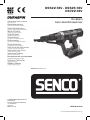
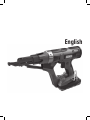
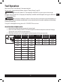
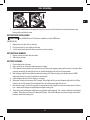
DURASPIN DS522-18V is a versatile auto-feed screwdriver designed for a broad range of applications in wood, metal, and plastic. It features an adjustable drive depth to precisely countersink screws and a powerful motor that delivers consistent performance. The tool also includes a belt hook for easy carrying and a trigger lock for added convenience.
DURASPIN DS522-18V is a versatile auto-feed screwdriver designed for a broad range of applications in wood, metal, and plastic. It features an adjustable drive depth to precisely countersink screws and a powerful motor that delivers consistent performance. The tool also includes a belt hook for easy carrying and a trigger lock for added convenience.


-
 1
1
-
 2
2
-
 3
3
-
 4
4
-
 5
5
-
 6
6
-
 7
7
-
 8
8
-
 9
9
-
 10
10
-
 11
11
-
 12
12
-
 13
13
-
 14
14
-
 15
15
-
 16
16
-
 17
17
-
 18
18
-
 19
19


DURASPIN DS522-18V is a versatile auto-feed screwdriver designed for a broad range of applications in wood, metal, and plastic. It features an adjustable drive depth to precisely countersink screws and a powerful motor that delivers consistent performance. The tool also includes a belt hook for easy carrying and a trigger lock for added convenience.
Ask a question and I''ll find the answer in the document
Finding information in a document is now easier with AI