
http://www.supermicro.com MNL-2568-QRG
SuperServer 741P-TR(T) Quick Reference Guide
CPU/Heatsink Installation
Caution
SAFETY INFORMATION
IMPORTANT: See installation instructions and safety warning
before connecting system to power supply.
http://www.supermicro.com/about/policies/safety_information.cfm
WARNING
To reduce risk of electric shock/damage to equipment,
disconnect power from server by disconnecting all power
cords from electrical outlets.
If any CPU socket empty, install protective plastic CPU cap
CAUTION
Always be sure all power supplies for this system have
the same power output. If mixed power supplies are
installed, the system will not operate.
For more information go to : http://www.supermicro.com/support
!
!
!
Rev. 1.0
12
3
Note: 1DPC applies to 1 SPC (Sockets Per Channel) or 2 SPC implementation.
SP XCC and SP MCC Carrier View
Heatsink SNK-P0088P
(for CPU1 and CPU2)
Note:
Thermal grease is pre-applied on new heatsinks. No additional thermal grease is needed.
CPU carrier is optional, Please select CPU carrier by CPU model. (E1A for XCC, E1B for MC)
DDR5 Memory Support for the 4th Generation Intel Xeon Scalable Processors
Type
Ranks Per DIMM
& Data Width
(Stack)
DIMM Capacity (GB)
Speed (MT/s); Voltage (V);
DIMM Per Channel (DPC)
1DPC (Note) 2DPC
16GB 1.1V
RDIMM
SRx8 (RC D) 16GB
4800 4400
SRx4 (RC C) 32GB
SRx4 (RC F) 9x4 32GB
DRx8 (RC E) 32GB
DRx4 (RC A) 64GB
DRx4 (RC B) 9x4 64GB
RDIMM 3DS (4R/8R) x4 (RC A) 2H-128GB
4H-256GB
LRDIMM/LRDIMM-3DS N/A N/A Not Supported Not Supported
Parameters Possible Values
Number of Channels per Socket 1, 2, 4, 6, 8
Number of DIMMs per Channel 1DPC (1 DIMM Per Channel) or 2DPC (2 DIMMs Per Channel)
DIMM Type RDIMM and 3DS RDIMM
DIMM Construction non-3DS RDIMM Raw Cards: A (2Rx4), C (1Rx4), D (1Rx8), E (2Rx8)
3DS RDIMM Raw Cards: A (4Rx4, 8Rx4)
9x4 RDIMM Raw Cards: B (2Rx4), F (1Rx4)
Compatible and Incompatible Type in a Channel and a System
DIMM Type RDIMM RDIMM 3DS 9x4 RDIMM
RDIMM Compatible Incompatible Incompatible
RDIMM 3DS Incompatible Compatible Incompatible
9x4 RDIMM Incompatible Incompatible Compatible
Key Parameters for DIMM Configurations
DIMM Population Guidelines for Optimal Performance
4TB memory capacity with 16 DIMMs of 256GB 3DS RDIMM/RDIMM DDR5 ECC memory.
For optimal memory performance, follow the instructions listed in the tables below when populating memory
modules.
Note: Memory speed and capacity support depends on the processors used in the system.
DDR5 Memory Population Table for X13 DP Motherboards (with 16 DIMMs installed)
1 CPU Memory Population Sequence
1 CPU & 1 DIMM P1-DIMMA1 or P1-DIMME1 or P1-DIMMB1 or P1-DIMMF1
1 CPU & 2 DIMMs P1-DIMMA1 / P1-DIMMG1 or P1-DIMMC1 / P1-DIMME1
1 CPU & 4 DIMMs P1-DIMMA1 / P1-DIMMC1 / P1-DIMME1 / P1-DIMMG1
1 CPU & 6 DIMM
P1-DIMMA1 / P1-DIMMC1 / P1-DIMMD1 / P1-DIMME1 / P1-DIMMF1 / P1-DIMMG1
or P1-DIMMA1 / P1-DIMMB1 / P1-DIMMC1 / P1-DIMME1 / P1-DIMMG1 / P1-DIMMH1
or P1-DIMMB1 / P1-DIMMC1 / P1-DIMMD1 / P1-DIMME1 / P1-DIMMF1 / P1-DIMMH1
or P1-DIMMA1 / P1-DIMMB1 / P1-DIMMD1 / P1-DIMMF1 / P1-DIMMG1 / P1-DIMMH1
1 CPU & 8 DIMMs P1-DIMMA1 / P1-DIMMB1 / P1-DIMMC1 / P1-DIMMD1 / P1-DIMME1 / P1-DIMMF1 / P1-DIMMG1 / P1-DIMMH1
2 CPUs (Recommended) Memory Population Sequence
2 CPUs & 2 DIMMs
2 CPUs & 4 DIMMs
CPU1: P1-DIMMA1, CPU2: P2-DIMMA1
or CPU1: P1-DIMME1, CPU2: P2-DIMME1
or CPU1: P1-DIMMB1, CPU2: P2-DIMMB1
or CPU1: P1-DIMMF1, CPU2: P2-DIMMF1
2 CPUs & 8 DIMMs
CPU1: P1-DIMMA1 / P1-DIMMG1, CPU2: P2-DIMMA1 / P2-DIMMG1
or CPU1: P1-DIMMC1 / P1-DIMME1, CPU2: P2-DIMMC1 / P2-DIMME1
CPU1: P1-DIMMA1 / P1-DIMMC1 / P1-DIMME1 / P1-DIMMG1
CPU2: P2-DIMMA1 / P2-DIMMC1 / P2-DIMME1 / P2-DIMMG1
2 CPUs & 12 DIMMs
2 CPUs & 16 DIMMs
CPU1: P1-DIMMA1/P1-DIMMC1/P1-DIMMD1/P1-DIMME1/P1-DIMMF1/P1-DIMMG1
CPU2: P2-DIMMA1/P2-DIMMC1/P2-DIMMD1/P2-DIMME1/P2-DIMMF1/P2-DIMMG1
CPU1: P1-DIMMA1/P1-DIMMB1/P1-DIMMC1/P1-DIMME1/P1-DIMMG1/P1-DIMMH1
CPU2: P2-DIMMA1/P2-DIMMB1/P2-DIMMC1/P2-DIMME1/P2-DIMMG1/P2-DIMMH1
CPU1: P1-DIMMB1/P1-DIMMC1/P1-DIMMD1/P1-DIMME1/P1-DIMMF1/P1-DIMMH1
CPU2: P2-DIMMB1/P2-DIMMC1/P2-DIMMD1/P2-DIMME1/P2-DIMMF1/P2-DIMMH1
CPU1: P1-DIMMA1/P1-DIMMB1/P1-DIMMD1/P1-DIMMF1/P1-DIMMG1/P1-DIMMH1
CPU2: P2-DIMMA1/P2-DIMMB1/P2-DIMMD1/P2-DIMMF1/P2-DIMMG1/P2-DIMMH1
CPU1: P1-DIMMA1/P1-DIMMB1/P1-DIMMC1/P1-DIMMD1/P1-DIMME1/P1-DIMMF1/P1-DIMMG1/P1-DIMMH1
CPU2: P2-DIMMA1/P2-DIMMB1/P2-DIMMC1/P2-DIMMD1/P2-DIMME1/P2-DIMMF1/P2-DIMMG1/P2-DIMMH1
Note: This memory configuration is recommended by Supermicro for optimal memory performance.
Please use this configuration to maximize your memory performance.
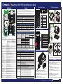
Jumper
Quick Reference Table
JBT1
JPL1
Default Setting
Open (Normal)
Pins 1-2 (Enabled)
Connector Description
BT1 Onboard CMOS Battery
BMC_LAN Dedicated BMC LAN Port
COM1 Rear I/O COM Port
FAN1 - FAN6, FANA, FANB
I-SATA0, I-SATA1
JBP_I2C1
Intel PCH Powered I-SATA 3.0 Ports with support of SuperDOM
devices *DOM: Disk on Module
JCOM2
JF1
JFP2
JIPMB1
4-pin BMC External I²C Header
Front Accessible COM Port Header
Front Control Panel Header
Front Accessible VGA Connection Header
JL1
JNCSI1
JNVI2C1
JPCIE1 (SLOT1),
JPCIE6 (SLOT6) PCIe 5.0 x8 Slots (SLOT1: supported by CPU1, SLOT6: supported
by CPU2)
4-pin BMC External I²C Header (for Inlet Temperature Sensor)
Chassis Intrusion Header
NC-SI (Network Controller Sideband Interface) Connector
NVMe SMBus I²C Header with hot-plug support
JPCIE2/3 (SLOT2/3),
JPCIE4/5 (SLOT4/5)
JPI2C1
JPWR1, JPWR2, JPWR4
PCIe 5.0 x16 Slots (SLOT2/3: supported by CPU1, SLOT4/5:
supported by CPU2)
Power System Management Bus (SMBus) I²C Header
8-pin Power Connectors
JPWR3 24-pin ATX Power Connector
JS1 (SATA 0 - SATA7)
JSD1, JSD2
SlimSAS x8 Connector with support of eight Intel PCH SATA 3.0
connections (RAID 0, 1, 5, and 10 supported)
JSTBY1
SATA DOM Power Connectors
5V Standby Power Header
Description
CMOS Clear
LAN1, LAN2
Enable/Disable
LED
LED4, LED7
LED6
LEDBMC
LEDPWR
StatusDescription
BMC Heartbeat LED
Power LED
Unit Identifier (UID) LED
M.2 LEDs (for M.2-C1, M.2-C2)
Blinking Green: BMC Normal (Active),
Solid Green: (During BMC Reset or
during a Cold Reboot)
LED On: Onboard Power On
Solid Blue: Unit Identified
Blinking Green: Device Working
CPU/System Fan Headers
Ethernet LAN (RJ45) Port 1 and Port 2 (1G LAN support on
X13DEI and 10G LAN support on X13DEI-T)
SATA DOM Power Connectors
5V Standby Power Header
Trusted Platform Module/Port 80 Header
PCIe 4.0 x2 NVMe M.2 Slots supported by CPU1 (with
support of M-Key 2280 and 22110)
MCIO x8 Connectors supported by CPU1 with four PCIe 5.0
x4 NVMe connections
MCIO x8 Connector supported by CPU2 with two PCIe 5.0 x4
NVMe connections
Serial General Purpose I/O Header (for I-SATA0/1 SuperDOM
support)
USB 2.0 Header with support of two USB connections
JSD1, JSD2
JSTBY1
JTPM1
JUIDB1
LAN1, LAN2
M.2-C1, M.2-C2
P1_NVME0/1 (JNVME1)
P1_NVME2/3 (JNVME2)
P2_NVME4/5 (JNVME3)
S-SGPIO1
USB0/1
USB2
USB3/4 (3.0)
USB5/6 (3.0)
USB7/8 (3.0)
VGA
Internal USB 2.0 Vertical Type-A Connector
Back Panel USB 3.0 Ports (5Gbps, Type-A)
Back Panel USB 3.0 Ports (5Gbps, Type-A)
USB 3.0 Header with support of two USB connections
Rear I/O VGA Port
Unit Identifier (UID) Switch / BMC Reset Button
Pin 1
SP MCC
Carrier E1B
Pin 1
Pin 1
Pin 1
SP XCC
Carrier E1A
Front View & Interface
Rear View
Storage Module
Rotating the Optional Storage Module
Rotating the Storage Module for Rack Mounting
1. Open the chassis cover.
2. Locate the storage module and disconnect any cables from the storage module
to any component in the chassis.
3. Push the storage module release lever. This lever unlocks the storage module.
4. Grasp the external edges of the storage module and pull the unite from the
chassis.
5. Turn the storage module 90 degrees.
6.
Reinsert the module into the chassis and reconnect the cords.
USB Ports
Power Failure LED
Information LED
LAN1 LED & LAN2 LED
Device Activity LED
Power LED
Reset Button
Power Button
1
2
3
4
5
6
7
8
Description
No.
Description
No.
1
2
3
4
5
6
7
8
9
10
11
12
13
Redundant 1200W Power Supply
2x Rear Fans
Serial Port
Dedicated IPMI LAN Port
4 USB 3.0 Ports
2x LAN Ports
VGA Port
PCI-E 5.0 x8 Slot, Full Height
PCI-E 5.0 x16 Slot, Full Height
PCI-E 5.0 x16 Slot, Full Height
PCI-E 5.0 x16 Slot, Full Height
PCI-E 5.0 x16 Slot, Full Height
PCI-E 5.0 x8 Slot, Full Height
2
735
816 4
3
7
4
5
6
1
2
9
8
10
12
11
13
Release Lever
Latch
Latch
Processor (Reverse Side Up)
CPU Key
Carrier (Top Side Up)
CPU Key
Latch
Latch
Processor Carrier Assembly
Pin1
A
B
C
D
a
b
c
d
A, B, C, D: Peek Nut
1, 2, 3, 4: Rotating Wire
a, b, c, d: Threaded Fastener
Peek Nut
(Unlatched) (latched)
Rotating Wire
3
1
d
a
b
c
Rotating Wire
B
C
D
Rotating Wire
APeek Nut
2
Rotating Wire 4
Threaded Fastener
Heatsink
CPU Socket
T30 Torx Driver
Use a torque
of 12 lbf
SAN MAC
IPMI CODE BAR CODE
MAC CODE
BIOS LICENSE
LAN
CTRL
BMC
JSTBY1
JUIDB1
S-SGPIO1
JFP2
BT1 JPI2C1
JNCSI1
JSD1
JSD2
JBT1
LEDBMC
LED4
JF1
JPWR3JPWR1JPWR2 JPWR4
JNVI2C1 JIPMB1 JPL1
JL1
JTPM1
FAN6
FAN5
FANB
FANA
FAN1
FAN2
FAN4 FAN3
USB2
LED7
M.2-C2
(NVME ONLY)
JCOM2
USB5/6 (3.0)
M.2-C1 (NVME ONLY)
USB0/1
USB7/8 (3.0)
USB3/4 (3.0)
BMC_LAN
LAN2
P2_NVME4/5
P1_NVME2/3
JNVME1
P1_NVME0/1 JBP_I2C1
JNVME2
JNVME3
COM1
LAN1
JS1(SATA0~7 )
I-SATA1
I-SATA0
CPU1
SLOT1
PCIe
5.0
X8
CPU1
SLOT2
PCIe
5.0
X16
CPU1
SLOT3
PCIe
5.0
X16
CPU2
SLOT4
PCIe
5.0
X16
CPU2
SLOT5
PCIe
5.0
X16
P1-DIMMH1
P1-DIMMG1
P1-DIMMF1
P1-DIMME1
P1-DIMMA1
P1-DIMMB1
P1-DIMMC1
CPU2
SLOT6
PCIe
5.0
X8
P1-DIMMD1
P2-DIMMB1
P2-DIMMD1
P2-DIMMC1
P2-DIMMA1
PWR
LED
VGA
LED6
(UID-LED)
X13DEI(-T)
DESIGNED IN USA
PCH
REV:1.01
CPU2
CPU1
P2-DIMMG1
P2-DIMME1
P2-DIMMF1
P2-DIMMH1
JPCIE1 JPCIE6
JPCIE2 JPCIE3 JPCIE4 JPCIE5
JIPMB1
COM1
LED6
FAN6
USB3/4(3.0)
BMC_LAN
LAN2
LAN1
VGA
FAN5
JUIDB1
LEDBMC
JPCIE1
JPCIE2
JPCIE4
JPCIE5
JPCIE3JPCIE6
USB7/8(3.0)
USB2
I-SATA1
I-SATA0
JSD1
JSD2
USB0/1
SATA0-7
S-SGPIO1
JL1
JTPM1
P2_NVME4/5
JPWR2
JPWR1
JPWR3
JPI2C1
JF1
LEDPWR
JPWR4
JPL1
JBT1
JRK1
M.2-C1
LED4
JNVI2C1
JNCSI1
JFP2
JCOM2
FANB
FAN4
FANA
JBP_I2C1
FAN3
FAN2
FAN1
P1_NVME2/3
P1_NVME0/1
M.2-C2
BT1
JSTBY1
LED7
USB5/6(3.0)

 1
1

Supermicro X11DPU-XLL User manual
Supermicro X10DRX User manual
Supermicro H11DSi User manual
Supermicro X10DRL-CT User manual