JBL AEC65 User manual

Category
Loudspeakers
Type
User manual

This manual is also suitable for

Indoor Speakers
Cat. Nos.
AEC65
AEC80
AEI65
AEI80
AEM65
USER GUIDE
AEC65
AEC80
Ceiling Speaker
AEM65
Dual Tweeter
Stereo Ceiling
Speaker
AEI65
AEI80
In-Wall Speaker
PK-93410-10-00-2A
OVERVIEW
Thank you for choosing Leviton Architectural Edition™
powered by
JBL.
Please take a moment to register your product on our Web site at
www.leviton.com. It enables us to keep you posted on our latest
advancements, and helps us to better understand our customers and
build products that meet their needs and expectations.
PARTS INCLUDED
Cat. Nos. AEI65 and AEI80
One pair of speakers with grilles.
Cat. Nos. AEC65 and
AEC80
One pair of speakers with grilles.
Template/Paint
Shield.
Remove paint
shield (inner
rectangle) at
perforation.
Template/Paint
Shield.
Remove paint
shield (inner
rectangle) at
perforation.
Cat. Nos. AEM65
One speaker with grille.
Template/Paint
Shield.
Remove paint
shield (inner
rectangle) at
perforation.
2
SPEAKER PLACEMENT
WALL
40
0
–60
0
WALL
WA
LL
WALL
WA
LL
5-6 ft.
Front Speaker Mounting
Rear Speaker Mounting
Ceiling Speaker Mounting
Proper placement of the speakers is an important step in obtaining
the most realistic soundstage possible. These recommendations are
for the optimum placement of the loudspeakers. Use these placement
recommendations as a guide. Slight variations will not diminish your
listening pleasure.
The front speakers should be placed the same distance from each
other as they are from the listening position. They should be placed at
about the same height from the floor as the listenerʼs ears will be, with
the tweeters aimed toward the listener at ear-level height.
In a home theater configuration, the two surround speakers should
be placed slightly behind the listening position and ideally should face
each other and be at a level higher than the listenerʼs ears. If that is
not possible, they may be placed in a wall (or in the ceiling) behind the
listening position, facing forward.
3
SPEAKER CONNECTIONS
The surround speakers should not call attention to themselves. They
should provide a diffuse, ambient sound accompanying the main
program material heard in the front speakers. In Dolby* Digital and DTS®
systems, aim the tweeters toward the listening position at ear-level height.
Dual Tweeter Stereo Speaker, Cat. No. AEM65:
Model AEM65 has the capability of playing two channels through one
loudspeaker, thanks to its dual-tweeter/dualvoice-coil construction. Since
the tweeters are close together, in general they should be aimed away
from each other for best coverage.
For two-channel (stereo) applications, e.g., as a single speaker in a
remote room of a distributed audio system, install the AEM65 stereo
speaker centrally in the ceiling for best stereo imaging, swiveling the
tweeters so that one points toward the left and the other toward the right
of the listening position, aimed at ear level height.
The AEM65
stereo speaker may also be used to play the left and right
surround channels in a 5.1-channel home theater system, in which case
it should be mounted in the ceiling slightly behind the listening position,
centered from left to right and with the tweeters pointing toward the left
and right of the listening position, aimed at ear-level height. For
7.1-channel systems where it is desired to use two AEM65 stereo
speakers, one to play both the left surround and surround back channels
and the other to play both the right surround and surround back
channels, mount each AEM65 stereo speaker in the ceiling, slightly
behind the listening position, one closer to the left side of the room and
the other closer to the right side. Aim the tweeters away from each other,
toward the front and rear of the room.
LEFT
LEFT
RIGHT
RIGHT
The wires for both speakers should be
the same length. If one speaker is placed
closer to the amplifier than the other,
Hide the excess wire behind the wall.
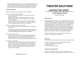
Speakers and electronics terminals have
corresponding (+) and (–) terminals.
Most manufacturers of speakers and
electronics, including Leviton Architectural
Edition powered by JBL, use Red to
denote the (+) terminal and Black for the
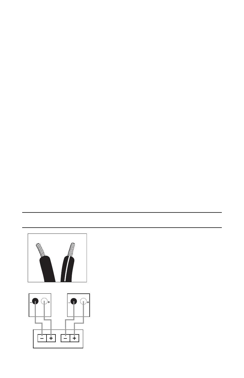
(–) terminal. It is important to connect both
speakers identically: (+) on the speaker
to (+) on the amplifier and (–) on the
speaker to (–) on the amplifier. Wiring “out
of phase” results in thin sound, weak bass
and a poor stereo image. With the advent
Front and Rear Speaker Output
4
of multichannel surround sound systems, connecting all of the speakers
in your system with the correct polarity remains equally important in
order to preserve the proper ambience and directionality of the program
material. To use the push-type speaker terminals, press the red (+) or
black (–) cap for the desired terminal, insert the bare end of the speaker
wire into the hole below the cap and release the cap. Gently tug on the
wire to make sure that it is fully inserted.
The side of the wire that is Red, with a ridge, or other coding is usually
considered positive polarity (i.e., +). For wire runs inside the wall, be
sure to use a CL2/3 fire rated cable (refer to local codes). Also, consult
the ownerʼs manuals that were included with your amplifier or receiver to
confirm connection procedures.
WIRE LENGTH RECOMMENDED SIZE
Up to 20 ft. 16 gauge
Up to 30 ft. 14 gauge
Greater than 30 ft. 12 gauge
INSTALLATION
WARNING: TO BE INSTALLED AND/OR USED IN ACCORDANCE
WITH APPROPRIATE ELECTRICAL CODES AND REGULATIONS.
NOTE: LEVITON/JBL IN-WALL AND CEILING SPEAKERS WERE
DESIGNED TO BE EASILY INSTALLED. HOWEVER, IF YOU ARE
UNSURE OF YOUR ABILITY TO PROPERLY INSTALL THESE
LOUDSPEAKERS, PLEASE CONTACT YOUR DEALER OR A
QUALIFIED INSTALLER.
NOTE: SPEAKER WIRE RUNS SITUATED INSIDE A WALL NEED
TO BE FIRE-RATED. WHEN IN DOUBT, CONSULT YOUR LOCAL
ELECTRICAL INSPECTOR FOR CORRECT WIRE RATINGS.
Tools Required:
Pencil
Measuring Tape
Carpenterʼs Level
Phillips #2 Screwdriver
Utility Knife
Awl
5
IN-WALL SPEAKER INSTALLATION – EXISTING
CONSTRUCTION:
1/2"
1/2"
1/2"
Level
Te
mplate
Step 1:
Remove the grille from the
speaker frame by pulling on
the paper tab. If the tab is
missing, to avoid scratching
the grille or baffle you may
unfold a paper clip, insert the
straight end through one of
the holes in the grille, and
gently pull up.
Step 2:
Determine the correct
speaker location.
NOTE: Remove the inner
template, which is the paint
shield, at the perforation.
Use the outer template when
cutting the drywall.
Step 3:
Always allow at least one-
half inch between a wall stud
and the speaker cutout or
the locking tabs will not be
able to swivel into place.
Step 4:
Cut the drywall.
Step 5:
Connect the speaker wires
to the speaker.
Step 6:
Place the frame assembly in
the wall.
Step 7:
Screw down each of the four
Phillips head screws. The
locking tabs will swivel into
place and secure the unit
to the rear surface of the
drywall.
Step 8:
Replace the metal grille.
The speakers feature unique swivel mounts for the tweeters that enable you to aim the very
directional high frequencies toward the listening position, at ear-level height. Before installing
the speaker grille, gently press on the outer edge of the tweeter mount to adjust the position of
the tweeter. The tweeter will not swivel more than 15 degrees in any direction; do not attempt to
force it to move further. You may also rotate the tweeter to orient the JBL logo as desired.
6
CEILING SPEAKER INSTALLATION – EXISTING
CONSTRUCTION:
1/2"
1/2"
1/2"
Level
Te
mplate
Step 1:
Remove the grille from the
speaker frame by pulling on
the paper tab. If he tab is
missing, to avoid scratching
the grille or baffle you may
unfold a paper clip, insert the
straight end through one of
the holes in the grille, and
gently pull up.
Step 2:
Determine the correct
speaker location.
NOTE: Remove the inner
template, which is the paint
shield, at the perforation.
Use the outer template when
cutting the drywall.
Step 3:
Always allow at least one-
half inch between a wall stud
and the speaker cutout or
the locking tabs will not be
able to swivel into place.
Step 4:
Cut the drywall.
Step 6:
Place the frame assembly in
the wall.
Step 5:
Connect the speaker wires
to the speaker. NOTE: Cat.
No. AEM65 requires two
sets of speaker wires, one
for each channel.
Step 7:
Screw down each of the four
Phillips head screws. The
locking tabs will swivel into
place and secure the unit
to the rear surface of the
drywall.
Step 8:
Replace the metal grille.
7
The speakers feature unique swivel mounts for the tweeters that enable you to aim the
very directional high frequencies toward the listening position, at ear-level height. Before
installing the speaker grille, gently press on the outer edge of the tweeter mount to adjust
the position of the tweeter. The tweeter will not swivel more than 15 degrees in any
direction; do not attempt to force it to move further. You may also rotate the tweeter to
orient the JBL logo as desired.
The dual tweeters of speaker, Cat. No. AEM65, may be swiveled independently.
Optimum imaging will be obtained by aiming the tweeters to the left and right of the
listening position, at ear-level height, if your application permits.
Leviton Architectural Edition powered by JBL loudspeakers can be
painted to match any decor. If you wish to change their color, the satin
finish on the grille and frame will function as a primer coat. Before
painting, install the paint shield (inner section of template in the assembly
kit) securely into the recess in the baffle. This will protect the speaker
components and baffle from paint residue. Use a high-quality spray paint,
and apply a thin coat of color.
Be certain the grille perforations remain free of paint. Filling them with
paint will diminish the sound quality.
NOTE: Gently remove the acoustical foam blanket from the grille before
painting. Reattach the blanket after the paint has dried.
PAINTING THE SPEAKER
FRAME AND GRILLE
8
TROUBLESHOOTING
IF THERE IS NO SOUND FROM ANY OF THE SPEAKERS:
• Check that receiver/amplifier is on and a source is playing.
• Check all wires and connections between receiver/amplifier and
speakers. Make sure all wires are connected. Make sure none of the
speaker wires are frayed, cut, punctured or touching each other.
• Review proper operation of your receiver/amplifier.
IF THERE IS NO SOUND COMING FROM ONE SPEAKER:
• Check the “Balance” control on your receiver/amplifier.
• Check all wires and connections between receiver/amplifier and
speakers. Make sure all wires are connected. Make sure none of the
speaker wires are frayed, cut, punctured or touching each other.
IF THERE IS LOW (OR NO) BASS OUTPUT:
• Make sure the connections to the left and right “Speaker Inputs” have
the correct polarity (+ and –).
• Consider adding a powered subwoofer to your system.
• In Dolby Digital or DTS modes, make sure your receiver/processor
is correctly configured. When using a subwoofer, make sure the
subwoofer output of the receiver/ processor has been enabled. If
no subwoofer is being used, make sure the left and right front and
rear speakers have been configured as “LARGE.” See your receiver/
processorʼs ownerʼs manual for further information on correct speaker
configuration in Dolby Digital, DTS and other surround sound modes.
IF THE SYSTEM PLAYS AT LOW VOLUMES BUT SHUTS OFF AS
VOLUME IS INCREASED:
• Check all wires and connections between receiver/amplifier and
speakers. Make sure all wires are connected. Make sure none of the
speaker wires are frayed, cut , punctured or touching each other.
• If more than one pair of main speakers is being used, check the
minimum-impedance requirements of your receiver/amplifier.
9
SPECIFICATIONS
AEM65
Frequency
Response
40Hz–20kHz (+10dB)
Recommended Maximum
Amplifier Power †
100 watts
Impedance
8 ohms nominal
Sensitivity
88dB (2.83V/1m)
Crossover Frequency
3,000Hz
Woofer
6-1/2" Titanium-laminate
cone w/rubber surround
Tweeter
Dual 3/4" (19mm) Titanium-laminate
dome, w/Elliptical Oblate
Spheroidal
TM
waveguide
and swivel mounts
Plate Size (Dia.)
9-3/16" (233mm)
Mounting Cutout Size (Dia.)
7-7/8" (200mm)
Mounting Depth
4-1/4" (108mm)
Weight per Speaker
4 lb (1.8kg)
AEC65
Frequency
Response
40Hz–20kHz (+10dB)
Recommended Maximum
Amplifier Power †
80 watts
Impedance
8 ohms nominal
Sensitivity
88dB (2.83V/1m)
Crossover Frequency
3,000Hz
Woofer
6-1/2" Titanium-laminate
cone w/rubber surround
Tweeter
1" Titanium-laminate
dome, w/Elliptical Oblate
Spheroidal
TM
waveguide
and swivel mount
Plate Size (Dia.)
9-3/16" (233mm)
Mounting Cutout Size (Dia.)
7-7/8" (200mm)
Mounting Depth
4-1/4" (108mm)
Weight per Speaker
3.85 lb (1.7kg)
NOTES:
• All features and specifications are subject to change without notice.
• † The maximum recommended amplifier power rating will ensure
proper system headroom to allow for occasional peaks. We do not
recommend sustained operation at these maximum power levels.
• * Trademark of Dolby Laboratories.
DTS is a registered trademark of Digital Theater Systems, Inc.
10
AEC80
Frequency
Response
32Hz–20kHz (+10dB)
Recommended Maximum
Amplifier Power †
100 watts
Impedance
8 ohms nominal
Sensitivity
89dB (2.83V/1m)
Crossover Frequency
3,000Hz
Woofer
8.0” Titanium-laminate
cone w/rubber surround
Tweeter
1" Titanium-laminate
dome, w/Elliptical Oblate
Spheroidal
TM
waveguide
and swivel mount
Plate Size (Dia.)
10-7/8" (275mm)
Mounting Cutout Size (Dia.)
9-1/2" (240mm)
Mounting Depth
4-1/4" (108mm)
Weight per Speaker
4.5 lb (2.0kg)
AEI65
Frequency
Response
38Hz–20kHz (+10dB)
Recommended Maximum
Amplifier Power †
80 watts
Impedance
8 ohms nominal
Sensitivity
88dB (2.83V/1m)
Crossover Frequency
3,000Hz
Woofer
6-1/2" Titanium-laminate
cone w/rubber surround
Tweeter
1" Titanium-laminate
dome, w/Elliptical Oblate
Spheroidal
TM
waveguide
and swivel mount
Plate Size (W x H)
8-1/2" x 11" (216mm x 279mm)
Mounting Cutout Size (W x H)
7-1/8" x 9-11/16" (181mm x 246mm)
Mounting Depth
3-7/8" (98mm)
Weight per Speaker
4.3 lb (2.0kg)
SPECIFICATIONS
11
AEI80
Frequency
Response
30Hz–20kHz (+10dB)
Recommended Maximum
Amplifier Power †
100 watts
Impedance
8 ohms nominal
Sensitivity
89dB (2.83V/1m)
Crossover Frequency
3,000Hz
Woofer
8.0" Titanium-laminate
cone w/rubber surround
SPECIFICATIONS
For additional information, contact Levitonʼs Techline at
1-800-824-3005 or visit Levitonʼs website at www.leviton.com
Tweeter
1" Titanium-laminate
dome, w/Elliptical Oblate
Spheroidal
TM
waveguide
and swivel mount
Plate Size (W x H)
10-1/8" x 13-1/8" (257mm x 333mm)
Mounting Cutout Size (W x H)
8-7/8" x 11-13/16" (225mm x 300mm)
Mounting Depth
4" (102mm)
Weight per Speaker
5.5 lb (2.5kg)
LIMITED 5 YEAR WARRANTY AND EXCLUSIONS
Leviton warrants to the original consumer purchaser and not for the benefit of anyone else that this product at the time of
its sale by Leviton is free of defects in materials and workmanship under normal and proper use for five years from the
purchase date. Levitonʼs only obligation is to correct such defects by repair or replacement, at its option, if within such
five year period the product is returned prepaid, with proof of purchase date, and a description of the problem to
Leviton
Manufacturing Co., Inc., Att: Quality Assurance Department, 59-25 Little Neck Parkway, Little Neck, New York
11362-2591. This warranty excludes and there is disclaimed liability for labor for removal of this product or reinstallation.
This warranty is void if this product is installed improperly or in an improper environment, overloaded, misused, opened,
abused, or altered in any manner, or is not used under normal operating conditions or not in accordance with any labels
or instructions. There are no other or implied warranties of any kind, including merchantability and fitness for a
particular purpose, but if any implied warranty is required by the applicable jurisdiction, the duration of any such implied
warranty, including merchantability and fitness for a particular purpose, is limited to five years. Leviton is not liable
for incidental, indirect, special, or consequential damages, including without limitation, damage to, or loss of
use of, any equipment, lost sales or profits or delay or failure to perform this warranty obligation. The remedies
provided herein are the exclusive remedies under this warranty, whether based on contract, tort or otherwise.
170-0083
PK-93410-10-00-2A
06-000-05428-E
  • Page 1 1
  • Page 2 2
  • Page 3 3
  • Page 4 4
  • Page 5 5
  • Page 6 6
  • Page 7 7
  • Page 8 8
  • Page 9 9
  • Page 10 10
  • Page 11 11
  • Page 12 12

JBL AEC65 User manual

Category
Loudspeakers
Type
User manual
This manual is also suitable for

Ask a question and I''ll find the answer in the document

Finding information in a document is now easier with AI