Page is loading ...

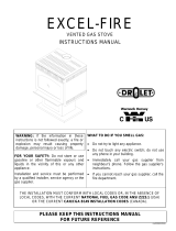
EXEL-FIRE
GAS STOVE
INSTALLATION AND OPERATING INSTRUCTIONS
WARNING: FAILURE TO CAREFULLY FOLLOW INSTRUCTIONS IN THIS
MANUAL MAY RESULT IN FIRE OR EXPLOSION CAUSING PROPERTY
DAMAGE, PERSONAL INJURY OR LOSS OF LIFE.
FOR YOUR SAFETY
DO NOT STORE OR USE GASOLINE OR OTHER FLAMMABLE VAPORS AND
LIQUIDS IN THE VICINITY OF THIS OR ANY OTHER APPLIANCE.
FOR YOUR SAFETY
IF YOU SMELL GAS :
1. DO NOT TRY TO LIGHT ANY APPLIANCE
2. OPEN WINDOWS
3. TURN OFF MAIN GAS SUPPLY
4. DO NOT TOUCH ELECTRICAL SWITCHES
5. EXTINGUISH ANY OPEN FLAME
6. CALL YOUR GAS SUPPLIER IMMEDIATELY
INSTALLATION AND SERVICE MUST BE PERFORMED BY A QUALIFIED
TECHNICIAN, SERVICE AGENCY OR GAS SUPPLIER
Manufactured by :
DROLET STOVES AND FIREPLACES INC.
1700, Leon-Harmel
Quebec, Qc (Canada)
G1N 4R9
Tested by :
WARNOCK HERSEY
REV. 7/96 45052A

1
TABLE OF CONTENTS
GENERAL INFORMATION :............................................................................. 2
WARNING :........................................................................................................ 3
SPECIFICATIONS :............................................................................................ 4
TOP, SIDE AND FRONT VIEWS :......................................................... 5 - 6
OPTIONAL BLOWER INSTALLATION............................................................ 7
CLEARANCE DISTANCES AWAY FROM FLAMMABLE MATERIALS....... 7
INSTALLATION :............................................................................................... 8 to 13
INSTALLATION OF THE UNIT............................................................. 8
PEDESTAL SELF-ADHESIVE GOLD STRIP INSTALLATION............ 8
GLASS FRONT REMOVAL CLEANING AND INSTALLATION :........ 9
BURNER REMOVAL AND INSTALLATION :...................................... 10
VENTURI TUBE ADJUSTMENT............................................................ 11
LOG INSTALLATION :........................................................................... 12
EMBERS KIT INSTALLATION :............................................................ 13
OPERATING INSTRUCTIONS :......................................................................... 14
LIGHTING INSTRUCTIONS :................................................................. 15
SHUTOFF INSTRUCTIONS :................................................................... 15
MAINTENANCE INSTRUCTIONS :................................................................... 16
PILOT ADJUSTMENT ........................................................................................ 17
PRESSURE READING AND ADJUSTMENT...................................................... 17
TEMPERATURE SENSING BULB ADJUSTMENT............................................ 18
HIGH ALTITUDE ADJUSTMENTS.................................................................... 18
OPTIONAL 6-INCH PIPE INSTALLATION........................................................ 18
OPTIONAL PARTS ............................................................................................. 19
REPLACEMENT PARTS..................................................................................... 19
LIMITED 5-YEAR WARRANTY :....................................................................... 20

2
GENERAL INFORMATION
The EXEL-FIRE gas stove is a high-efficiency free-standing gas appliance with a
maximum input rating of 28,000 Btu/h with natural gas or 28,000 Btu/h with propane. It
features a thermostatic modulating valve and a constant pilot. This means flame height
will vary according to room temperature. The cooler the ambient temperature, the larger
the flame. The valve is also independent of any outside electrical supply. The appliance
will therefore continue to heat your home in the event of a power failure.
To improve efficiency, a 130 CFM blower with speed control and thermo-switch is
available for optional automatic on/off control.
Read these instructions and consult local building authorities before installing this
appliance. Install the unit and its venting system only as directed in these instructions.
CONSERVE THESE INSTRUCTIONS FOR FUTURE REFERENCE
This gas stove has been tested by WARNOCK HERSEY in accordance with CAN1-2.1-
M86, ANSI Z21.11.1 1991 and Z21.11.1a 1993 standards.

3
WARNING
• THIS HEATER MUST BE PROPERLY CONNECTED TO A VENTING SYSTEM.
THIS HEATER IS EQUIPPED WITH A SHUTOFF SAFETY SYSTEM TO
PROTECT AGAINST IMPROPER VENTING OF COMBUSTION FUEL.
• THIS APPLIANCE MUST BE INSTALLED IN ACCORDANCE WITH LOCAL
BYLAWS WHERE APPLICABLE. WHERE NO BYLAWS EXIST,
INSTALLATION MUST BE MADE IN ACCORDANCE WITH THE CURRENT
CAN/CGA B-149 OR ANSI Z223-1 STANDARDS.
• ALWAYS ENSURE ADEQUATE AIR SUPPLY FOR PROPER BURNING. FOR
MORE INFORMATION, CONSULT THE CAN/CGA B-149 OR AINSI Z223-1
STANDARDS OR LOCAL BYLAWS.
• DO NOT BURN WOOD OR ANY OTHER MATERIAL IN THIS APPLIANCE.
• HOT WHEN IN OPERATION. KEEP CHILDREN, FURNITURE, CLOTHING AND
FLAMMABLE MATERIAL AWAY FROM THE APPLIANCE. INSTALL AWAY
FROM HEAVY TRAFFIC AREAS.
• ADVISE ADULTS AND CHILDREN OF THE HAZARD OF HIGH SURFACE
TEMPERATURES AND THAT CONTACT MAY RESULT IN BURNS OR IGNITE
CLOTHING.
• YOUNG CHILDREN MUST BE SUPERVISED WHEN IN THE SAME ROOM AS
THE APPLIANCE.
• THE APPLIANCE MUST BE INSPECTED BEFORE USE AND THEREAFTER,
ONCE A YEAR BY QUALIFIED SERVICE TECHNICIAN. MORE FREQUENT
CLEANING MAY BE REQUIRED DUE TO EXCESSIVE LINT FROM
CARPETING, BEDDING MATERIAL, ETC.
• CONTROL COMPARTMENTS, BURNERS AND CIRCULATING AIR
PASSAGEWAYS MUST BE KEPT CLEAN.
• DO NOT MODIFY THIS APPLIANCE.
• OPENINGS IN THE GAS STOVE PEDESTAL MUST NEVER BE OBSTRUCTED.
• PROVIDE ADEQUATE ACCESS FOR SERVICING AND PROPER OPERATION.
• THIS APPLIANCE MUST NOT BE CONNECTED TO A CHIMNEY FLUE
WHERE SOLID FUELS ARE CURRENTLY BURNED.

4
SPECIFICATIONS
Dimensions :
height : 29 1/2”
width : 24”
depth : 18”
Glass : 19.45" x 11.74" 1400° F clear ceramic
Fuel : Propane Gas Natural Gas
Maximum input rating : 28 000 (8206) 28 000 (8206) Btu/h (Watts)
Manifold pressure : 10 (2.5) 3.5 (0.9) w.c. (kPa)
Minimum input rating: 22 000 (6500) 20 000 (59000) Btu/h (Watts)
Minimum inlet pressure: 11 (2.7) 5 (1.7) po d’eau (kPa)
Maximum inlet pressure: 14 (3.5) 7 (1.8) po d’eau (kpa)
Output capacity (Fan off): 21 000 (6150) 21 000 (6150) Btu/h (Watts)
Output capacity (Fan on): 22 500 (6600) 22 500 (6600) Btu/h (Watts)
Efficiency (Fan off): 75% 75%
Efficiency (Fan on): 80% 80%
Vent pipe "B-vent" or "L-vent" certified 4” Diameter vent pipe
Valve: S.I.T., Eurosit 630 model
thermostatic modulating
Blower : 130 CFM, variable speed
Thermo-switch :110° F “ON”, 90° F “OFF”, bi-metal type.

5
TOP, FRONT AND SIDE VIEWS

6

7
OPTIONAL BLOWER INSTALLATION
See instruction sheet included with optional blower before proceeding with installation.
INSTALLATION
CLEARANCE DISTANCES AWAY FROM FLAMMABLE
MATERIALS
The stove location must respect clearance distances away from flammable materials.
• For clearance between pipe and flammable materials, follow vent pipe manufacturer’s
instructions.
• If the appliance is installed directly on carpeting or other flammable material other
than wood flooring, the appliance must be installed on a metal or wood panel
extending the full width and depth of the appliance pedestal (13" x 18").

8
INSTALLATION OF UNIT
•
Move the Exel-Fire to the desired position. Mark the location for the gas inlet pipe
and the location where the vent pipes will go through the wall. Remove the appliance.
•
Route a 3/8" minimum NPT iron pipe gas line to the desired location.
•
Install a shutoff valve on the gas line. Tighten securely using a pipe joint compound.
•
Install a 1/8" NPT plugged tapping for the test gauge connection immediately beside
the shutoff valve, between the shutoff valve and the appliance.
•
Move the Exel-Fire to the desired position and secure in place with four screws.
•
Connect the gas line to the steel connector supplied. Remove the burner (see page 10)
if the gas connection is not accessible.
FLEX CONNECTOR
SHUT OFF VALVE
PLUGGED TAPPING
STEEL GAS LINE
GAS VALVE
•
Check the gas line piping for leaks. Use a soap and water solution.
WARNING : DO NOT
USE AN OPEN FLAME TO CHECK FOR LEAKS.
PEDESTAL SELF-ADHESIVE GOLD STRIP INSTALLATION
• Slide the base around the pedestal as shown on drawing (page 9) of operating
instructions.
• Remove the red and green plastic bands from the gold strip.
• Start sticking the self-adhesive gold strip from the rear corner of pedestal and 1/16"
(1.5 mm) over the base. The strip covers only the sides and the front of the pedestal.

9
GLASS FRONT REMOVAL, CLEANING AND INSTALLATION
Removal :
- Allow the stove to cool for at least one hour.
- Remove the two (2) screws on the left and right, at the bottom of the glass
front assembly.
- Remove the glass front assembly
CAUTION : Do not operate your stove without a glass front or if the glass is
broken.
Cleaning :
- Clean glass only when cold.
- Clean with a liquid cleaner or soap and water; do not use abrasive cleaners,
which can scratch the glass.
Installation :
- Place the glass front assembly back in position. Align the holes for screws.
- Install the two (2) screws.

10
BURNER REMOVAL AND INSTALLATION
REMOVAL :
- Remove the glass front assembly as shown on page 9
- Remove the two (2) screws holding the burner.
- Slide the burner to the left and pull towards you.
INSTALLATION :
- Place the burner assembly back in the fire box and push to the right until it
touches the valve support.
- Ensure that the main orifice is inserted into the venturi tube by looking through
the square hole shown.
- Reinstall the two (2) screws to secure the burner.
WARNING: NEVER OPERATE THE GAS STOVE WITHOUT HAVING THE
ORIFICE PROPERLY INSERTED INTO THE VENTURI TUBE. FAILURE TO
DO SO MAY RESULT IN SERIOUS DAMAGE TO THE GAS INSERT AND
CAUSE A FIRE.

11
VENTURI TUBE ADJUSTMENT
• The venturi tube must be correctly adjusted to ensure efficient burning. If the flame is
blue and small, close the venturi tube. If the flame is yellow and long (possible carbon
deposit), open the venturi tube.
• The venturi tube is normally adjusted at the factory. With this appliance, best results
are obtained with the following openings.
Natural gas: completely closed.
Propane gas: completely open.
Adjustment must be performed by a qualified technician. Follow this procedure.
• Allow the stove cool.
• Open the pedestal door and find the venturi tube (above the valve).
• Using a "Philipps" no. 1 screw driver, loosen the venturi tube screw. A hole trough the
valve support allows passage of the screwdriver.
• Adjust the venturi tube and tighten the screw.

12
LOG INSTALLATION
1. Remove the glass front as described on page 9.
2. Install the longest log at the back of the firebox, with locating grooves on top.
3. Install the 14" log at the front of the firebox and to the right. Ensure that the log is
pushed against the metal retainers on the burner face.
4. Place the front of the log with a hole in the first notch from the left in the log
holder at the front of the burner and position its back in the back log groove. It
should be touching the 14" log.
5. Place the smallest log sideways on top of both the back and 14" logs, with the
bend facing the front.
6. Put the glass front assembly back into place.

13
EMBER KIT INSTALLATION
Three small plastic bags are supplied with your unit. One contains vermiculite to
simulate ashes in the fire box, the second contains lava rock to simulate coals and the
third is filled with rock wool fibre to resemble hot glowing embers.
1. Place the vermiculite and lava rocks at the bottom of the fire box and on top of the
burner plate. Ensure that these materials do not obstruct secondary air passage
holes to allow circulation and to obtain a good flame .
CAUTION : Obstruction of gas ports with vermiculite or lava rock will result in
poor light-up performance and delayed firing.
2. Place five to six pieces of rock wool fibre approximately 1" wide on top of the
front gas ports. Place two to three pieces over each of the back gas ports. Placing
too many pieces may result in an altered flame pattern and carbon deposits.

14
OPERATING INTRUCTIONS
For your safety read before lighting.
WARNING: Failure to carefully follow these instructions may result in a fire or
explosion, causing property damage, personal injury or loss of life.
• This appliance has a pilot burner which must be lighted manually. When lighting the
pilot, follow these instructions carefully.
• Before lighting, smell all around the appliance for gas. Be sure to smell next to the
floor since some gas is heavier than air and will settle on the floor.
WHAT TO DO IF YOU SMELL GAS
• Do not attempt to light any appliance.
• Do not touch any electrical switch; do not use any phone in your building.
• Immediately call your gas supplier from a neighbor’s phone. Follow the gas
supplier’s instructions.
• If you cannot contact your gas supplier, call the fire department.
• Use only your hand to push in or turn the gas control knob. Never use tools. If the
knob does not push in or turn by hand, do not try to repair it, call a qualified service
technician. Forced or attempted repair may result in a fire or explosion.
• Do not use this appliance if it has been submerged under water. Immediately call a
qualified service technician to inspect the appliance and replace any part of the control
system or gas control that has been under water.

15
LIGHTING INSTRUCTIONS
1) Open the pedestal front cover panel to reach the control.
2) Turn off all electrical power to the appliance.
3) Turn the gas valve knob to the "OFF" position and wait 5 minutes to clear out
any gas.
4) Find pilot in the upper left of the burner.
3) Turn the gas valve knob counterclockwise to "PILOT".
4) Depress and hold the knob while lighting the pilot by pressing the pilot ignite
button (RED button right of the valve). Keep the knob depressed for about 30
seconds. Release the knob. The pilot should continue to burn by itself. If not,
repeat step 4.
Note: It may be necessary to press the pilot ignite button more than once to light the
pilot.
5) Turn the gas valve knob counterclockwise to "ON" until the main flame ignites.
6) Turn on all electrical power to the appliance.
NOTE : This valve is equipped with a modulating thermostat that will automatically
adjust flame height according to room temperature. As room temperature
approaches the value set by the knob (anywhere between HI and LOW on the
knob), the flame will decrease in height. When the room reaches the set
temperature, the flame will go out. To restart flame, turn the knob to a higher
setting or wait for room temperature to fall below actual setting. The
calibration of the thermostat is approximately 55°F at LOW and 100°F at HI.
SHUTOFF INSTRUCTIONS
Main burner only: Turn the gas valve knob clockwise to the pilot position.
Note : Push in the knob while turning to extinguish the main flame to prevent the OFF
position from accidentally being set.
Pilot and Main burner: Turn the gas valve to the "OFF" position.

16
MAINTENANCE INSTRUCTIONS
TURN OFF GAS USING SHUTOFF VALVE AND ELECTRICAL POWER BEFORE
SERVICING THE APPLIANCE.
The vent pipes and gas stove must be inspected at least once a year.
Remove the glass front and logs and clean them if necessary.
The control compartment, air circulating passages, firebox, logs and burner should be
cleaned at least once a year by vacuuming or by brushing.
Check the pilot flame to see if it is adjusted properly. Readjust the pilot flame if
necessary, (as described below) or clean the pilot orifice if readjustment is not possible.
Check the burner for flame lifting or for unusual flame pattern. If necessary, clean the
burner orifice.
Keep the area clear and free of flammable materials, gasoline and other flammable vapors
or liquids.

17
PILOT ADJUSTMENT
Remove the plastic cover on the valve and turn the screw on the face of the valve in the
lower right corner. Clockwise decreases the flame.
PRESSURE READING AND ADJUSTMENT
Pressures can be checked by turning captured screw at the pressure test point
counterclockwise 2 or 3 turns and then placing tubing (inside diameter 5/16"
approximately) over test point.
Pressure readings sould be as follows:
Inlet pressure, propane gas : 11 w.c. (2.7 kPa) approximately
Outlet pressure, propane gas : 10 w.c. (2.5 kPa) exactly
Inlet pressure, natural gas: 7 w.c. (1.7 kPa) approximately
Outlet pressure, natural gas: 3.5 w.c. (0.9 kPa) exactly.
WARNING:
- These operations must be carried out by a qualified technician.
- After taking pressure readings, captured screws must be turned clockwise firmly to
reseal. Do not over screw. Use an appropriate screwdriver with a 0.150" x 0.030"
blade.

18
TEMPERATURE SENSING BULB ADJUSTMENT
The temperature sensing bulb is located at the rear of the appliance in the pedestal. A
series of holes allows bulb positionning, if necessary. If the ambiant temperature is too
high, raise the bulb. Lower it if the ambiant temperature is too cool.
HIGH ALTITUDE ADJUSTMENTS (2000-4500 ft.)
Although the Exel-Fire is approved for use at high altitude, certain adjustments are
necessary. This will ensure good burning, and prevent carbon deposits or lighting
problems.
• Reduce input pressure by adjusting the output manifold pressure to:
- 2.8 w.c. or 0.7 kPa for natural gas.
- 7.5 w.c. or 1.9 kPa for propane gas.
• Follow instructions on page 17 for output pressure adjustment.
• If necessary, adjust the venturi tube by following instructions on page 11.
OPTIONAL 6-INCH PIPE INSTALLATION
Instead using a standard B-vent pipe it is possible to use a 4" flexible aluminium
chimney lining system into an existing chimney. Refer to the installation standards in
your area or CAN/CGA B-149 AND ANSI Z223-1 standards (under "venting systems")
and instruction of flexible pipe manufacturer.
WARNING: ALWAYS USE AN APPROVED GAS PIPE. NEVER USE
A CONVENTIONAL 6-INCH PIPE ALONE.
• Install the first 4-inch B-vent section or flexible aluminium chimney liner.
• Fasten the optional 6-inch collar adaptor to the stove with the two (2) screws supplied.
• Install one section of the conventional 6-inch pipe.
• Continue using the same method by alternating the different pipes.

19
OPTIONAL PARTS
ITEM DESCRIPTION Part no
• 130 CFM fan, thermoswitch and variable speed
control E-5914
• Set of four (4) split oak logs E-5979
• Arched cast iron door with pyroceram glass E-5912
• Gold plated cast iron door with pyroceram glass E-5913
REPLACEMENT PARTS
ITEM DESCRIPTION Part no
• Set of four (4) oak logs E-5975
• Burner E-5905-03
• Pyroceram Glass (19.446" x 11.737") A9311
• 1/2″ diam. gasket for door 3-40020
• U gasket for glass 3-40005
• Squared steel door with pyroceram glass E-5911
• Blower 130 cfm 3-44070
• Variable speed control 3-44080
• Thermo-switch 3-44044
• Gas valve (natural) 3-49108
• Gas valve (propane) 3-49100
• Pilot assembly (natural) 3-49110
• Pilot assembly (propane) 3-49102
• Cover and piezo 3-49118
• Electrode 3-49603
• Burner orifice (natural) 3-9354-03
• Burner orifice (propane) 3-9354-02
• Pilot orifice (natural #37) 3-49601
• Pilot orifice (propane #23) 3-49600
• Interrupter block 3-49115
• Thermocouple 3-49122
• Spillage switch 3-44047
• Compression sleeve 1/4" for pilot 3-49602
• Loxit 1/4" x 7/16" for pilot tube 3-49605
Additional parts available upon request.
/