WELDING INDUSTRIES Synchro Pulse CDT450 Owner's manual
- Category
- Welding System
- Type
- Owner's manual
This manual is also suitable for

l
WELDING INDUSTRIES
OF
AUSTRALIA
A
DIVISION
OF
WELDING INDUSTRIES LTD
ABN
18
004547
111
Head
Office
and international Sales
5
Allan Street,
Melrose
Park
South Australia, 5039
Telephone
(08)
8276 6494 Facsimile (08) 8276 6327
www.weldingindustries.com.au
l
l
~
i
OWNERS MANUAL
SYNCHRO-PULSE CDT
450
MODEL
NO. CP38-3,
REV.
G
1
1
/oo
QUALITY WELDING PRODUCTS, SYSTEMS
AND
SERVICE
8
5
?/I!:
f
.~
2

Page
2
SYNCHRO-PULSE
CDT
450
MANUAL
SAFETY
Before this equipment is put into operation. the
SAFE
PRACTICES section at the
back of the manual must be read completely
.
This will help to avoid possible injury
resulting from unsafe work habits
.
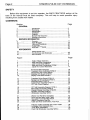
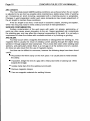
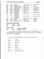
CONTENTS
Section Page
1
...............................
Introduction
.................................................................
3
2
...............................
Recelvmg
...................................................................
4
3
...............................
Specifications
.............................................................
4
4
...............................
Installation
..................................................................
5
5
...............................
Controls
......................................................................
10
6
...............................
Normal Weld Sequence
..............................................
14
7
...............................
Welding Performance
.................................................
15
8
...............................
Overview
....................................................................
17
10
.............................
Other Fault Conditions
................................................
26
11
.............................
Output Tests
...............................................................
27
12
.............................
Printed Circuit Boards
.................................................
28
13
.............................
Pads Lists
...................................................................
39
GENERAL
..
SERVICE INFORMATION
9
...............................
Fault Messages
..........................................................
19
APPENDICES
14
.............................
Weld Schedule List
.....................................................
49
15
.............................
Push-Pull Gun and Wirefeeder
...................................
54
16
.............................
Safe Practices
............................................................
61
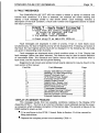
Figure Page
1
...............................
Supply Voltage Selection
............................................
5
2
...............................
Cable and
Hose
Connections
......................................
7
3
...............................
Cable Connections MMAW
.........................................
8
4
...............................
Cable and Hose Connections GTAW
..........................
9
5
...............................
Typical Arc Current Waveform
...................................
17
6
...............................
Functional Block Diagram
...........................................
18
7
...............................
Transistor Driver Assembly CP38-31
..........................
22
8
...............................
Descriptive and Current Signal
...................................
29
9
...............................
Welding CPU Board CP38-10
.....................................
30
10
.............................
Display CPU Board CP38-11
......................................
32
11
.............................
Transistor Driver Board CP38-12
................................
33
12
.............................
Background Driver Board CP38-13
.............................
34
13
.............................
Wire/Gas Board CP38-16
...........................................
35
14
.............................
Control Fuse Assembly CP38-17
................................
36
15
.............................
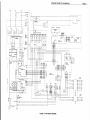
CDT 450 Circuit Diagram
............................................
37
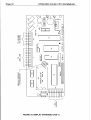
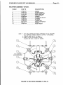
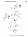
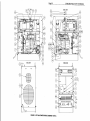
16 CDT 450 Assembly Diagram CP38-3 38
17
.............................
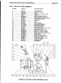
Main Switch Assembly CP38-21
.................................
40
18
.............................
Keypad-Display Assembly CP38-50
............................
42
.............................
..........................
19
.............................
Rectifier Assembly CP38-51
.......................................
43
20
.............................
Wirefeeder Assembly W35-0
......................................
44
21
.............................
W2-44 Two
Roll
Drive Assembly
...............................
45
24
.............................
AM223 Accessory Lead Kit
.........................................
48
26
.............................
Pull Gun Cable Assembly and Control Cable
..............
56
27
.............................
Hulftegger Gun Exploded View
...................................
57
29
.............................
Push Pull Wirefeeder Assembly W35-4
......................
60
22
.............................
Drive
Roll
and Wire Guide Table
................................
46
23
.............................
Gun Cable Assembly BE2-441 OA
...............................
47
25
.............................
Cable and
Hose
Connections, Push Pull
.....................
55
28
.............................
Torch Neck Assemblies
..............................................
59
~

SYNCHRO-PULSE
CDT
450
MANUAL
Paae
3
Y
The information contained in this manual is set out to enable you to properly
maintain your new equipment and ensure that you obtain maximum operating efficiency.
Please ensure that this information is kept in a safe place for ready reference when
required at any future time.
When requesting spare parts, please quote the model and serial no. of the
machine and part no. of the item required. All relevant part numbers are shown in lists
contained in this manual. Failure
to
supply this information may result in unnecessary
delays
in
supplying the correct parts.
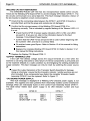
1.
INTRODUCTION.
The WIA SYNCHRO-PULSE CDT
450
is a multi-purpose arc welding power source
providing for the following arc welding processes:
GAS METAL ARC WELDING (GMAW) is an arc welding process where an electrode
wire is fed by motor driven rollers to a welding gun, and where D.C. welding current is
supplied
from
the welding power source. The welding arc is struck between the work
piece and the end of the wire, which melts into the weld pool. The welding arc is
established in a gas shield of carbon dioxide or argon-rich mixed gases.
PULSED GMAW is an extension of the GMAW process offering improved arc transfer
control. In Pulsed GMAW, the arc is supplied with D.C. welding current which is
modulated between two distinct values. The lower level is referred to as the
'Background Current', and the higher level as the 'Pulse Current'. Under the influence
of this pulsed current, the transfer of metal within the arc is ideally in the form
of
a
single droplet, approximately the diameter of the electrode wire, which is transferred
during the low energy period following each pulse.
PULSED GMAW is a full spray transfer process which is almost spatter free,
producing weld deposits of smooth appearance with excellent penetration and
sidewall fusion. The positive nature of arc transfer provides ease of puddle control in
'out of position' joints. The process expands the useful welding current range of a
given diameter electrode wire. Only argon or argon-rich gases are used for pulsed
GMAW.
MANUAL METAL ARC WELDING (MMAW) is a welding process where an arc is
struck between a flux-coated consumable electrode and the work piece. The arc and
the weld
pool
are both shielded by gases generated by the flux coating of the
electrode.
GAS TUNGSTEN ARC WELDING (GTAW) is a welding process where the arc is
struck between a non-consumable tungsten electrode and the work piece.
A
ceramic
nozzle surrounds the tungsten electrode and directs a flow of inert gas, usually Argon,
over the electrode and the weld zone. If filler metal is required, it is hand fed into the
welding arc. The DC current arc of the CDT
450
is suitable for welding most ferrous
and non-ferrous metals, but is not suitable for welding Aluminium for which an AC
machine is required.

Page
4
SYNCHRO-PULSE
CDT
450
MANUAL
2.
RECEIVING.
Check the equipment received against the shipping invoice
to
make sure the
shipment is complete and undamaged. If any damage has occurred in transit, please
immediately notify your supplier.
The SYNCHRO-PULSE CDT 450 package contains:
CP38-3 Power Source.
W35-0 Wirefeeder.
CP34-36 Remote Control pendant.
AM223-0/3 Inter-connecting Accessory lead kit, 3 metre.
w
BE2-441OWlA BERNARD Gun cable, 3 metre.
Regulator and Flowmeter. (Argon)
(This) Owners Manual.
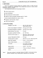
3.
SPECIFICATIONS.
PRIMARY VOLTAGE
.........................
380, 415, 440 Volts A.C.,
EFFECTIVE PRIMARY CURRENT
....
25
Amps (at 415 Volts)
MAXUMUM PRIMARY CURRENT
.....
36 Amps (at 415 Volts)
Three Phase,
50
Hz.
OPEN CIRCUIT VOLTAGE
................
70 Volts.
WELDING CURRENT RANGE
...........
35 -450Amps.
RATED OUTPUT (Note. 1)
.................
350 Amps,
100%
Duty cycle
CIRCUIT BREAKER RATING
.............
32 Amps
FITTED SUPPLY CABLE
...................
56/0.30 Four Core, Heavy Duty PVC
450 Amps, 60% Duty cycle
WIRE
SIZE
RANGE
............................
0.6mm
-
2.4mm diameter.
WIRE SPEED
RANGE
........................
A
to
q
6 Metredmin.
COOLING
..............................................
cooled, air drawn in
through rear fan grilles.
INSULATION
......................................
Class F, 115°C Rise.
DIMENSIQNS
.....................................
720mm
H,
430rnrn
W,
780mm
L.
MASS
.................................................
~63 Kg
Note.
l
Duty cycle
is
defined
in
Australian Standard AS1966.A as the ratio
of
arcing
time to
5
minutes in any
5
minute period, expressed as a percentage.

SYNCHRO-PULSE
CDT
450
MANUAL
Page
5
4.
INSTALLATION.
A@€.
Al1,electiical work shall only be undertaken by a qualified electrician. Before
removieg
any
smachine,8covers,'
ENSURE
that the unit
,is
disconnected from the electrical
supbly.;
fl~n
the8~clnitl"is~energised
LETHAL
V,OLTAGES
are present on these/ectricall
cbrnponeots~~~encIoseti.
8'
-
-
CONNECTION
TO
ELECTRICAL SUPPLY
The SYNCHRO-PULSE CDT 450 is supplied with a
3
metre, 4 core
56/0.30
Heavy
Duty PVC Supply Flexible cable. The supply cable must be correctly connected to
a
suitable
3
Phase plug top or fixed connection point.
The minimum capacity of the mains wiring and power outlet supplying a welder
is
selected according to the
effective primary current
of
the machine. The effective primary
current for
a
SYNCHRO-PULSE CDT 450 is
25
Amps. The minimum recommended
circuit breaker rating for a SYNCHRO-PULSE CDT
450
is
32
Amps.
The current rating of the mains cable depends on cable size and method of
installation. Refer to AS/NZS
3008.1,
Table
9.
If
it becomes necessary to replace the
mains flexible supply cable,
use
only cable with correct current rating.
Access to the machine supply terminals is gained by removing the power-source
side panel adjacent to the supply cable entry. Pass the replacement cable through the
bush fitted to the machine back panel. The Earth wire (green
/
yellow) must be securely
attached to the marked Earth stud. The three supply phases are terminated at the Main
Contactor. Remove the contactor dust cover to gain access to the connection points.
Ensure that the internal Brown and Blue loom wires remain connected to the 'live' side of
the contactor. Tighten the cable clamp leaving sufficient slack in the cable such that the
terminated wires are not in tension.
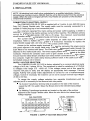
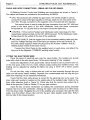
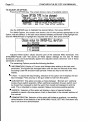
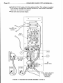
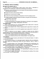
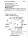
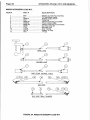
SUPPLY VOLTAGE SELECTION
The SYNCHRO-PULSE CDT 450 is factory adjusted for a nominal electrical supply
voltage of 41
5
volts,
3
phase,
50
Hz. The equipment is rated for variations of
k
IO%,
that
is voltages in the range
375
-
455V AC. If the voltage moves out of this range the
machine will cease to weld, and will display an appropriate fault message. The local
Supply Authority will usually make adjustments to correct for out of tolerance supply
voltage, however if necessary the machine can be set to accept nominal input voltages
of
380
or 440 Vac.
To change the supply voltage selection
two
separate transformers must be
adjusted, and it is necessary to first remove both side panels.
I
The Control Transformer terminal strip
is
located on the side
of
the machine
nearest the
Off
/
On switch. Move the Brown wire to the intended input voltage
tapping.
adjacent to the Supply Flexible cable. Move the wire link to the intended input
The Welding Transformer terminals are located on the side
of
the machine
voltage tappings.
MAIN
TRANSFORMER
1380
c
L2
I
'115
L':
440
l
I
1
LINK
A-
BLt
CONTROL TRANSFORMER
J
FIGURE
l.
SUPPLY VOLTAGE SELECTION.

Page
6
SYNCHRO-PULSE CDT
450
MANUAL
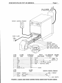
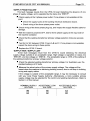
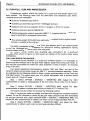
CABLE
AND
HOSE CONNECTIONS
-
@MAW
AND PULSED
GMAW.
All Welding Current, Control and Shielding gas connections are shown in Figure
2.
The cables and hoses are contained in the accessory kit AM223.
9
GAS. The accessory kit contains
two
gas hoses. The shorter length is used to
connect the output of the gas regulator to the gas nipple on the rear panel of the
CDT
450.
The gas connector for the regulator end is included with the regulator.
The second hose is used to make the gas connection from the CDT
450
front
pane! to the back panel of the W35 wirefeeder. Note that these connectors
incorporate an
'OB
ring seal and do not require excessive tightening.
CONTROL. Fit the Control Pendant and Wirefeeder cable male plugs into their
respectively marked sockets on the CDT
450
front panel. Fit the Wirefeeder cable
female plug into the socket at the rear of the wirefeeder.
WELDING CABLES. Bolt the lugged end
of
the wirefeeder welding cable plus the
grey Arc Voltage Sensing wire to the brass gun adaptor of the
two
roll drive. Fit
the cable clamp supplied. Attach the plug end to the Positive 'GMAW
/
PULSE'
welding output socket of the power source.
plug end to the Negative 'COMMON' welding output socket.
Connect the Work Clamp to the welding bench or work piece, and attach the
FITTING THE ELECTRODE WIRE
Place the spool
of
electrode wire onto the spool holder. The location pin should
mate with a hole in the wire
spool
body. Fit the spool retaining
'R'
clip supplied.
Check the adjustment of the spool brake, which should be set to prevent over run
of the wire
spool
at the end of
a
weld, without unduly loading the wirefeed motor. The
braking
can
be adjusted by rotating the Nyloc nut using
a
15/16"
AF or
24mm
socket
wrench.
Do
not use dirty, rusty or kinked wire as
it
will not feed smoothly through the gun
cable and will cause erratic welding. Deposits from contaminated wire will clog the gun
cable liner requiring it to be replaced prematurely.
Check that the drive roller groove is correct for the electrode wire to be used. The
drive roller part number
is
marked on the visible side of the installed roller. Refer to the
drive roller selection chart in Figure
22.
Check also that the correct size contact tip is
fitted at the gun end. Refer to Section
13
for gun part numbers.
Open the two roll drive mechanism by rotating the compression spring assembly
towards the front of the wirefeeder, allowing the upper roller housing to be lifted away
from the driven roller. Straighten the end of the welding wire and pass it through the inlet
guide, over the bottom driven roller and into the gun cable adaptor guide tube. Return
the top roller to the closed position.

SYNCHRO-PULSE
CDT
450
MANUAL Page
7
GAS CYLINDER
&
REGULATOR
REMOTE CONTROL PENDANT
'WORK' CLAMP
CONTROL CABLE
W/F WELDING CABLE
GUN CABLE ADAPTOR
GREY VOLTAGE SENSE
WIRE
u%!i
!LmE
8
PIN PLUG
PLUG
€!Lx
&
SOCKET WIRE FEEDER
W35-0
EL
GUN PLUG WELDING
&
SOCKET
-
GUN
2
+
TWO
"3?
RED
"J
((
S$~&~
t
3
t
THREE
'47
BLACK
4
+
FOUR
-i$r-
BLACK
5
t
FIVE
\$
GREY
-
(VOLTAGE SENSE)
6
+
SIX//6
7
t
SEVEN
/,7
8
t
GREEN/YELLOW
d8
SPARE
I
t
ONE
-+
BLACK-
-
(W/F MOTOR)
3
PIN
3
CORE
PLUG
m
REMOTE CONTROL PENDANT
2
t
BROWN
-
CURRENT
1
t
BLUE
-
ARC LENGTH
3
t
GREEN
-
COMMON
1
-'CURRENT'
'ARC LENGTH
FIGURE
2.
CABLE
AND HOSE CONNECTIONS, GMAW AND PULSED GMAW.

e
Page
8
SYNCHRO-PULSE
CDT
450
MANUAL
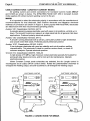
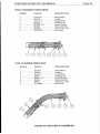
CABLE CONNECTIONS
-
CONSTANT CURRENT MODES.
All welding current and control connections for Constant Current modes MMAW
and GTAW are shown in below. The SYNCHRO-PULSE CDT
450
in Constant Current
mode supplies DC (direct current) welding current to the arc.
MMAW.
It is important to select the electrode polarity in accordance with the manufacturers'
recommendations for that electrode. Both Positive electrode and Negative electrode
methods of connection are shown in Figure 3. Some popular WIA AUSTARC electrodes
are listed below with their recommended operating polarity.
Austarc 12P, Classification AS1
553,
E41
12.
A popular general purpose electrode used with ease in all positions, vertical up
or
down. The smooth forceful arc makes it an ideal electrode for all general mild steel
applications. Preferred polarity electrode positive.
A smooth running electrode with
a
soft
arc, particularly suited to light sheetmetal
and smooth mitre fillet welds. Preferred polarity electrode positive.
A low hydrogen electrode with good arc stability and out-of-position welding
characteristics. This electrode
is
ideal for medium carbon steels,
or
steels of
unknown analysis. Operate electrode positive.
A
high tensile
(770
MPa), high chromium nickel electrode specially formulated
for
joining all alloy steels and irons, and for tool and die maintenance. Operate
electrode positive.
Austarc 13S, Classification AS1 553,
E41
13.
Austarc 16TC, Classification AS1
553,
E481
6.
Unicord 31 2, Classification AS2576, 1330-A3
~
When Constant Current mode schedules are selected, the Arc Length control is
reconfigured as an output Off-On control switch. Rotate the potentiometer clockwise to
energise the welding output, and anti-clockwise to de-energise the welding output.
ELECTRODE POSITIVE
OUTPUT
ON
ELECTRODE NEGATIVE
1
l
no
~UUO
no
1:
0
unoo
OUTPUT
ON
\
Y
n
I
FIGURE
3.
CONNECTIONS FOR MMAW.

~
SYNCHRO-PULSE CDT
450
MANUAL Paae
9
~~
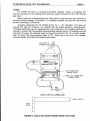
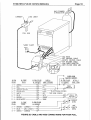
GTAW.
For
GTAW
the torch is connected electrode negative. Figure
4
illustrates the
correct connection of the welding torch and gas supply utilising the
CDT
450
internal
gas valve.
Before initial use
of
the welding torch, allow gas to purge the torch and hoses
for
5
minutes at approximately
IO
litreslmin. For welding purposes, the gas flow rate should
be set
in
the range
2-5
litredmin.
Tungsten electrodes
for
DC
GTAW should be
l
-
2%
Thoriated. This type will
provide the best arc initiation, arc stability and tip shape retention characteristics.
Thoriated electrodes can be recognised by a red coded end. The tungsten electrode is
ground to a point, with the grinding marks pointing towards the tip.
For
welding currents
less than
20
amps, the included angle of the point should be
30°,
for currents greater
than
20
amps, the recommended angle
is
60".
When set in the torch, the tungsten
should protrude 12mm from the ceramic gas nozzle.
l7
l
GAS
CONNECTIQN
(WHERE
USED)
-0RCH
SW.
CONNECTION
(WHERE
USED)
TORCH SWITCH CONNECTION
1)
2)
TORCH SWITCH
3)
8
PIN
4
)
PLUG
5
)
6)
7)
8)
j
FIGURE
4.
CABLE AND HOSE CONNECTIONS
FOR
GTAW.

Paae
IO
SYNCHRO-PULSE
CDT
450
MANUAL
W
5.
CONTROLS.
The SYNCHRO-PULSE CDT
450
power source is equipped with an operator
keypad panel and a graphical display screen. All control facilities of the machine are
accessed by use of the keypad. The individual key names and functions are:
SCHEDULE used to select a Welding Schedule;
OPTION used to modify Weld and general purpose Options;
ARROW KEYS used to position the highlight bar over a menu item.
ENTER used to select the menu item;
HELP used to view 'Help' information for the current menu;
INCH used to Inch the electrode wire forward;
PURGE used to Purge the shielding gas hoses.
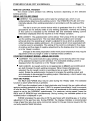
The display screen provides information such
as:
The selected Weld Schedule
or
Process;
The selected wirefeed rate;
The estimated welding current;
Actual weld current and voltage during welding;
Average weld current and voltage during the last weld;
Advice of any detected fault condition.
When the machine
is
first energised, the screen briefly displays the WIA
logo
during which time the microprocessor circuits are performing self-test routines. When
these checks have been completed, and provided that no fault conditions exist, the
screen will display information simitar
to
that shown below. For assistance with fault
messages, refer to Section
9
of
this manual.
#l97
85.9
ER316L
8.8
STAINLESS
316L
GAS:
ARGON
+5#t
HE
+2
C&
'IRE
5.2
mlmin
CURRENT:
APPROX.
FEED
:
75
ips
I
I
The display indicates the presently selected Weld Schedule with its internal library
number, the recommended
gas
composition, the set wirefeed rate, the estimated
welding current and an Arc Length setting indicator. This
is
referred to
as
the 'Ready'
state, as the machine is ready to weld with the settings displayed.

SYNCHRO-PULSE CDT 450 MANUAL
Paae
l l
~~
v
TO
SELECT
A
WELD
SCHEDULE.
From the SCHEDULE menu, GMAW, Pulsed GMAW, MMAW and GTAW
schedules can be selected. The Pulsed GMAW Weld Schedules available have been
established for specific combinations of electrode wire type, wire diameter, and shielding
gas mixtures. More than
100
combinations are available in the CDT
450
library. It is
important that the correct Weld Schedule be selected for the consumables (wire and
gas) in use.
Press the SCHEDULE key. The screen will display a list of weld schedule groups
beginning with electrode types for Pulsed GMAW. Use the ARROW keys
to
position the
highlight bar over the required group, then press ENTER. When 'on-line' programming,
Weld Schedules sent to the machine from a separate programming device are
accessible through the DOWNLOAD group.
-
1
Choose
ELECTRODE
TYPE
required:
EPROM
:
COPPER
&
ALLOYS
#33
125
FLUX
CORED
WIRES
#3##07
l
I
Use the ARROW keys to highlight the required schedule, then press
ENTER.
1.2rnrn
STRINLESS
318 A5.9
ER318
8.9mrn
STAINLESS
312
A5.9
ER312
0.9mrn
STAINLESS 316LSi
BHP
3CR12
plutle
I
I
Section
14
of this manual lists all of the Pulsed GMAW weld schedules currently
available in the
CDT
library, together with their individual schedule numbers.
In
addition
to the method described above, weld schedules may also be selected directly by
number. This feature is available
as
the last item in the SCHEDULE menu. When this
mode is in use, the screen will initially display the number
of
the currently selected weld
schedule. Using the ARROW and ENTER keys, index each digit to show the number
of
the new schedule required, then press ENTER.
OPTIONS
The
OPTION
menu provides
two
groups of Options
as
shown below. The first
group of Weld Options are specific to the selected Weld Schedule, providing adjustment
of:
Pre-gas time;
w
Creep speed;
Crater-fill time;
Burn-back time;
Post-gas time.
The remaining options are not specific to the selected Weld Schedule, and provide
the following features:
Recall of the last weld Current and Voltage data;
Selection of standard
or
latching gun-switch modes;
Servicing tests;
Demonstration display.
l
Recall of the last Fault message;

Page
12
SYNCHRO-PULSE
CDT
450
MANUAL
TO
ADJUST AN OPTION.
Press the OPTION key. The screen shows a menu of available options.
Chum
OPTION
TYPE
to.
be
chunged:
POST-GAS
-
gus
flow
time
ufter welding
I
I
Use the ARROW keys to highlight the desired Option, then press ENTER.
For
Weld Options, the screen now shows a list of time periods appropriate to the
Option, with the default,
or
the last value selected already positioned in the highlight bar.
Use the ARROW keys
to
highlight the required new value, then press ENTER.
"
[how
vulue
far
CRATER-FILL
durutiw:
I
nil
seconds
1.2
seconds
1.5
slecclnds
I
I
Adjusted Weld Option values become part of the selected Weld Schedule. The
SYNCHRO-PULSE CDT
450
stores all Weld Option settings for the last
16
Weld
Schedules used, and automatically applies the adjusted values whenever one of these
schedules is selected.
The remaining Options provide the following facilities:
INFORMATION. Display of Current and Voltage data relating to the last weld
performed. The figures are averages taken over the last one second of the
weld,
excluding Crater-fill and Burn-back periods. Press any key to exit from this
display.
FAULT. To assist with fault finding, selection of this option will re-display the last
fault message. Press any key
or
the gun switch to exit from this option.
GUN SWITCH. This option provides a choice between 'Normal' and 'Latching'
modes of gun-switch operation. When Latching
is
selected, the gun switch must
be closed then released to start the weld, then closed and released
to
end the
weld. This is intended to reduce operator fatigue during long welding periods.
SERVICE. Selection of this option will display
a
menu of special facilities
available to assist a Service person. Each is described in the relevant sections of
this manual.
DEMONSTRATION. Selection of this option will initiate a graphical, non welding
demonstration of the features of the SYNCHRO-PULSE
CDT
450.
Hold
down any
key to exit from the demonstration.

SYNCHRO-PULSE
CDT
450
MANUAL
Page
13
REMOTE CONTROL PENDANT
welding process.
GMAW AND PULSED GMAW
The remote control pendant has differing functions depending on the selected
CURRENT. This potentiometer control sets the wirefeed rate, which in turn
fundamentally determines the welding current. The SYNCHRO-PULSE CDT
450
internally adjusts other welding parameters in accordance with the setting of this
control.
The dial is a ten-turn vernier device which is graduated from
0
to
10.00.
The
graduations do not directly relate to any welding parameter, however the setting
of this control is indicated by the wirefeed rate and estimated welding current
information displayed when the machine is
in
the 'Ready' condition.
ARC LENGTH. This potentiometer control allows 'fine tuning' of the arc length to
suit the welding requirement. The most ideal welding conditions are normally
achieved when the operating arc length is adjusted to be as short as practicable,
while maintaining a stable welding arc. An occasional short circuit associated with
a crackle sound
is
acceptable. The setting of this control is indicated in five steps
of positive and five steps of negative adjustment by the display when the machine
is in the 'Ready' condition.
Changes to the weld preparation and/or work piece temperature may require
adjustment of the arc length
in
order to maintain these conditions.
CONSTANT CURRENT MODES
-
MMAW AND GTAW
CURRENT. This control sets the output welding current directly within the range
of the selected Constant Current schedule. The estimated welding current is
displayed when the machine
is
in the 'Ready' condition.
ARC LENGTH. Arc length control is not appropriate to MMAW and GTAW which
are both Constant Current welding processes. When these schedules are
selected, the Arc Length control is reconfigured as an output
Off-On
control
switch. Rotate the potentiometer clockwise to energise the welding output, and
anti-clockwise to de-energise the welding output. Alternatively,
a
torch switch may
be connected as shown in Figure
4.
INCH AND PURGE.
The INCH and PURGE keys may be used during the 'Ready' state. The selected
function is active while the key is pressed.
INCH runs the wirefeed motor to feed electrode wire through the gun cable without
applying welding potential to the wire. If INCH
is
pressed momentarily, small increments
of wire are fed. If the key is held down, the motor will accelerate to the welding wirefeed
speed as set by the CURRENT potentiometer.
For
maximum inching speed, press the
INCH and UP ARROW keys simultaneously. During inching, the intended speed of the
wirefeed motor is displayed
in
rpm.
PURGE energises the gas valve to fill the gas hoses with shielding gas,
or
to allow
adjustment of the gas flow rate. During PURGE, the display indicates a recommended
range of gas flow rate, plus some commercial names for the gas mixture required for the
currently selected Weld Schedule.

Page
14
SYNCHRO-PULSE
CDT
450
MANUAL
HELP KEY.
At any stage of operation of the CDT
450
(except during welding), the HELP key
may be pressed to display additional information relating to the present operating mode
of the machine. To exit from each message, press the HELP button a second time.
STANDBY MODE.
The SYNCHRO-PULSE CDT
450
incorporates a power-saving standby mode. If
the machine is left idle for more than
25
minutes, the welding transformer and cooling
fans are de-energised and a 'Standby' message is displayed. Use of the keypad
or
gun
switch will return the machine to normal operation.
6.
NORMAL
WELD SEQUENCE.
GMAW AND PULSED GMAW
WELD START.
The gas valve opens allowing shielding gas to flow for the selected Pre-gas time;
Welding voltage is applied between the electrode wire and the work piece;
Wirefeed commences at creep speed;
The wire contacts the work piece, and the arc
is
established. Wirefeed steps to
run speed as determined by the setting of the remote Current control.
During welding, the screen displays information similar to that shown below. The
actual arc voltage and current
is
displayed both as a digital number, and in bar-graph
form.
L
8.9
AUSTMIG
316LSi
135.9
ER316LSi
24
V
0
lI1S1111111
10 20
30
40
50
75
fi
B188
288
3aa
488
588
I
nl111111s1
l
I
WELD END.
If a non-zero value of Crater fill has been selected, the wirefeed motor slows over
the time period selected;
The wire drive motor is dynamically braked to a stop;
Welding voltage is held 'On' for the selected 'Burnback' time. Burnback ensures
that the electrode wire does not freeze in the solidifying weld pool.
The gas valve is held 'On' for the selected Post-gas time. Post-gas allows the
After welding, the screen displays information relating to the last weld. The
molten weld pool to solidify before exposure to atmospheric gases.
Current and Voltage figures shown are averages taken over the last one second
of the last weld excluding crater-fill and burnback periods. The information
is
displayed for
IO
seconds,
or
until a key is pressed. The same information can be
recalled
by
selecting OPTION
>
INFORMATION.

SYNCHRO-PULSE CDT
450
MANUAL
Page
l5
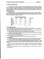
7.
WELDiNG
PERFORMANCE.
GMAW AND PULSED GMAW.
GMAW equipment can only provide optimum results if all external components are
correctly installed, adjusted, maintained, and the correct consumables are being used.
In a situation of unsatisfactory welding results, the welding power source is often the first
item suspected, however the fau!t frequently lies in these more routine areas.
SHIELDING GAS
In GMAW, and especially Pulsed GMAW, the shielding gas composition plays a
most important part in establishing correct arc behaviour.
Each SYNCHRO-PULSE CDT 450 pulsed weld schedule has been established for
use
with a specific gas mixture. It is important that the gas mixtures recommended be
adhered to. The gases specified are all Argon rich, and in some cases are 100% Argon.
Carbon Dioxide gas alone is not suitable for pulse welding, but it is a component in
mixtures used
for
several applications, and can be used for non-pulsed
G.M.A.W.
One function of the shielding gas is to protect the molten weld pool from the effects
of oxygen in the atmosphere. Without this protection the weld deposit becomes
'honeycombed'
in
appearance, an effect which is described as weld porosity.
In draft-free conditions the gas flow rate required to give adequate protection is
typically 10 litres/min.
In
situations where drafts cannot be avoided, it may be necessary
to increase this rate and/or to provide screening of the work area. Holding down the
PURGE key will display a recommended minimum gas flow rate for the selected
schedule.
If weld porosity occurs:
Remove spatter build-up from inside the gun nozzle. Check for fraying of the
internal nozzle insulator, and replace the nozzle if necessary.
w
Check that the gas hoses have not become cracked
or
frayed, and that the
rubber seals in each gas connection point are not broken
or
perished.
Check the gas flow rate at the nozzle, and compare this reading with the flow rate
at the regulator.
A
discrepancy may indicate
a
previously undetected gas leak.
WIREFEED
In any GMAW process, the electrode wirefeed must be smooth and constant
in
order to obtain the most satisfactory welding results.
It
is important to observe the
following points:
Minimise the build up of dirt, dust and swarf in the gun cable liner by the use of
clean electrode wire. Ensure that the compression force of the drive rollers
is
not
excessive, and that the rollers have been correctly selected for the welding
electrode in use. For drive
roll
data, refer to Figure
22
of this manual.
The gun cable liner must be correctly fitted
so
that the free end seats firmly into
the back of the welding gun head. In this way the electrode wire is supported and
guided directly into the welding tip. Refer to Section 13 for liner fitting instructions.
Replace the welding tip
as
it becomes worn.
Check that the electrode wire spool holder rotates smoothly and that the braking
action is not excessive.

l
Page
l6
SYNCHRO-PULSE
CDT
450
MANUAL
ARC LENGTH.
The most ideal pulsed GMAW welding conditions are achieved when the arc length
is adjusted to be as short as possible while maintaining a stable spray mode of welding
arc. Occasional arc short circuiting, associated with a crackling sound, is acceptable.
Changes
in
weld preparation and/or work piece temperature may require adjustment
of
the arc length to maintain these conditions.
If the arc length is too short, it will result in excessive crackle, shorting and spatter,
while if too long may result in weld undercut and lack of weld penetration.
SURFACE CONTAMINATION.
Surface contamination of the work piece with water,
oil,
grease, galvanising,
or
paint can often cause severe disruption to the arc. Gases generated can contaminate
the shielding gas, and may affect the chemical composition of the weld. It is normally a
requirement to clean the surface with a suitable solvent
or
by linishing
or
grinding.
ARC BLOW.
Arc blow occurs when a magnetic field distorts
or
extinguishes the welding arc. The
magnetic field is usually the result
of
welding current passing through the object being
welded
or
through adjacent steel clamp bars. This is most often seen when welding steel
sections, and particularly where there is a root gap or at the extreme end of a section.
Arc blow
can
also result from the use of magnetic clamps.
Arc blow can be difficult to overcome, however the following steps have been found
useful:
Re-position the Work clamp on the work piece. It
is
usually best to weld towards
the clamp;
If
possible, bridge the end
of
a gap with a heavy tack weld
or
backing bar. Weld
towards the bridge;
m
Isolate clamp bars from the welding current path;
Remove magnetic clamps;
Use non-magnetic materials for welding fixtures.

SYNCHRO-PULSE
CDT
450
MANUAL
Paae
17
~
-~~
-
.
~
~~-
-
SERVICE INFORMATION.
CONTROL CIRCUIT MAINS FUSES
The supply circuit to the Control Transformer is protected by two
H.R.C.
fuse links.
These fuses are located inside the power source and are only accessible by removing
the right hand side panel.
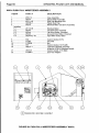
8.
OVERVIEW
OF
PULSED
GMAW.
When set for pulsed
GMAW,
the SYNCHRO-PULSE CDT
450
supplies to the
l.
Current pulses
of
controlled amplitude, time duration and frequency.
2. Controlled amplitude background current.
Typical value ranges for these parameters are:
welding arc a
DC
current comprising two distinct elements. These are:
Pulse current peak:
200
-
600
amps;
w
Pulse width:
2
-
5
mS;
Pulse frequency:
30
-
400
Hz;
Background current: 12
-
75
amps average.
/-
'WINDOW' UPPER
11
I
'WINDOW' LOWER
I,
/
CURRENT PULSE
BACKGROUND CURRENT
/-
'WINDOW' UPPER
1
'WINDOW' LOWER
/
CURRENT PULSE
I
\
BACKGROUND CURRENT
Ih
a
J
4-w
11
I
I,
I
Y
FIGURE
5.
TYPICAL ARC CURRENT WAVEFORM.

~
Paae
18
SYNCHRO-PULSE
CDT
450
MANUAL
Y
The individual pulse and background parameters, plus pulse frequency, wirefeed,
arc voltage and other data have been predetermined to suit the welding electrode and
shielding gas combination. These parameters together are referred to as a 'Weld
Schedule'. The SYNCHRO-PULSE CDT
450
has an internal library of over
100
weld
schedules, allowing Pulsed
GMAW
using a wide range of electrode wire types, wire
diameters and shielding gas combinations.
The pulse and background currents are both derived
by
'switch-mode' control.
In
this technique, the welding current
is
repeatedly switched On and
Off
in such a way that
the current is held within
a
specified 'window' range.
The SYNCHRO-PULSE CDT
450
has separate switches for pulse and background
current. The pulse current switch is a bank of three high current bipolar transistors
mounted on a fan cooled, monolithic heatsink. The background switch is a bank
of
three
Mosfet transistors. The basic D.C. welding current is the rectified and filtered output of
a
three phase welding transformer.
Central to the CDT
450
is a microprocessor based control circuit CP38-10. This
circuit takes input from the press button keypad and remote control pendant, plus
current and voltage feedback
from
the arc, and in turn controls the drivers for each of
the current switches. The circuit also manages the flow of shielding gas, wire feed and
feed rate and sends data to the graphical display.
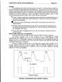
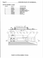
The block diagram illustrates the connections between the control blocks of the
SYNCHRO-PULSE CDT
450.
DISPLAY
I
Y
REMOTE
CONTROL
I
DlSpBLoAAvR~PU
b
I
PRESS-BUTTON
CP38-11 KEYPAD
M
I
I
t
I
I
ARC
CURRENT
FEEDBACK
t
*
BACKGROUND
*
DRIVER BOARD
b
CP38-13
WELDING CPU BOARD
CP38- 10
ARC
VOLTAGE
k
FEEDBACK
TRANSISTOR
+
DRIVER BOARD
t
CP38-12
I
GUN SWITCH
WIREISAS
CONTROL BOARD
CP38-16
WIREFEED
MOTOR
FIGURE
6.
FUNCTIONAL
BLOCK
DIAGRAM.

i
i
SYNCHRO-PULSE
CDT
450
MANUAL
Paae
19
Y
9.
FAULT
MESSAGES
The SYNCHRO-PULSE CDT
450
has means to detect a variety of external and
internal fault conditions. If a fault is detected, the machine will cease welding and
display a fault message similar to that shown below. Each message includes a
description of the fault condition, a fault code number and suggested actions to assist
with fault correction.
*
Check
plug
P3
Q~I
Weld
CPU CP38-l#.
I
FAULT
-
R&e
Pendud
DiSCDnnECtEd
I
#
Check that
the
control pendant
plug
is
correctly
inserted) and
that
the
cuble
is
not
damaged.
$
Tt-y
another control pendant.
l
I
Fault messages are displayed in order
of
priority. If
two
or
more faults occur
simultaneously, the fault of highest priority will be displayed first. Following correction of
that fault, the next highest priority fault will be displayed. In the following list, the faults
are given
in
descending order of priority.
Fault messages are displayed when
a
fault condition exists,
or
if
the 'Display last
fault message' Option has been selected. This feature may be used to assist detection
of
intermittent faults. The Schedule and Option menus may still be accessed when a
fault exists, but the machine will not permit welding.
Diagrams for all circuits and printed circuit boards referred to may be found in the
next section of this manual.
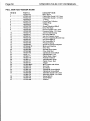
Fault
No.
Fault Message Page
1
..............................
Display CPU Memory Problem'
..................
19
3
..............................
Output Terminals Live'
...............................
20
6
..............................
Supply Phase Failure'
................................
23
7/8
..........................
'Supply High
/
Supply Low'
.........................
23
2
..............................
Welding CPU
Not
Responding'
..................
20
4
.............................
.CPU Board Power Supply'
.........................
20
5
..............................
Transistor Driver Power'
.............................
21
9
............................
.'Background Driver Power'
..........................
24
10
...........................
'Overcurrent Detected'
................................
24
11
............................
Thermostat Overheated'
.............................
24
12
........................
...'
Arc Voltage Sensing Problem'..
..................
25
13
...........................
'Wirefeed Control Problem'
.........................
25
14..
..........................
Remote Pendant Disconnected'
.................
26
15
......................
.....'
External Detection Input'
............................
26
'DISPLAY CPU MEMORY PROBLEM'
This message results from
two
possible conditions relating to the Display CPU
Assembly CP38-11. The first is an incorrect checksum result obtained during the power-
up sequence which indicates corruption
of
the Eprom data. The second is failure of the
RAM read/write power-up test.
Fit a new Eprom to the CP38-1
l
board. Refer to Section 12 of this manual for
fitting instructions.
Replace the complete printed circuit assembly CP38-11.
I

Paae
20
SYNCHRO-PULSE
CDT
450
MANUAL
Y
'WELDING
CPU
NOT RESPONDING'
The SYNCHRO-PULSE CDT
450
has two microprocessor based control circuits.
These are the Welding CPU Board CP38-IO, and the Display CPU Board CP38-11. The
two
circuits communicate via a serial data link. This fault message indicates a failure of
the
two
boards to establish correct communications.
w
Check that the connecting cable between the CP38-11 and CP38-10 boards is
Confirm that the microprocessor
of
the Welding CPU board CP38-10 is
correctly fitted, and that the plugs and sockets are not damaged.
functioning correctly. This is indicated by regular flashing of the 'Beacon' LED
4.
If
it is not:
Check that the CP38-10 power supply indicators LEDI, LED2, and LED3
are each lit. If any are not, refer to the information below for the fault
message 'Circuit Board Power Supply'.
the numbers '380', and that it is correctly fitted.
instructions.
this manual for fitting instructions.
w
Confirm that the CP38-10 has an Eprom with
a
code number beginning with
Fit another known good Eprom. Refer to Section 12
of
this manual for fitting
Replace the complete Welding CPU board CP38-10. Refer to Section
12
of
Replace the Display CPU Board CP38-11.
'OUTPUT TERMINALS
LIVE'
If the CDT
450
detects voltage across the output terminals at a time when the
machine is not being instructed to weld, failure of internal components is presumed and
so
the machine defaults to a safe condition by de-energising the welding transformer
supply contactor. This fault message can only be reset by switching the power source
Off.
Inspect the output transistors of the Transistor Switch Assembly for damage.
Using an ohmmeter, ensure that the transistor collector
/
emitter junctions are not
short circuited. If any components have failed, the complete Transistor Switch
Assembly CP38-21 must be replaced. Refer to Figure 17.
'CPU
BOARD POWER SUPPLY.'
This fault message is displayed if a Welding CPU onboard power supply is
not
available. The supplies are each powered
from
electrically isolated control transformer
windings which are individually fused on the Control Fuse Assembly Board CP38-17.
The table below relates each power supply to its LED indicator number and fuse
number.
CP38-10 CP38-17
CPU
+5v
LED 3 Fuse F7
CPU -15V LED 2
Fuse F5
CPU +15V LED
l
Fuse
F6
SHUNT AMP +/-l
5V
No LED Fuse
F4
l
l
Page is loading ...
Page is loading ...
Page is loading ...
Page is loading ...
Page is loading ...
Page is loading ...
Page is loading ...
Page is loading ...
Page is loading ...
Page is loading ...
Page is loading ...
Page is loading ...
Page is loading ...
Page is loading ...
Page is loading ...
Page is loading ...
Page is loading ...
Page is loading ...
Page is loading ...
Page is loading ...
Page is loading ...
Page is loading ...
Page is loading ...
Page is loading ...
Page is loading ...
Page is loading ...
Page is loading ...
Page is loading ...
Page is loading ...
Page is loading ...
Page is loading ...
Page is loading ...
Page is loading ...
Page is loading ...
Page is loading ...
Page is loading ...
Page is loading ...
Page is loading ...
Page is loading ...
Page is loading ...
Page is loading ...
Page is loading ...
-
 1
1
-
 2
2
-
 3
3
-
 4
4
-
 5
5
-
 6
6
-
 7
7
-
 8
8
-
 9
9
-
 10
10
-
 11
11
-
 12
12
-
 13
13
-
 14
14
-
 15
15
-
 16
16
-
 17
17
-
 18
18
-
 19
19
-
 20
20
-
 21
21
-
 22
22
-
 23
23
-
 24
24
-
 25
25
-
 26
26
-
 27
27
-
 28
28
-
 29
29
-
 30
30
-
 31
31
-
 32
32
-
 33
33
-
 34
34
-
 35
35
-
 36
36
-
 37
37
-
 38
38
-
 39
39
-
 40
40
-
 41
41
-
 42
42
-
 43
43
-
 44
44
-
 45
45
-
 46
46
-
 47
47
-
 48
48
-
 49
49
-
 50
50
-
 51
51
-
 52
52
-
 53
53
-
 54
54
-
 55
55
-
 56
56
-
 57
57
-
 58
58
-
 59
59
-
 60
60
-
 61
61
-
 62
62


WELDING INDUSTRIES Synchro Pulse CDT450 Owner's manual
- Category
- Welding System
- Type
- Owner's manual
- This manual is also suitable for
Ask a question and I''ll find the answer in the document
Finding information in a document is now easier with AI
Other documents
-
Saxby Lighting 46896 Operating instructions
-
WIA Weldmatic Synchro Pulse Owner's manual
-
ESAB Linde 65 Nozzle Compound Electric Welding Troubleshooting instruction
-
 Saxby Lighting 43816 User manual
-
Multibrackets 7 350 073 732 067 User manual
-
-
-
-
-
